 Dynamic Sketch Panel
The menu item to show and hide the Dynamic Sketch panel can be found in the main menu under Window > Astute Graphics > Dynamic Sketch.
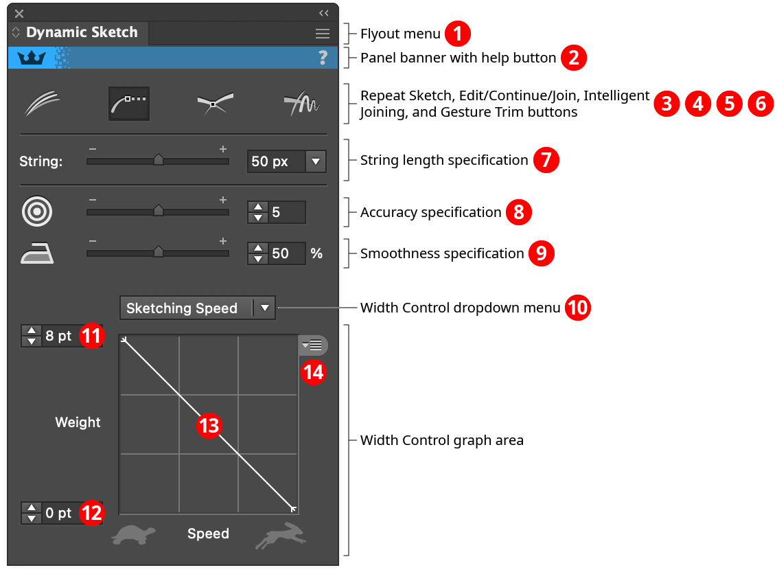
Dynamic Sketch Panel
1. Flyout menu
See Dynamic Sketch Panel: Flyout Menu.
2. Panel banner
The Dynamic Sketch panel banner has a help button on the right which opens the help documentation in the Astute Manager. If this does not automatically appear, please ensure your Astute Manager is running first. Along with the rest of the panel, the panel banner can be clicked to activate the Dynamic Sketch tool. This is a quick method of locating the tool within the default Advanced toolbar or a custom toolbar.
3. Repeat Sketch Button
Toggles Repeat Sketch mode for the Dynamic Sketch tool. When Repeat Sketch is enabled, the tool can be dragged multiple times and the final path will be an average of all the individual sketch paths (both positions as well as widths), thereby smoothing it out:
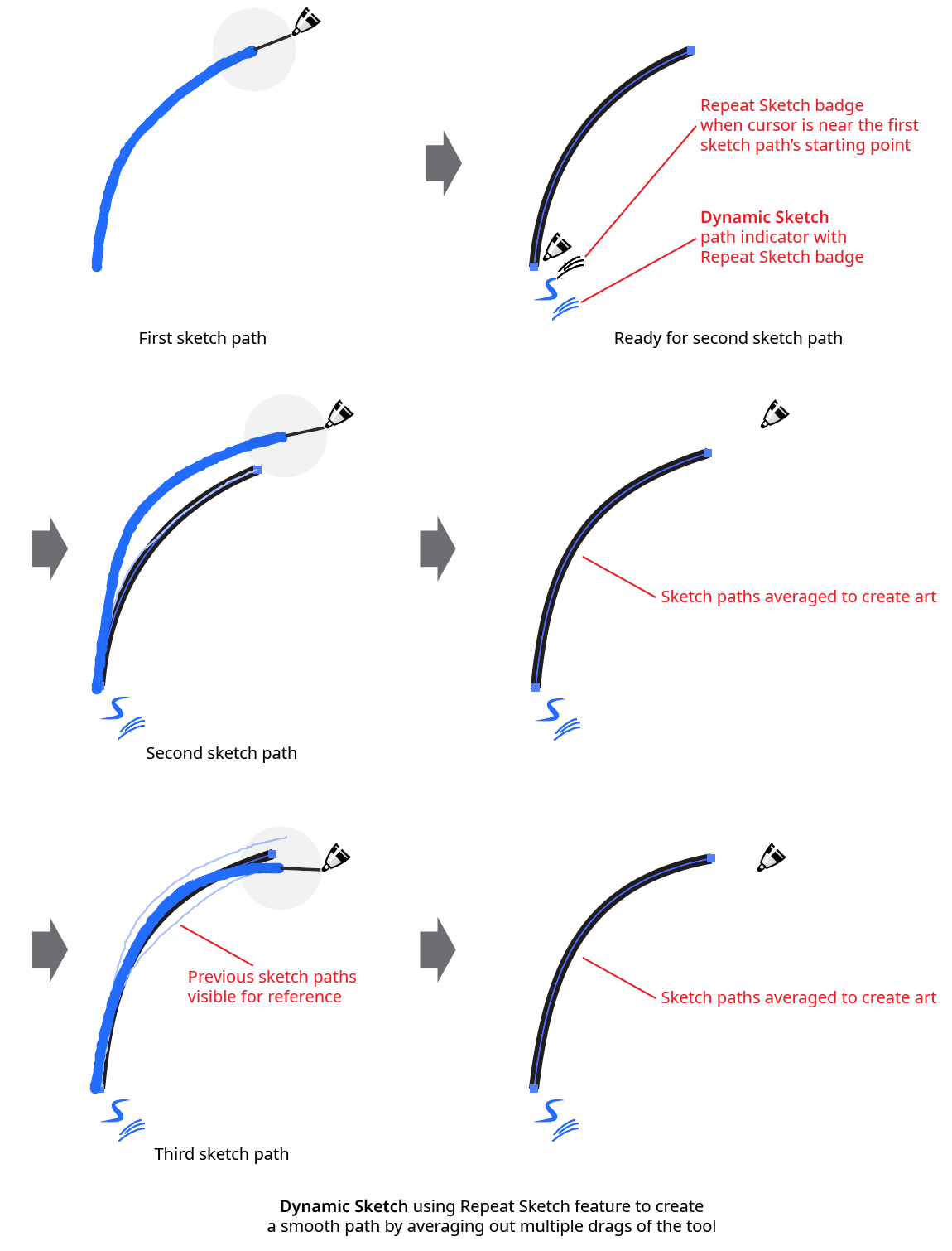
Dynamic Sketch Repeat Sketch Example
Each repeat sketch path must start within a certain distance from the original sketch path’s starting point. This distance has a default value of 50 pixels, but can be customized in the preferences dialog.
By default, if a new sketch path is drawn that does not begin near the start of a repeat sketch path, then the repeat sketch path is automatically finalized (combining all the separate sketch paths into a single one). To finalize an existing repeat sketch path without drawing a new path, use the tool and Shift+Option/ Alt-click on the path indicator, which will change to indicate the function. A finalized path (or one that was drawn when Repeat Sketching was disabled) can be turned back into a Repeat Sketch path using the same method.
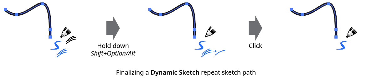
Dynamic Sketch Finalize Repeat Sketch
Repeat Sketching on a closed path will generally result in it becoming open. To average several passes and retain a closed path, see the preference Auto-Detect Continuous Repeated Closed Path Sketches.
4. Edit/Continue/Join Button
Toggles the ability to edit, continue, or join existing paths. See Dynamic Sketch: Tool for information on this mode, which is enabled by default.
5. Intelligent Joining Button
Toggles intelligent path joining mode. When this mode is enabled, sketch paths drawn so that they intersect one or at most two existing, selected paths will be automatically trimmed and joined to that path or paths. The shorter lengths of the paths on either side of the potential join point(s) are the ends of the paths which are trimmed.
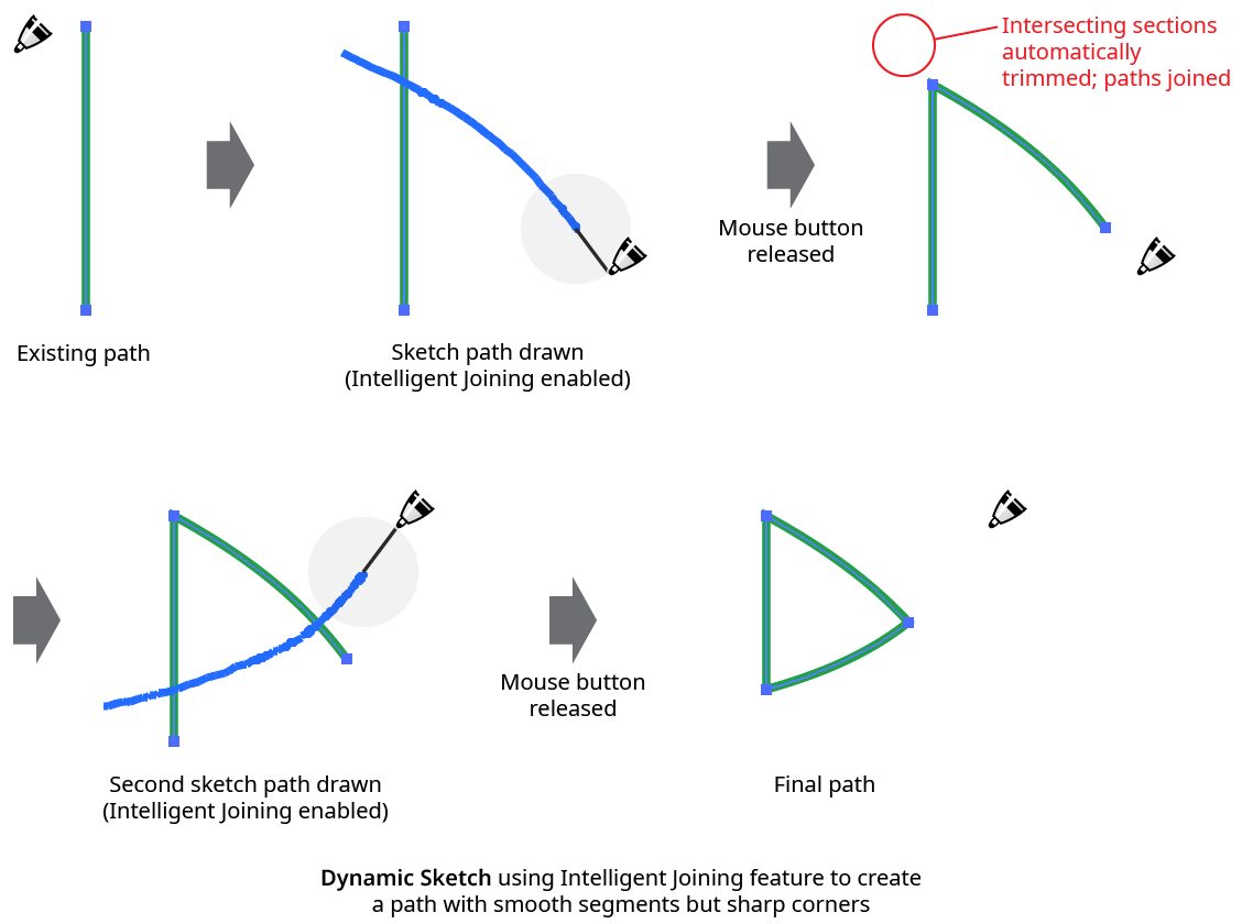
Dynamic Sketch Intelligent Joining Example
Using intelligent joining is generally the easiest method for creating shapes with smooth sides but sharp corners.
6. Gesture Trim Button
Toggles the gesture trim feature on and off. When gesture trimming is enabled, paths or sections of paths (which need not be Dynamic Sketch paths) can be deleted by “scribbling” across them – i.e., sketching a path made up of between two and five short strokes roughly perpendicular to the target path section. This is generally most natural when using a stylus and a short (or no) string.
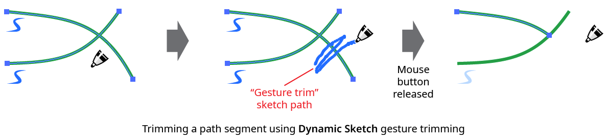
Dynamic Sketch Gesture Trimming
An easier method of trimming a path, which does not require gesture trimming to be enabled, is to hold Shift before starting to drag and then draw a sketch path across the target path(s). When using this method, the cursor will display a small “X” badge, will not use its string (if any), and will annotate its path in a dashed line. As with normal sketch paths, the Option/Alt key may be used to create a straight trimming section.
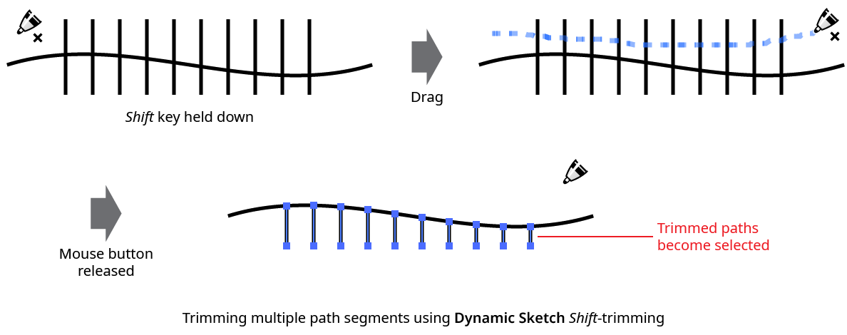
Dynamic Sketch Shift Trimming
If a path which does not cross any other paths is trimmed, the entire path will be deleted. Closed paths can only have one section deleted at a time.
When a path with variable width stroke is trimmed, Dynamic Sketch attempts to retain the width profile(s) of the untrimmed section(s) as they existed prior to the trimming.
7. String Length Specification
Specifies the length of the virtual string used to pull the cursor, from 0 pixels to 500 pixels. Longer strings generally make for smoother curves, but make it more difficult to draw small features. The default value is 50 pixels.
8. Accuracy Specification
Specifies the accuracy level (from 0 to 10) with which the final path conforms to the sketch path (the trail laid down when the tool was dragged on the artboard). Existing Dynamic Sketch paths that are selected can still have their accuracies changed using the slider or value input control. The default accuracy is 5. Depending on the sketch path, changing the accuracy from one value to another nearby value may not always produce a visible change in the path. Higher accuracies will generally require more anchor points.
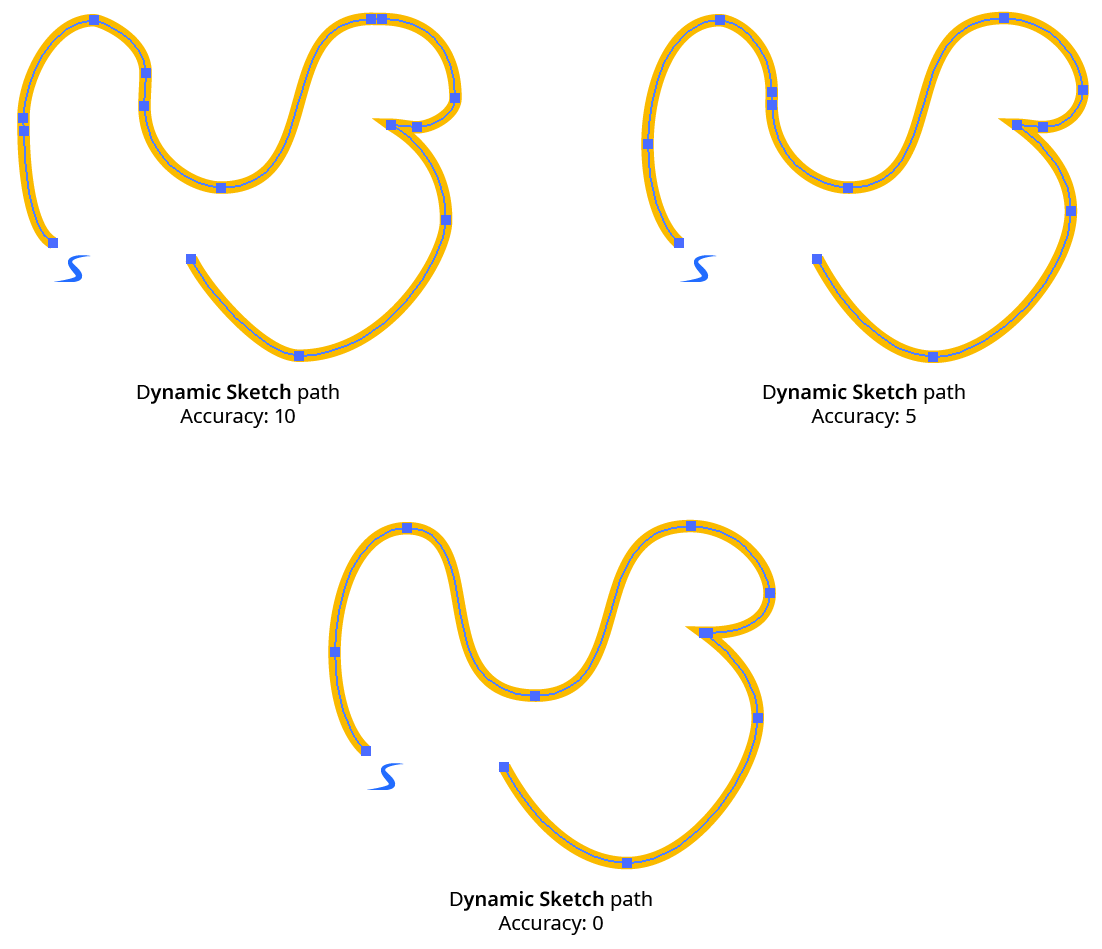
Dynamic Sketch Accuracy Examples
Clicking on the Accuracy icon will change the accuracy value to its default value. The default value to use when doing this can be set by Option/Alt-clicking on the icon.
9. Smoothness Specification
Specifies the smoothness level (from 0% to 100%) of the final path. Existing Dynamic Sketch paths that are selected can still have their smoothness values changed using the slider or value input control. The default smoothness is 50%. Smoothness only has a subtle effect on path shape, but is more important for stroke width (when using variable widths), as generally the cursor speed or stylus parameter used to control the width is difficult to vary in a completely smooth manner:
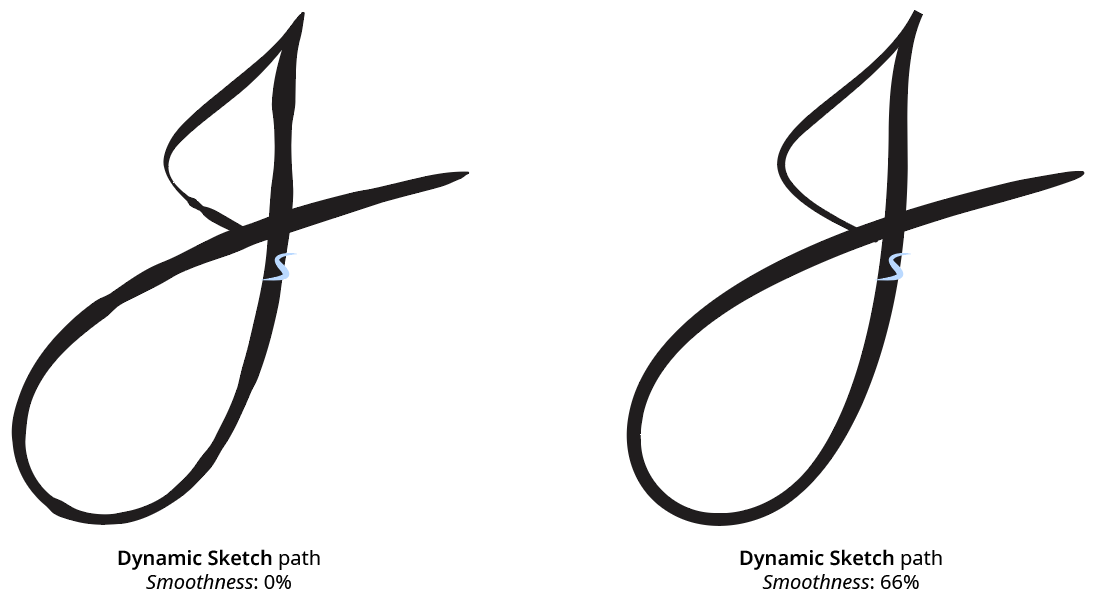
Dynamic Sketch Smoothness Example
Clicking on the Smoothness icon will change the smoothness value to its default value. The default value to use when doing this can be set by Option/Alt-clicking on the icon.
10. Width Control Dropdown Menu
This item, and all items below it, are only visible on the panel if the panel flyout menu item Show Input Graph has been enabled. The Width Control dropdown menu specifies how the stroke width of the path is determined. When the menu is set to None, the width is taken from the current appearance that is applied any new path art (unless the Dynamic Sketch preference New Paths Have Basic Appearance is enabled; in that case, the path will not include multiple strokes or fills, or live effects). When the current appearance includes a variable width stroke profile, the variable width is, by default, previewed in real time as the sketch path is being drawn (unlike the native Pencil tool).
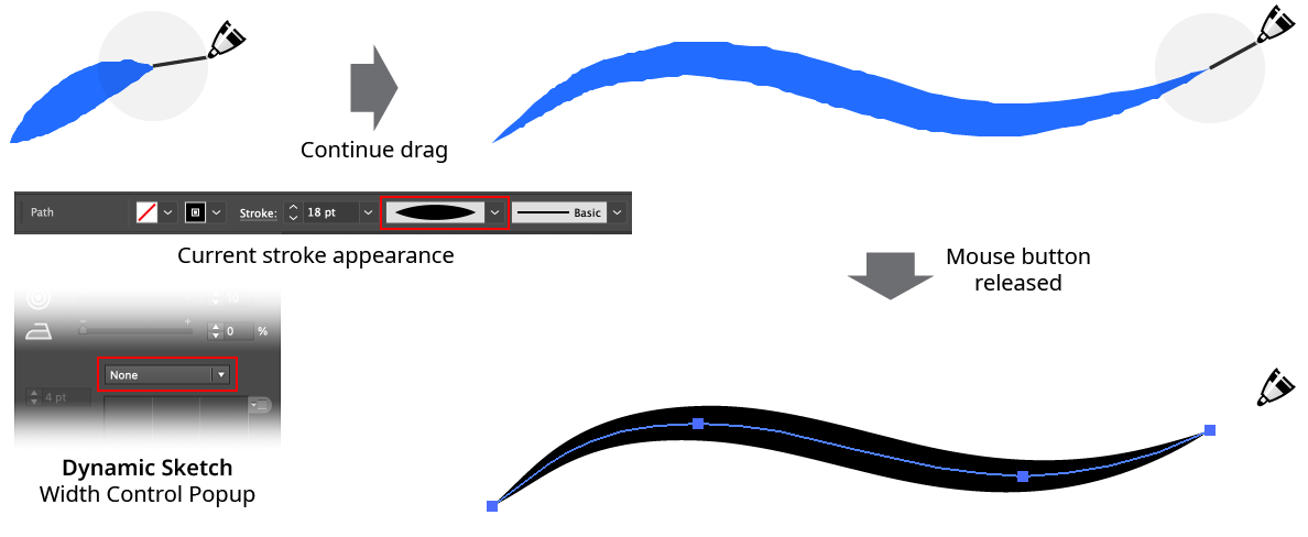
Dynamic Sketch Variable Sketch Width Profile Preview
If the Width Control dropdown menu is set to Speed (the default), the stroke width is determined by the speed with which the cursor was moved over the artboard along the length of the path, in conjunction with the graph. If set to one of the stylus parameters (Stylus Pressure, Stylus Wheel, Stylus Tilt, Stylus Bearing, or Stylus Rotation), then the stroke width is determined by the corresponding stylus parameter as it was recorded along the path, again in conjunction with the graph.
11. and 12. Maximum and Minimum Stroke Weight Values
These values specify the largest and smallest stroke weights that the variable width stroke will contain. For example, if the maximum value is set to 12 pt, the minimum value is set to 1 pt, the Width Control dropdown menu is set to Stylus Pressure, and the graph is the default linear graph, then places along the path where the stylus was being held down with maximum pressure would have a stroke weight of 12 pt, while places where the stylus had minimum pressure would have a stroke weight of 1 pt. The values can be changed after the path is drawn, if it remains selected.
13. Width Control Graph
Specifies the relationship between the maximum and minimum values and the input parameter. The horizontal axis represents the input parameter (for example, stylus pressure) from 0% to 100%, while the vertical axis represents the stroke weight, specified by the maximum and minimum value inputs. With the default diagonal line, the relationship is a linear one. Nodes on the curve may be moved simply by clicking and dragging them. A new node may be added by clicking at a spot along the curve which does not already have a node. Nodes (except the ones at the beginning and the end of the curve) may be deleted by dragging them off the graph area.
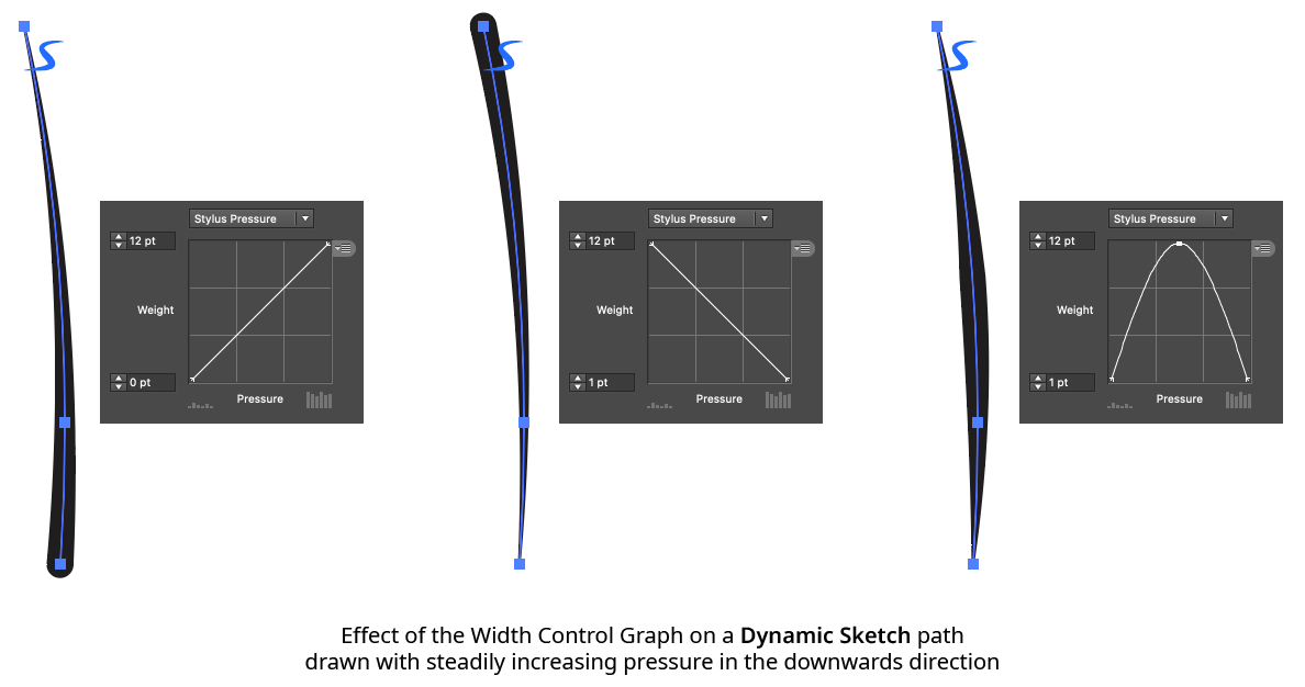
Dynamic Sketch Graph Example
14. Width Control Graph Preset Menu
Provides access to saving, managing, and applying graph settings.
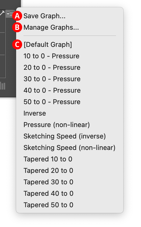
Dynamic Sketch Graph Preset Menu
A. Save Graph...
When you save the current graph, its nodes and maximum and minimum values are captured to an internal file which can be recalled later. The file name may be specified.
B. Manage Graphs...
Brings up the Manage Graphs dialog, which lets you rename, delete, import, or export graph files:
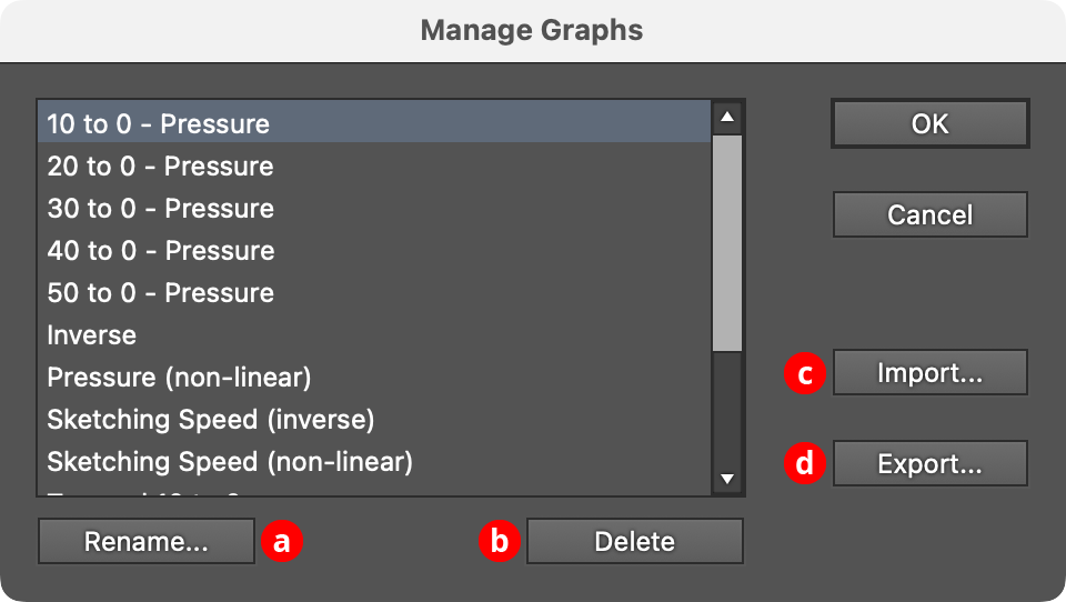
Dynamic Sketch Manage Graphs Dialog
a. Rename: Allows the selected graph file to be renamed.
b. Delete: Removes the selected graph file(s).
c. Import...: Imports a previously-exported graphs package file of type “.dsg” using the standard operating system open file dialog.
d. Export...: Exports the selected graph(s) into a graphs package file of type “.dsg” using the standard operating system save file dialog. This file could be used as a backup or passed to another user.
C. Graphs List
Choosing a graph file from this list will update the graph to the values saved within that file (or, the case of “[Default]”, to the default graph).
Dynamic Sketch Panel Flyout Menu
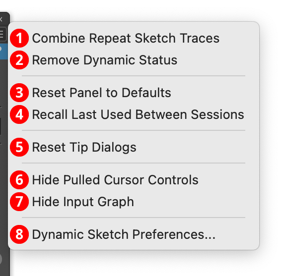
Dynamic Sketch Panel Flyout Menu
The Dynamic Sketch panel flyout menu items are contextually sensitive and all items may not be available, depending on the current selection.
1. Combine Repeat Sketch Traces...
Combines the repeat sketch traces of the selected Dynamic Sketch path, averaging them to create a single sketch path. This is the same as Shift+Option/Alt-clicking on the path indicator icon with the tool.
2. Remove Dynamic Status
Converts the selected Dynamic Sketch paths into “regular” paths. Once this is done, their accuracy, smoothness, and width input settings can no longer be changed. Most operations made to a Dynamic Sketch path outside the tool (scaling or rotating it, adding points to it, etc.) will automatically remove the dynamic status.
3. Reset Panel to Defaults
Resets all panel controls (including the width input graph) to their default settings.
4. Recall Last Used Between Sessions
When enabled, the Dynamic Sketch panel’s state will be retained between launches of Illustrator.
5. Reset Tip Dialogs
If one or more of Dynamic Sketch’s tip dialogs have been suppressed using the Don’t show again checkbox, choosing this menu item will re-enable them.
6. Hide Pulled Cursor Controls
The pulled cursor string length slider and input value can be shown or hidden on the panel using this menu item. When the controls are hidden, the menu item will change to Show Pulled Cursor Controls.
7. Hide Input Graph
The entire lower width control section of the panel can be toggled using this menu item. When hidden, the panel takes significantly less vertical space. In this state, the menu item will change to Show Input Graph.
8. Dynamic Sketch Preferences...
Brings up the Preferences dialog.