Remove Points
![]() VectorFirstAid Panel
VectorFirstAid Panel
 InkScribe Tool
![]() PathScribe Panel
PathScribe Panel
![]() Smart Remove Brush Tool
Smart Remove Brush Tool
 Reposition Point Tool
 AG Utilities Live Effects
Illustrator Location:
Illustrator Main Menu > Window > Astute Graphics > VectorFirstAid
Each convenience operation has various parameters, which are specified in the preferences dialog (see VectorFirstAid: Preferences). By holding down the Option/Alt key while clicking a convenience operation button, a small dialog will come up allowing those parameters to be changed before the operation is made. These new parameters apply to that single use of the operation only.
3. Super Smart Remove Points Button
Reduces the number of anchor points in the selected paths while attempting to maintain their shapes. There are two parameters.
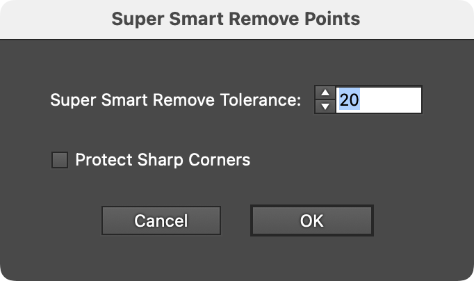
VectorFirstAid Super Smart Remove Points Parameters
a. Super Smart Remove Tolerance: Ranges from 1 to 100. The higher the tolerance, the more anchor points are removed, but the more the geometry of the path may change.
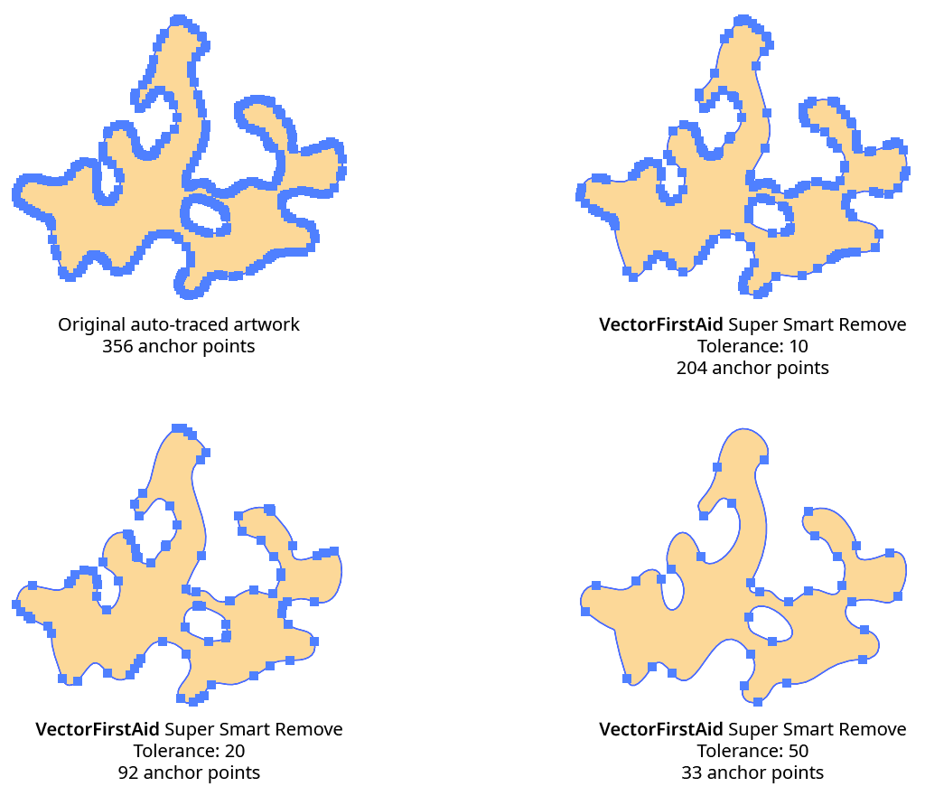
VectorFirstAid Super Smart Remove Example
b. Protect Sharp Corners: Determines whether corner type anchor points where the path has a sharp change in direction will be considered for removal. Enabling this setting lets you use a high tolerance to remove many anchor points without disturbing sharp corners, where the geometry of the path is usually more critical:
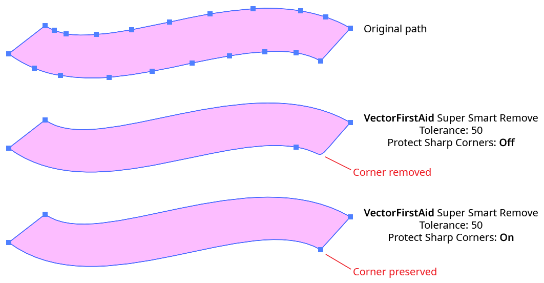
VectorFirstAid Super Smart Removal Protect Sharp Corners
4. Rejoin Paths Button
Rejoins paths which have been split apart into multiple segments back into a single path (or, if discontiguous, into multiple paths).
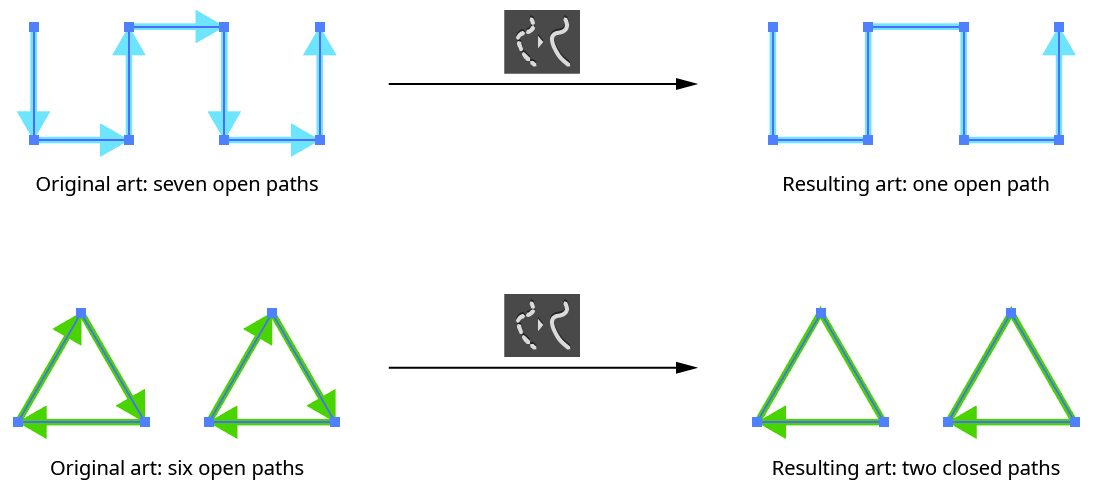
VectorFirstAid Rejoin Paths Example
The Rejoin Paths operation takes several parameters:
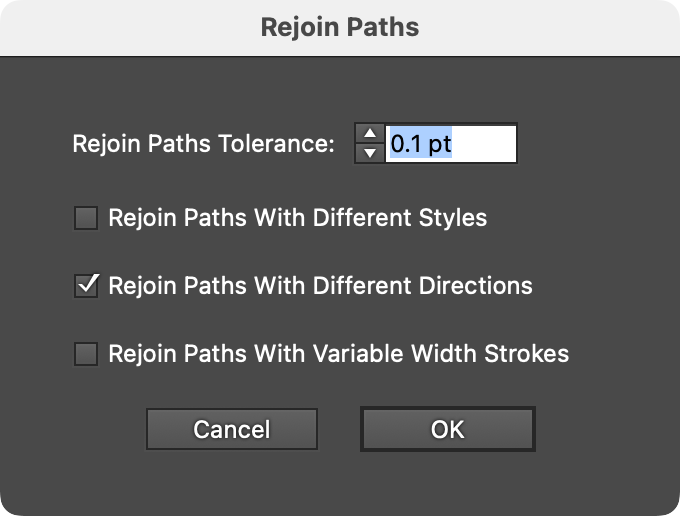
VectorFirstAid Rejoin Paths Parameters
a. Tolerance: The maximum distance that the endpoints of each segment can be from each other and still be joined, ranging from 0 to 6 pt. The default is 0.1 pt.
b. Rejoin Paths With Different Styles: Whether paths with different styles are allowed to be rejoined. When enabled, the style of the final path is taken from the section which is highest in the stacking order.
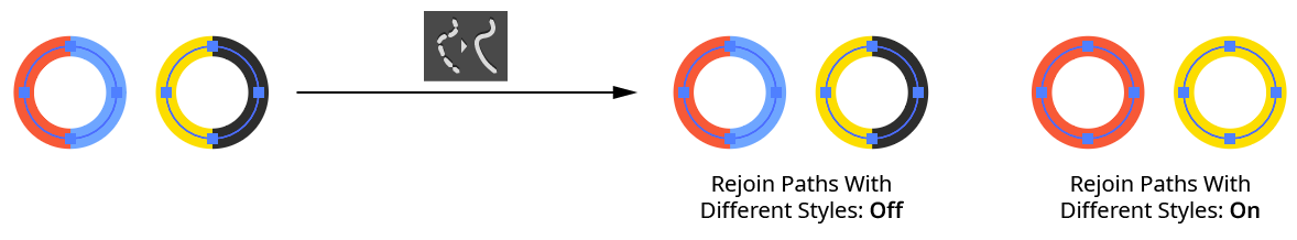
VectorFirstAid Rejoin Paths with Different Styles
c. Rejoin Paths With Different Directions: Whether paths that touch head-to-head or tail-to-tail are allowed to be rejoined. When enabled, the direction of the final path is taken from the section which is highest in the stacking order.
d. Rejoin Paths With Variable Width Strokes: Whether paths stroked with a variable width stroke are allowed to be rejoined. When enabled, the variable width profile for the final path is taken from the section which is highest in the stacking order.
If multiple sections are eligible to be joined, VectorFirstAid uses the one that results in a path with the smallest change in angle:
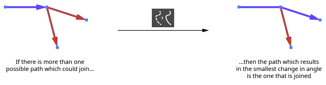
VectorFirstAid Rejoin Paths Angle Selection
5. Combine Point Text Objects Button
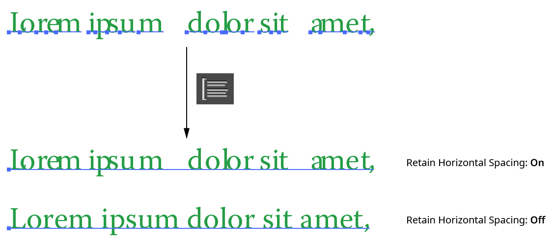
Combines the selected point text objects into as few point text object as possible while maintaining the position of all characters. Text can be combined both horizontally and vertically, but must be at the same angle.
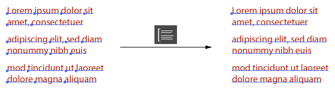
VectorFirstAid Combine Point Text Example
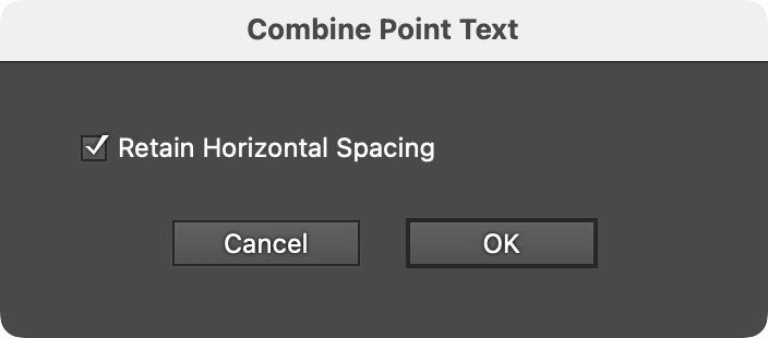
VectorFirstAid Combine Point Type Parameters
A single parameter, Retain Horizontal Spacing, controls how horizontal gaps between characters and words are handled. When enabled (the default), kerning is modified and/or space characters are added to precisely duplicate the original spacing of the text. When disabled, the spacing is normalized when possible, to give the text the look it would have if it were not tracked or kerned. Gaps wider than a single space character will still be retained as a single space. This setting can be useful when opening certain PDF files where the text has been broken into individual characters with corrupted spacing:
VectorFirstAid Combine Point Text - Retain Horizontal Spacing
6. Replace All Missing Fonts Button
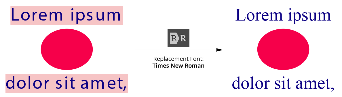
Replaces all missing fonts in the document with a specified font. Whether replacing a single missing font, or because the exact font is not critical because it will be changed later, this is much faster than going through the Find/Replace Font dialog.
VectorFirstAid Replace All Missing Fonts
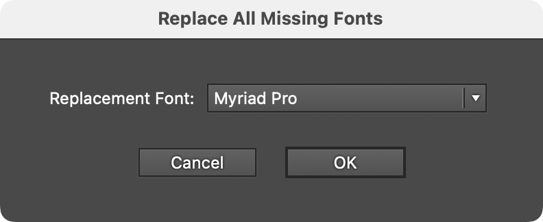
The one parameter is the replacement font.
VectorFirstAid Replace Missing Fonts Parameters
7. Unoutline Text Button
Converts the selected type that has been outlined (converted to paths) back into editable text, if possible. VectorFirstAid refers to this process as “Unoutlining.” The first time this operation is used after installing the plugin, VectorFirstAid will open a new, temporary document and scan the currently installed fonts to build an internal database of their glyphs. This may take 5 to 20 minutes or even longer, depending on how many fonts are installed and their types. In particular, the SF Pro font family contains very high numbers of glyphs and will slow down the operation. However, the data is saved out to files, so this process only needs to be done once.
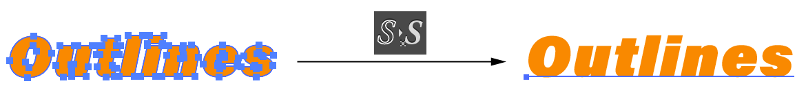
VectorFirstAid Unoutline Text Example
The Unoutline Text operation can handle most linear transformations of the outlines, including scaling (except that which reverses path direction), rotation, and shearing.
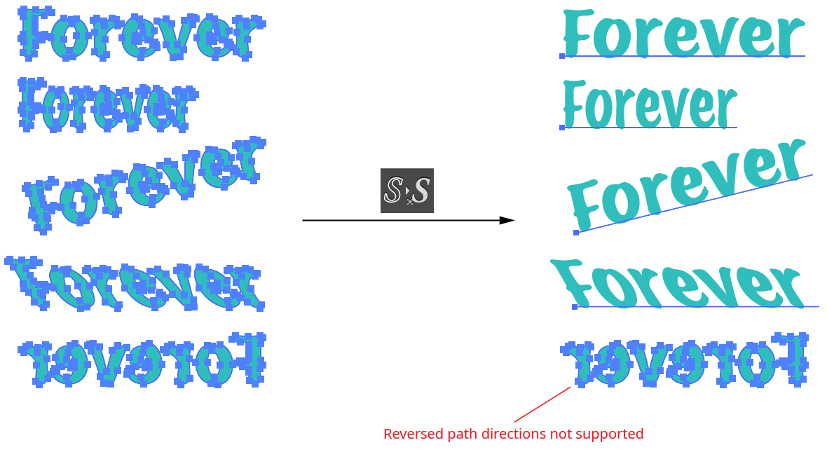
VectorFirstAid Unoutline Text Example 2
If type cannot be unoutlined, it may be due to several reasons. First, the correct font may not be present on the system. Second, the path outlines may have been altered in some way, making them different from the original outlines. For example, the starting point of the paths may have changed, or individual points may have been deleted or moved slightly. Finally, the Unoutline Text operation is not supported for fonts which contain more than 7,500 glyphs, with the exception of the SF Pro family. However, support for the SF Pro family is limited to the first 14,000 glyphs for each font.
The Unoutline Text operation takes several parameters:
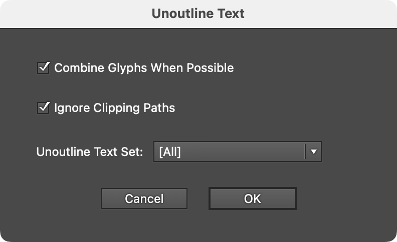
VectorFirstAid Unoutline Text Parameters
a. Combine Glyphs When Possible: Enabled by default, this option combines the individual glyphs which have been recognized into as few point text objects as possible. Otherwise, each glyph is left as a separate point text object.
b. Ignore Clipping Paths: Ignores paths which are set as clipping paths for the purposes of conversion.
c. Unoutline Text Set: Specifies a pre-configured set of fonts to use when recognizing the outlined paths. Checking these outlines against every possible font can take some time, and might result in the conversion to a different font than expected (due to the fact that some simple glyphs, such as lower case l’s, are identical across many sans serif fonts when linear transformations are allowed). For this reason, if the font of the outlined text is already known, VectorFirstAid can use this information to ignore other fonts and recognize the text more quickly and reliably. Unoutline Text Sets are configured through the Preferences dialog (see VectorFirstAid: Preferences). A quicker method is to simply some select live text along with the outlined text before using Unoutline Text. In this case, VectorFirstAid will only consider the fonts present in the selected live text, ignoring any specified Unoutline Text Set.
If new fonts are installed after VectorFirstAid has created its font database, the database will be updated after the button is clicked. A progress dialog will be shown.
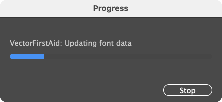
VectorFirstAid Font Database Update
If artwork other than outlined text is selected when performing an Unoutline Text operation, it generally causes no harm, because most artwork paths are unlikely to match the shape of a glyph. However, this is not true for basic shapes such as rectangles and circles, which are used in hundreds of fonts for glyphs such as hyphens, dashes, bullets, and so on. Since text, when outlined, always results in compound paths, VectorFirstAid will display a warning if a non-compound simple shape exists in the selection:
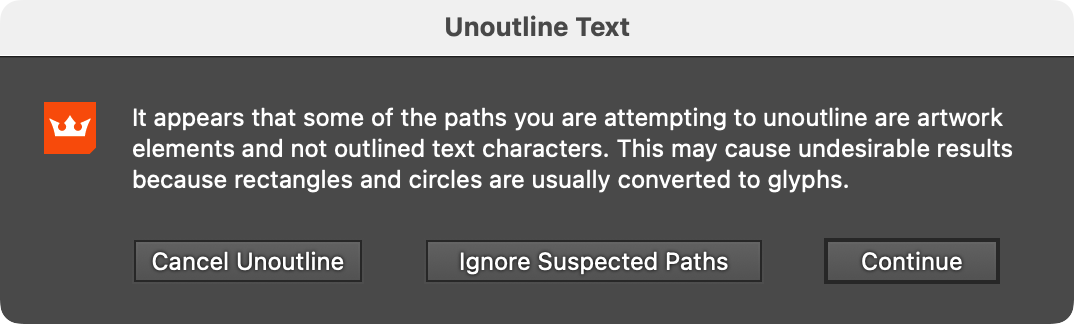
VectorFirstAid Unoutline Warning
Illustrator Location:
Advanced Toolbar > Pen Stack > InkScribe Tool
When a path is at least partly-selected, its existing anchor points may be selected, moved, modified, or removed. As some keypresses can change depending on the way the InkScribe preferences are set, the Astute Buddy panel is the best reference, as it shows current keypresses taking into account the current preference settings.
Clicking on an anchor point selects that point; the virtual panel annotation (if enabled) is moved to that point. If the point is at one end of an open path, then the path becomes the active path and can have additional points added to it. Shift-clicking has the same effect unless the preference Option/Alt-Click On Point to is set to Select. (In that case, Shift-clicking removes the point without adjusting handles to keep the curve shape).
Option/Alt-clicking on an anchor point Smart Removes the point (unless the preference Option/Alt-Click On Point to is set to Select). When a point is Smart Removed, the handles of the adjacent anchor points are extended or retracted so the resulting path shape is as close to the original as possible. To remove a point without adjusting any handles, Shift+Option/Alt-clicking may be used. The Smart Remove button on the panel or virtual panel can also be used to remove a point.
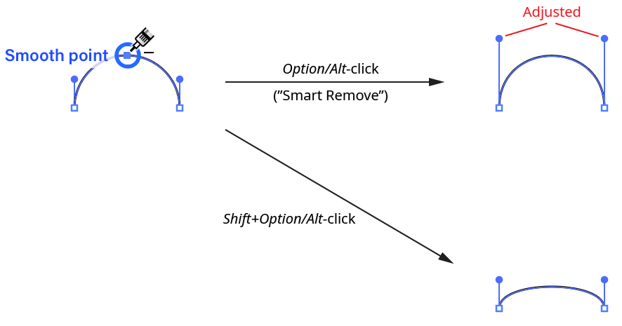
InkScribe Point Removal
Doubleclicking an anchor point (or one of its handles) on a selected path converts the point’s type from corner to smooth or vice versa. When a smooth point is converted to a corner point, handles (if any) are not moved. When a corner point is converted to a smooth point, and both handles exist, each handle swings away from the other in equal amounts until they are 180° apart (unless a handle was clicked, in which case only the clicked handle moves):
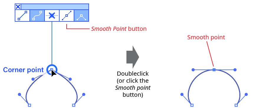
InkScribe Point Type Change
If the point did not have two handles originally, new handles are added. The Smooth Point or Corner Point buttons on the panel or virtual panel can also be used to change a point’s type.
Dragging an anchor point on a selected path moves it. InkScribe only moves a single anchor point at a time (to move multiple points, Astute Graphics’ PathScribe tool may be used). To move the point in a direction constrained to 45° increments around the general constrain angle from its original position, hold down the Shift key. If at least one of the point’s adjacent segments is straight, press the L key during the drag to toggle linear constrain mode, in which the point’s movement is constrained to the line formed by the straight segment(s).
Option/Alt-dragging an anchor point on a selected path, by default, defines the Out handle (as per the native Pen tool). If the point is a smooth point, the In handle will also move to remain opposite it. To define the Out handle on an existing point, Option/Alt must be held down before the drag starts. If the tool preference Option-Alt-Drag a Point to is set to Constrain Distance by Factor, then Option/Alt-dragging instead moves the anchor point from its original location by a multiple of the Distance Factor. For example, if the Distance Factor is set to 10 px, then the point will be moved 10 px, 20 px, 30 px, etc., but not in-between values. Distance constraining works only if the Option/Alt key is held down after the drag has started.
Illustrator Location:
When no handles are selected, the panel appears in Point Mode:
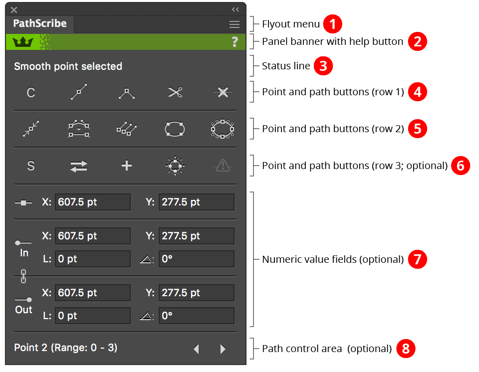
PathScribe Panel point mode
1. Flyout menu
See PathScribe Panel: Flyout Menu.
2. Panel banner
The help button on the right opens the help documentation in the Astute Manager. If this does not automatically appear, please ensure your Astute Manager is running first.
Click on the other area of the color bar to activate the PathScribe tool. This is a quick method of locating the tool within the default Advanced toolbar or a custom toolbar.
3. Status Line
Shows information about the current selection, for example “7 points selected”. When exactly two anchor points are selected, the status line shows the distance between them, and displays a small button which allows you to average the points’ positions, to make them coincident:
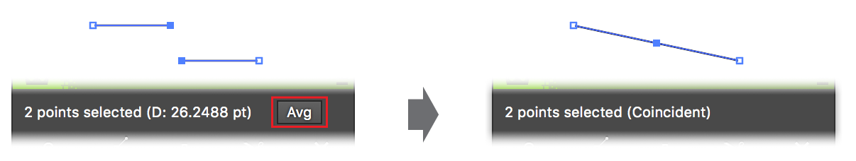
PathScribe Panel two point average
Option/Alt-clicking on the status line when showing the distance between two points will copy the distance value to the system clipboard.
If the third row of buttons is hidden, the status line also contains a redundant point indicator/button (see below). Finally, the status line will also indicate what you are editing during a drag operation.
4. Point and Path Buttons (row 1)
a. Connector Point Recognition Button: Toggles Connector Point recognition. When the “C” symbol is dim, connector point recognition is off and the PathScribe tool will not afford any special handling to points which qualify as connectors.
b. Smooth Point Button: Changes all selected anchor points to smooth points. By default, this also adds new handles to these points so they all have two opposed handles. This can be very useful for creating a path that runs smoothly through the points:
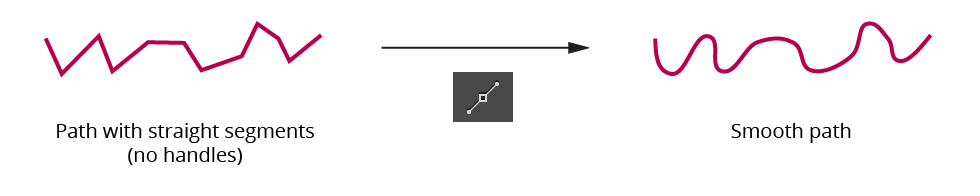
PathScribe smooth point button example
The algorithm that PathScribe uses to create new handles is as follows: If a point already has one handle, its second handle is created by mirroring the existing handle. If a point has no handles, the new handle angle is calculated by bisecting the angle formed by the previous point, the point in question, and the next point, and taking its perpendicular. The new handle length is calculated by taking the lesser of the distances from the point in question to the previous and next points, and multiplying by the smoothing ratio (set in the Preferences dialog). Handles of endpoints of open paths, if created, are adjusted to aim towards the next/previous handle.
To change selected anchor points to smooth points without adding handles, hold down Option/Alt when clicking the button.
c. Corner Point Button: Changes all selected anchor points to corner points. No handles are created or changed.
d. Split Path Button: Splits the path(s) at the selected points, just as clicking on them with the Scissors tool would. Both new endpoints get a copy of the original point’s handles.
e. Smart Remove Point Button: Removes the selected point(s) from the path while attempting to keep the curve as close as possible to its original shape. This is achieved by adjusting the lengths (but not angles) of the handles on either side of the removed points. To remove points without handle adjustment in the manner of the Delete Anchor Point tool, hold down Option/Alt while clicking the button.
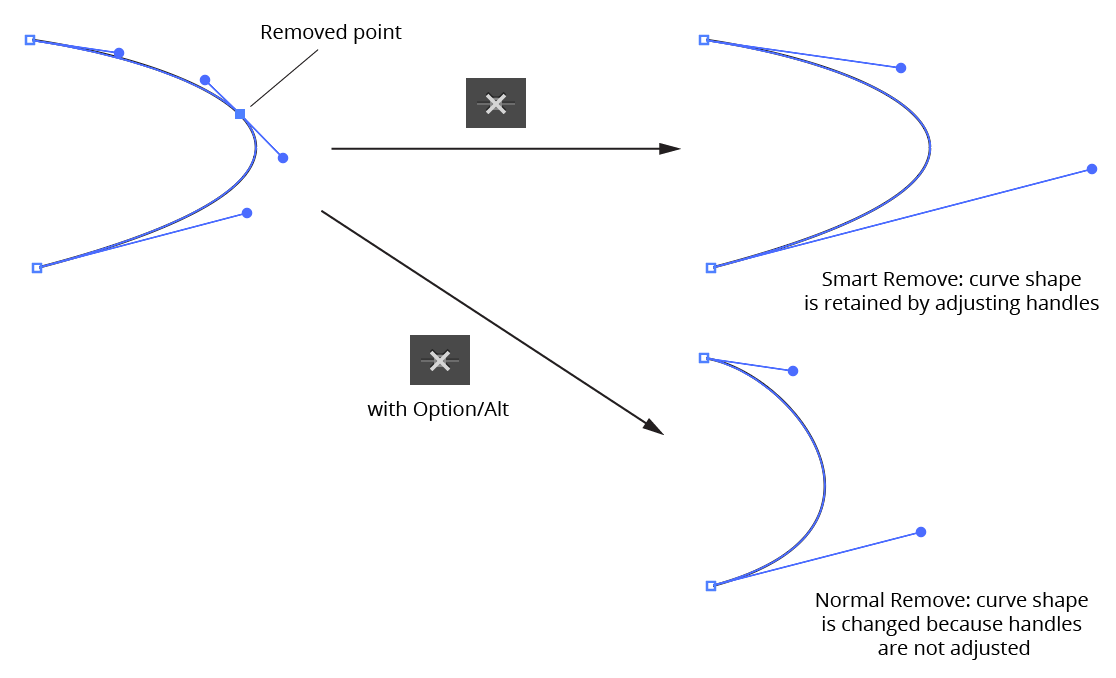
PathScribe Panel smart point remove
When anchor points are selected, you can use the keypress assigned in the Keyboard Shortcuts dialog for “Increase Diameter” (by default, the right bracket key – ]) as a shortcut for the Smart Remove Point button.
When Shift is held down while the button is clicked, PathScribe removes straight segment corners. To utilize this function, two or more adjacent anchor points must be selected, the first and last of which are adjacent to a straight segment (or at the end of an open path); the segments do not necessarily have to form a “nice” corner. The selected anchor points are replaced by a single anchor point at the intersection of the outer straight segments:
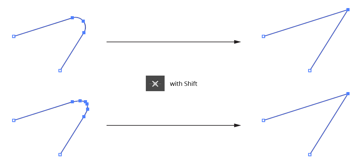
PathScribe removes handles
5. Point and Path Buttons (row 2)
a. Retract Handles Button: Retracts all of the handles on the selected point(s). Point types are not changed. Holding down Option/Alt while clicking the button activates an alternate function: it swaps the positions of the in and out handles on each selected point.
b. Retract Segment Handles Button: Retracts handles from all selected path segments. Point types are not changed.
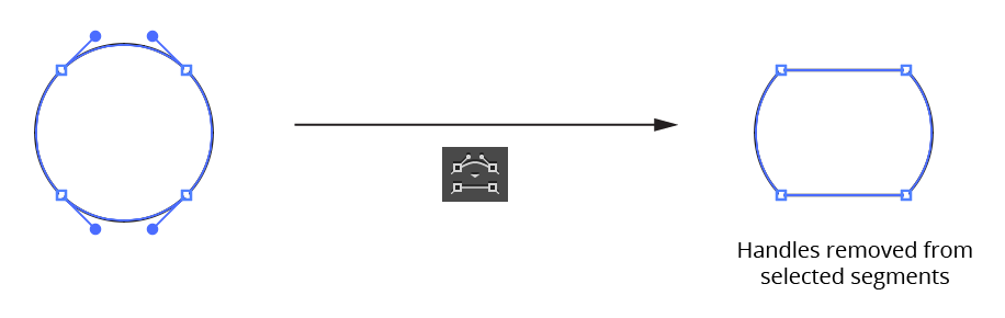
PathScribe Panel remove handles from segments
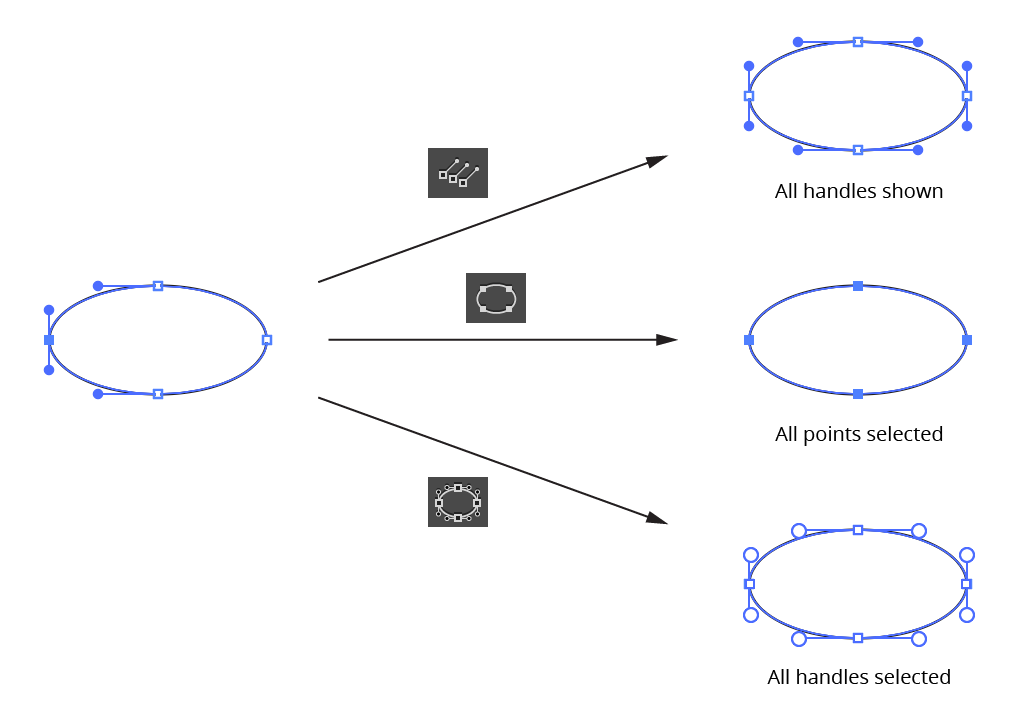
c. Show Handles Button: All paths or compound path subpaths which are at least partly selected will have all handles made visible (note that this deselects all anchor points and instead selects all path segments).
d. Select Path Points Button: Selects all points on all paths which are at least partially selected.
e. Select All Handles Button: Selects all handles on all paths which are at least partially selected; PathScribe then enters Multi-Handle mode.
PathScribe second row icons
6. Point and Path Buttons (row 3)
This row can be shown or hidden using the PathScribe panel flyout menu.
a. Smart Smooth Button: Enables or disables “Smart Smooth”, a feature of the PathScribe tool which allows you to convert a corner point into a smooth point simply by dragging one of the point’s handles to be opposite the other (within a certain tolerance). A small red “S” annotation is drawn over points which are being aligned this way. The threshold angle value can be specified in the Preferences dialog.
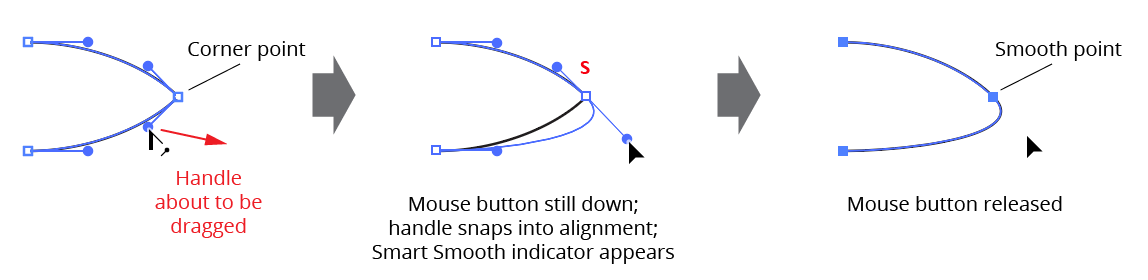
PathScribe panel smart smooth
b. Reverse Path Direction Button: Reverses the direction of any selected paths or subpaths. This will generally only produce a visible change to the artwork if a subpath of a filled compound path is reversed or if the path is being stroked by an asymmetric brush:
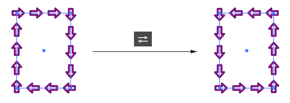
PathScribe Reverse Path Direction Button
When the third row of buttons is hidden, the “Reverse Path” command can still be accessed through the PathScribe panel flyout menu (see below).
c. Add Points to Selected Segments Button: Adds anchors points to every selected segment of every selected path. The number of points added and algorithm used to add them are taken from the last-used settings. To open the dialog which enables you to edit these values, Option/Alt-click on the button.
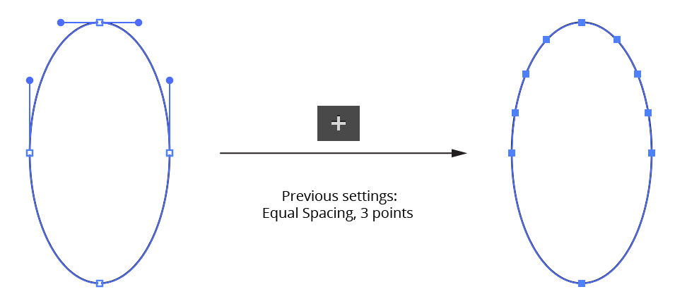
PathScribe Add Points to Selected Segments Button
When the third row of buttons is hidden, the “Add Points” command can still be accessed through the PathScribe panel flyout menu (see below).
d. Move Points to Tangencies Button: Moves anchor points on the selected paths to positions along the path where the angle of the path as it passes through the anchor point is tangent to the horizontal or vertical axes (taking into account the current constrain angle).
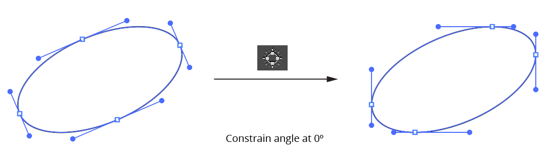
PathScribe Move Points to Tangencies Button
Holding down Option/Alt when clicking the button changes its functionality: new anchor points are placed at the tangent positions, but the existing anchor points are retained.
Holding down Shift when clicking the button also changes its functionality: Only selected points are moved to tangencies.
When the third row of buttons is hidden, the “Move Points” command can still be accessed through the PathScribe panel flyout menu (see below).
e. Remove Redundant Points Button: Removes all redundant points from all selected paths. If the button is disabled (dim), no redundant points exist. A redundant point, also known as a doubled point, is defined as the latter of two consecutive anchor points on a path that have exactly the same X and Y coordinates and don’t have handles in the (zero-length) segment between them. They are often created after using the PathFinder functions or after using Object > Path > Outline Stroke, and despite not changing the shape of the path, can cause problems when performing additional functions such as offsetting. You can highlight the locations of redundant points when using the PathScribe tool by enabling the corresponding preference (see PathScribe Preferences).
When the third row of buttons is hidden, the button will appear on the right side of the top status line. Due to space considerations, the icon uses a small exclamation point rather than the full icon:
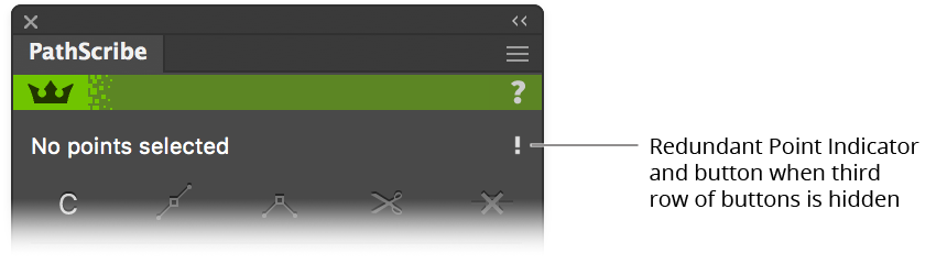
PathScribe Remove Redundant Points Button
7. Numeric Value Fields
This area can be shown or hidden using the PathScribe panel flyout menu.
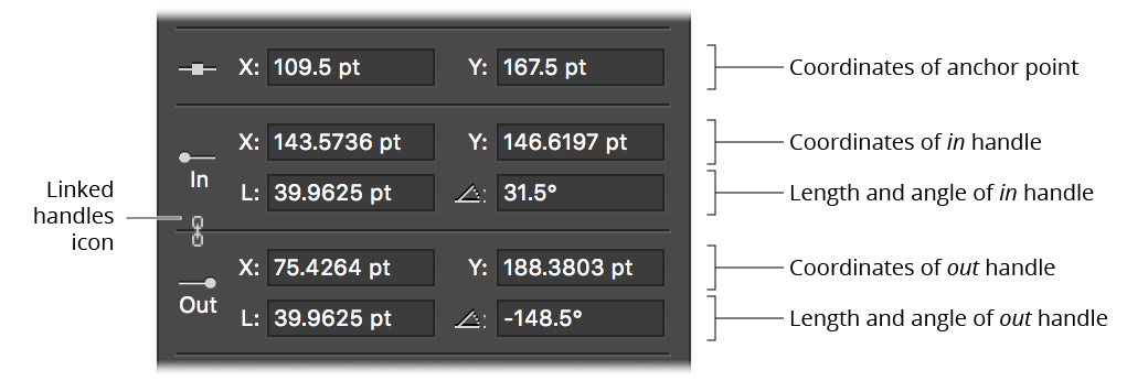
PathScribe Numeric Value Fields
When an anchor point is selected, the numeric value fields becomes active, reflecting the X and Y coordinates of the anchor point and the coordinates, lengths and angles of its two direction handles. You can make edits to any of the fields by simply typing in a new value and pressing Return/Enter or Tab. Like other numerical entry fields in Illustrator, you can use any units you wish (except in the angle fields) and one math operator.
The linked handles icon appears when editing a smooth point, as a reminder that edits to the coordinates or angle of one handle will also affect the other handle (if it exists).
You can specify the number of digits that are displayed after the decimal point through PathScribe’s Precision preference.
When more than one anchor point is selected, fields which are blank indicate that multiple values are present. You can still type a new value into the field, thereby assigning it to all selected anchor points/ handles. Or, for the anchor point fields, you can Shift-click on the anchor point icon to average all values in both fields; or Shift-click on the “X:” or “Y:” labels to average only the corresponding value.
When the Show Anchor Point Coordinate Ranges preference is enabled, mixed values will be instead displayed in the anchor point coordinate fields as a value (in blue) representing the difference between the highest value and the lowest value:
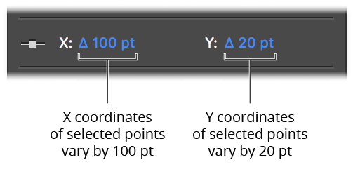
PathScribe Coordinates of points
Clicking on the range will allow you to enter a new value, just as with the preference disabled. Values which are too small to display with the current precision are displayed using scientific notation, e.g. 3.12E-06, where “E-06” means “×10–6” (one-millionth).
8. Path Control Area
This area can be shown or hidden using the PathScribe panel flyout menu. In Point Mode, the path control area has three different appearances:
a. When the selection consists of more than one path, the path control area shows the total number of selected paths and the number of each type (closed, open, or single-point). Each subpath of a compound path is reported separately.
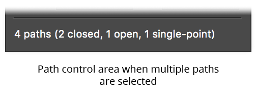
PathScribe Panel Path Control Area multiple paths
b. When the selection consists of a single path, and either multiple points or no points on the path are selected, the status line shows the type of path and a Select Point 0 button. Because Illustrator numbers points starting at zero and continuing consecutively in the direction of the path, clicking the button will therefore select the first point on the path. By default, the selected point will be briefly highlighted with a small magenta dot to make it easier to locate. If the Highlight Panel-Selected Points preference is disabled, you can still highlight the point on a use-by-use basis by holding down Option/Alt when clicking the button.
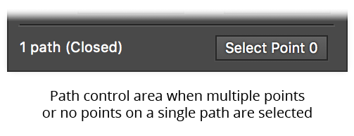
PathScribe Panel Point Control Area Show Point
c. When the selection consists of a single point on a single path, the path control area shows the index of the point, the range of indices on the path, and two buttons that let you change the point that is selected. To move to (i.e., select) the previous or next point on the path, click the Previous point or Next point button. Clicking the Next point button or Previous point button while the last point of an open path is selected will wrap around to the other end.
Holding down Shift while clicking the Next point or Previous point buttons will move ahead or back 10 anchor points (if the path has more than 10 points).
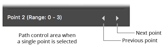
PathScribe PCA Previous Next buttons
Again, the selected point will be briefly highlighted by default.
Illustrator Location:
After selecting the Smart Remove Brush tool, first adjust its size (either through the preferences dialog or by using the keys assigned to “Increase Tool Diameter” and “Decrease Tool Diameter” in Illustrator’s Keyboard Shortcuts dialog, just as with other brush tools). The circle surrounding the crosshair cursor reflects the current size of the brush.
To use the tool on a path, simply brush over the areas of the selected path(s) where you want to remove anchor points. Each path’s new virtual shape is continually displayed in red, allowing you to see how much it has changed with the removal of the points.
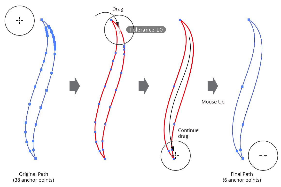
Smart Remove Brush Tool Overview
For each anchor point that falls within the brush circle, the tool decides based on its current parameters whether it will be removed or not (in all cases, when a point is removed, the path’s geometry is kept as close to the original as possible). First, if an anchor point is selected, and the Shift key is being held down, the point is considered protected and is never removed. Second, if the Command/Ctrl key is being held down, the point is always removed in a “non-smart” manner (i.e., surrounding handles are not adjusted).
Then, if the Ignore Tolerance preference is enabled, the point is always removed. Otherwise, the amount of distortion that would result if the point were removed is calculated and compared to the current tolerance value. If the amount is below the tolerance value, the point is removed.
It is best to start with a low tolerance value and slowly increase it if the path still has too many anchor points. The default tolerance of value of 10 generally works well with most paths, but higher values can aggressively remove more anchor points when exact path geometry is not critical.
While dragging the Smart Remove Brush tool, several keys may be pressed to change parameters on the fly or change functionality. As with all Astute tool keypresses, these will be indicated on the Astute Buddy panel.
Shift: Protects selected points (keeps them from being removed). This is useful for preserving specific anchor points without having to carefully dodge around them with the brush:
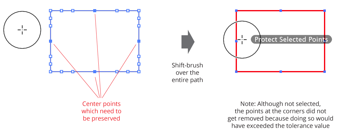
Smart Remove preserving specific anchor points
Option/Alt: Temporarily inverts the Ignore Tolerance preference. That is, if Ignore Tolerance is disabled (tolerance is being used), and the
Option/Altkey is pressed, the tool will temporarily ignore the tolerance value, removing any anchor points which fall within the brush circle regardless of how it causes the path geometry to change. This can be useful, in conjunction with theSkey (see below), for “forcing” a point to be removed.Command/Ctrl: Forces the tool to remove points in a “non-smart” way (i.e., it simply removes the points without adjusting handles in an attempt to retain path geometry).
Space: Hides the annotations.
Up Arrow/Down Arrow: Changes the tolerance value, from 1 to 100. Anchor points which have already been brushed over and are no longer in the brush circle will not be re-evaluated when the tolerance value is changed on the fly, allowing you to brush different areas of a path with different tolerances.
Left Arrow/Right Arrow: Changes diameter of the brush, from 1 pixel to 2500 pixels. The “Increase/Decrease Tool Diameter” keys can also be used.
S: Temporarily changes the brush size to a small value (19 pixels). This is useful when used in conjunction with
Option/Alt(see above) for forcing the smart removal of specific points regardless of the current tolerance value.
Illustrator Location:
Advanced Toolbar > PathScribe Stack > Reposition Point Tool
As a convenience, the Reposition Point tool can also add and remove points to a path by pressing the Option/Alt key when hovering over the path (to add) or an existing point (to remove). The cursor reflects the operation which will be carried out. When adding a point, tangency snapping is in effect.
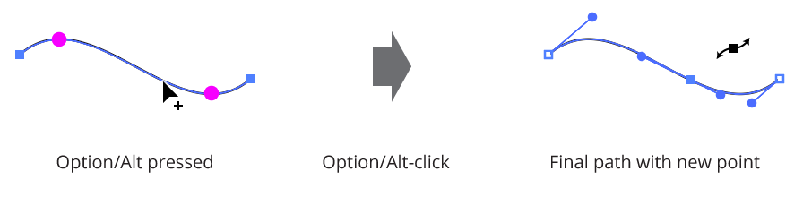
Add points with reposition point tool
Fast and Accurate Modes
By default, the tool operates in “Accurate” mode, which keeps the path’s geometry as close as possible to the original while allowing for the new point position(s). For smoother drag action (but somewhat more inaccurate results), the A key may be pressed to switch to “fast” mode.
Illustrator Location:
Illustrator Main Menu > Effect > AG Utilities > ...
Point Removal is an Astute Graphics live effect that removes anchor points from the paths in the artwork to which it is applied, based on criteria such as their distance from the previous point, the change in path angle at the point, or index. In contrast to the Smart Remove Points live effect, the handles of non-removed points are not adjusted to try to maintain path geometry.
As with most live effects, Point Removal appears in the main menu, under Effect > AG Utilities. It can also be applied directly from the Appearance panel using the “Add New Effect” button at the bottom of the panel.
Point Removal Parameters Dialog
After applying the live effect using the menu item (or when clicking on the existing effect in the Appearance panel to edit it), the parameters dialog will appear:

Point Removal Parameters Dialog
1. Criteria Popup
By default, points will be removed only if they match all of the enabled options (the first four checkboxes below). However you can change this to When They Match Any Enabled Options, Unless They Match All Enabled Options, or Unless They Match Any Enabled Options.
2. Distance From Previous
Points match when their distance (measured along the path) to the previous anchor point is between the minimum and the maximum values specified. The first point on an open path will never be matched.
3. Change In Path Angle
Points match when the change in the tangent angle of the path at the point is between the minimum and maximum values specified. Smooth points (unless malformed) will always have a 0° change in angle. The endpoints of an open path will never be matched.
4. Handles
Points match when their number of handles match the specified value: None, Any, Exactly One, or Exactly Two.
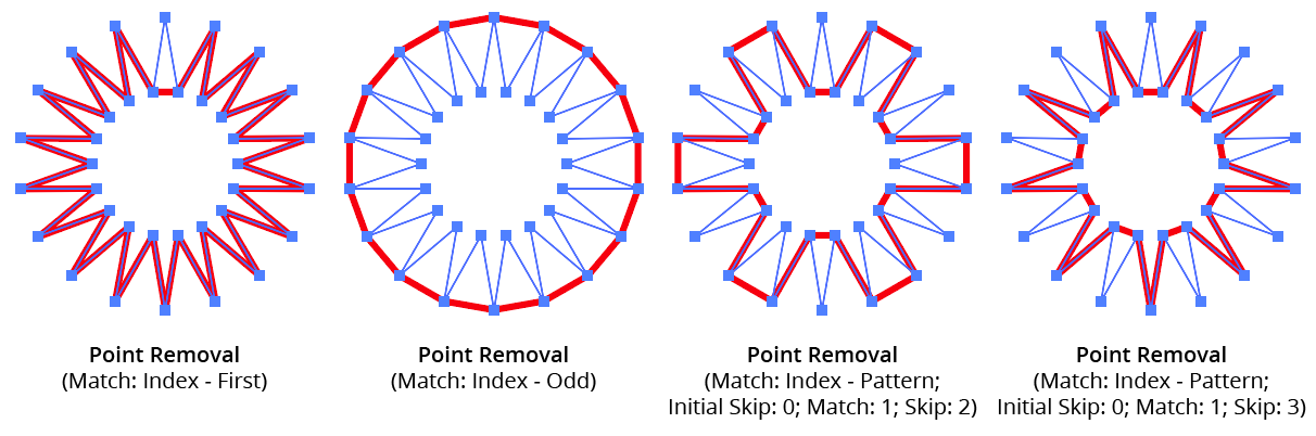
5. Index
Points match if their index matches the specified indices. Points are assigned indices starting at zero, increasing in the order in which they are encountered within the live effect. The default type of index match is Odd, i.e. 1, 3, 5, 7, etc. Other options are First, Last, First or Last, Even, and Pattern. Pattern type creates a repeating pattern of matching indices based on the three subsequent parameters.
6. Initial Skip
For Pattern index matching, the initial number of indices to skip over.
7. Match
For Pattern index matching, the number of indices to match after skipping some.
8. Skip
For Pattern index matching, the number of indices to skip over after matching some.
AG Utilities Live Effects - Point Removal Pattern
9. Randomize
Allows randomization of the removal.
10. Seed
Each random seed number leads to a different sequence of random values. Clicking the button picks a new seed, thereby changing the look of the artwork. To view or specify the seed number directly, Option/Alt-click the button. This lets you recreate a previously-generated look.
11. Retention Probability
The probability that a point that would normally be removed under the previous criteria will instead be retained.
12. Keep Same Geometry Paths Together
When the Point Removal effect is positioned under an artwork’s strokes and fills in the Appearance panel, the stroked and filled paths are passed to it separately, and their points would therefore normally be randomly affected independently, leading to some paths having different points removed when Randomize is enabled. Sometimes this can be solved by simply moving the Point Removal effect above them in the Appearance panel, but depending on the other effects that are present, this may not always be possible. In that case, enabling this setting allows paths with the exact same underlying geometry (such as fills and strokes of the same path) have the same points removed or retained.
13. Preview
As with all live effects, when enabled, changing a parameter will immediately update the artwork while the dialog is still open.
14. Help Button
Opens the help documentation in the Astute Manager. If this does not automatically appear, please ensure your Astute Manager is running first.
Illustrator Location:
Illustrator Main Menu > Effect > AG Utilities > ...
Smart Remove Points is an Astute Graphics live effect that removes anchor points from a path (like the Point Removal effect) but while trying to maintain the geometry of the path. This is achieved by adjusting the lengths (but not angles) of the handles on either side of the removed points.
As with most live effects, Smart Remove Points appears in the main menu, under Effect > AG Utilities. It can also be applied directly from the Appearance panel using the “Add New Effect” button at the bottom of the panel.
Smart Remove Points Parameters Dialog
After applying the live effect using the menu item (or when clicking on the existing effect in the Appearance panel to edit it), the parameters dialog will appear:

Smart Remove Points Parameters Dialog
1. Tolerance
Specifies how much the geometry of the path can change when removing a point. The value can range between 0 and 200, with a default of 10. Low values remove fewer points (prioritizing the path’s geometry) while high values remove more points (at the likely cost of some distortion).
2. Protect Sharp Corners
When enabled, corner points along the path where the path angle changes by more than 6° are never removed, regardless of the tolerance setting. This allows simplifying smooth sections of a path by using a large tolerance without having to worry that sharp corners will be lost.
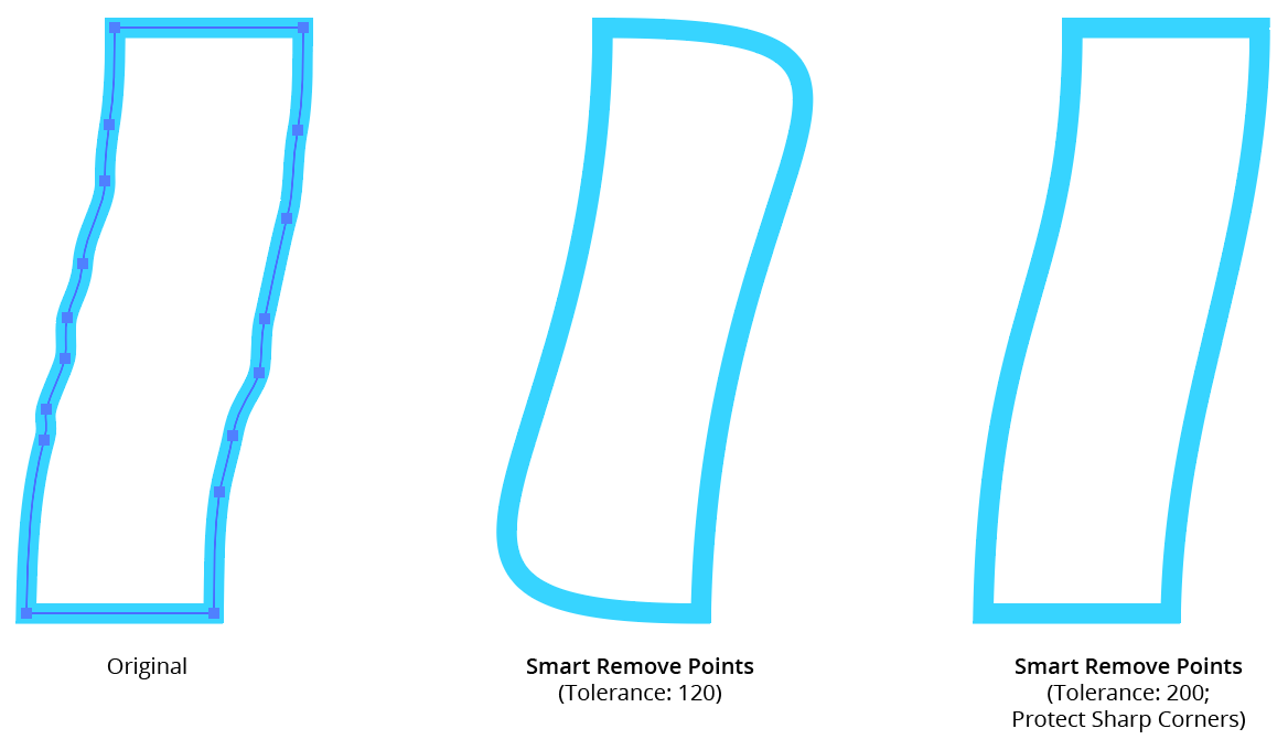
AG Utilities Live Effects - Smart Remove Points Example
3. Preview
As with all live effects, when enabled, changing a parameter will immediately update the artwork while the dialog is still open.
4. Help Button
Opens the help documentation in the Astute Manager. If this does not automatically appear, please ensure your Astute Manager is running first.