Rotation
 Randomini Tool
 Randomino Panel
 Rotate at Collision Tool
 Rotate to Collision Tool
 Orient Tool
 Quick Orient Tool
 Orient Transform Tool
![]() AG Transform Live Effect
AG Transform Live Effect
Illustrator Location:
Advanced Toolbar > Randomini Tool
When one or more art objects are selected and the Randomini tool is in use, its widget will appear, initially centered over the bounds of the selected art (it may later be repositioned; see below). By using the cursor to click or drag parts of the widget, the artwork can be edited. Except for Hue, all changes are previewed using outlines and are not actually applied to the art until the Apply button is clicked or the Enter key is pressed. Therefore, if you change your mind and decide not to randomize the art, simply switch to another tool and the art will remain as it was. All parameters are retained between uses of the tool. When not over a widget control, the cursor for the Randomini tool has the shape of a die showing various random faces. When nothing is selected, the Randomini tool can be dragged to marquee-select artwork.
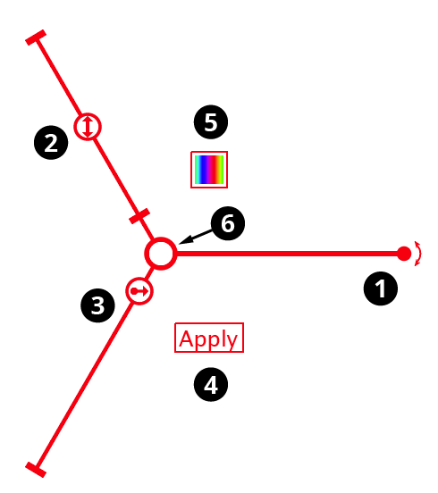
Randomino annotation widget
1. Rotation arm and control
Dragging the rotation control changes the angle up to which each piece of art will be randomly rotated around its bounding box center, in either a clockwise or counterclockwise direction. For example, setting the rotation arm at a 24° angle will cause the preview art to be rotated anywhere from -24° to 24°:
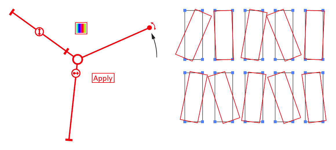
Randomino rotation arm preview
The rotation control may be double-clicked to set the rotation value numerically. Holding down the Shift key when dragging the control causes it to be constrained to steps of 10°. Holding down Command/Ctrl while dragging it enables “Slow-Drag,” which moves the control as if all cursor movements were reduced tenfold, allowing for fine-tuning.
2. Scale slider and thumb
Dragging the scale thumb changes the value up to which each piece of art will be randomly scaled from its bounding box center. For example, setting the scale value to 150% will cause the preview art to be scaled anywhere from 100% to 150%:
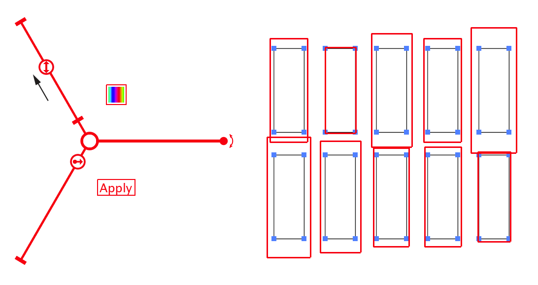
Randomini scaling control arm
The scale thumb may be double-clicked to set the scale value numerically. Holding down Shift while dragging the thumb causes the scale values to be constrained to integer values. Holding down Command/Ctrl enables “Slow-Drag”, as per the Rotation control.
3. Offset slider and thumb
Dragging the offset thumb changes the value up to which each piece of art will be randomly offset (shifted in position). For example, setting the offset value to 6pt will cause the preview art to be moved anywhere from 0 to 6 points. The offset direction is randomly chosen.
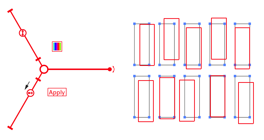
Randomini offset slider annotation
As with the scale thumb, the offset thumb may be doubleclicked to set the value numerically, Shift-dragged to constrain the value, or Command/Ctrl-dragged to enable “Slow-Drag.”
4. Apply button
Clicking the Apply button applies the currently displayed random rotation, scaling and offset to the selected art, as previewed. Immediately afterwards, since the art is still selected, new random parameters will be selected and previewed, allowing you to quickly apply multiple randomizations. To automatically deselect the art after applying the randomization, hold down Shift while clicking the Apply button. Pressing the Enter key has the same effect as clicking the Apply button unless no art is selected, in which case it opens the tool preferences dialog.
5. Hue button
Clicking the Hue button immediately randomizes the hues (strokes and fills) of the selected art. Note that black (which has zero brightness) and white (which has maximum brightness) are not affected by changing the hue. Also note that grouped objects are only affected if they have a stroke or fill applied in the Appearance panel at the group level, unless the “Ignore Grouping” preference is enabled (see Randomini: Preferences). Type objects are only affected if they have a stroke or fill applied in the Appearance panel above the Characters; to change the color of individual characters, use the Randomino panel.
6. Center control
The center control may be dragged to reposition the entire widget. Doubleclicking the center control resets all parameters to their default values (i.e., no rotation, no scaling, and no offset).
Illustrator Location:
Illustrator Main Menu > Window > Astute Graphics > Randomino
Rotates the selected artwork in a random way. Note that each rotation value is applied to the artwork in its current orientation; it does not set an absolute amount of rotation (as only certain objects in Illustrator have absolute rotations).
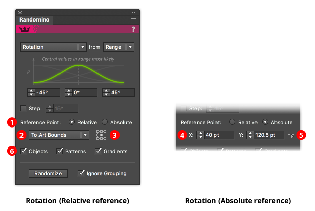
Randomino Panel Rotation Callouts
1. Reference point selector
Determines whether the reference point (the point about which the rotation will occur) is relative to the position of the art, or at an absolute position.
2. Relative reference point type
Selects what the reference point is relative to: the art’s bounds; the art’s first anchor point (for paths only); the art’s last anchor point (for paths only); or the artboard.
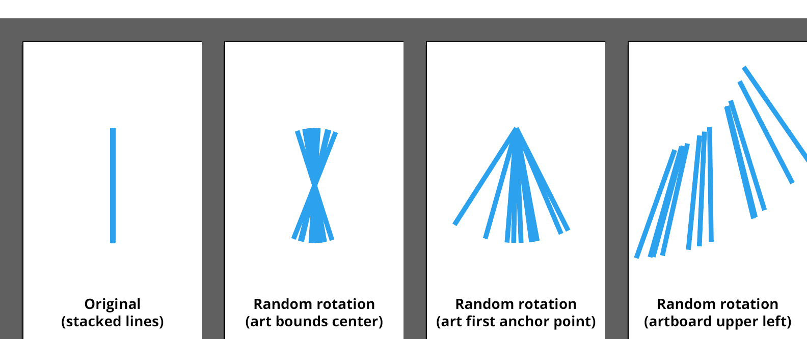
Randomino Rotated Lines
3. Relative reference point orientation
For Art Bounds and Artboard relative reference points, specifies the position of the reference point (top left, top, top right, middle left, etc).
4. Absolute reference point coordinates
The X and Y coordinates of the reference point.
5. Absolute reference point setter
Enables a tool that allows you to click at the reference point’s position.
6. Objects/Patterns/Gradients checkboxes
Rotation can be applied to only certain attributes of the selected art. You can choose to rotate the art objects themselves, any patterns found within the art, or any gradients found within the art.
Illustrator Location:
Advanced Toolbar > Selection Stack > Rotate at Collisions Tool
As the Rotate At Collision tool has several keypresses which can add or change its functionality, we strongly suggest installing the free Astute Graphics plugin Astute Buddy, which creates a panel that dynamically updates to inform you of the various keys which can be pressed in the tool’s current context.
Clicking
The Rotate At Collision tool can be used to click-select the two types of object that it operates on: paths and point text objects. Paths must be clicked at an anchor point or along a segment (not on their fills) and point text objects must be clicked on their baselines. In both cases the Rotate At Collision cursor will snap when hovering to eligible spots and display a red ring with informational text. Shift-clicking will deselect an already-selected object. Clicking on an empty area of the canvas will deselect everything.
Dragging
If the Rotate At Collision tool starts a drag from anywhere except over a path or point text object, it simply acts as a selection tool which creates a marquee for selecting objects. The tool preference Fully Select Groups and Compound Paths controls whether it acts like the Selection tool or the Direct Selection tool, and by holding down Option/Alt while dragging, you can temporarily invert the setting on the fly. To toggle the setting and affect future marquee operations as well, press the V key.
When the drag starts over a path or point text object, the object (and any other selected artwork) is dragged with the cursor, snapping when it “collides” with other paths on the artboard. The snap tolerance is 12 pixels by default but can be changed (see Rotate At Collision: Preferences). When a snap occurs, the dragged path or point text object, along with any other selected artwork, is rotated around the collision point in one of two ways. If an open path was dragged by one of its endpoints, then the path is rotated to be perpendicular (at the dragged endpoint) to the stationary path. Otherwise, the path or point text object is made tangent to the stationary path.
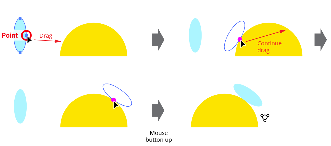
Rotate at Collisions Tool Path Example
When calculating the tangent angle of a path at a sharp corner point, the angle of the path going into the point and the angle of the path coming out of the point are averaged together, so a dragged path will be perpendicular to the imaginary line that bisects the angle:
Rotate at Collisions Tool Sharp Point Example
Because the tangent angle depends on path direction (clockwise vs. counter-clockwise), some paths may orient themselves on the opposite side from what is desired. In this case, pressing Space will toggle between the “normal” orientation and the alternate orientation:
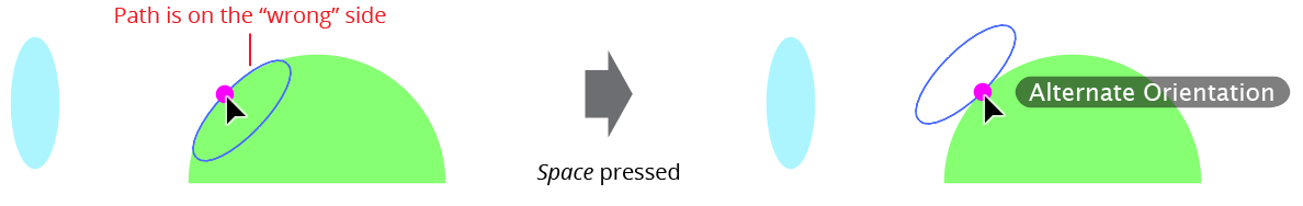
Rotate at Collisions Tool Alternate Orientation
Pressing one or more modifier keys while dragging artwork changes or adds tool functionality:
Shift: Constrains the motion of the dragged artwork to increments of 45° around the constrain angle.
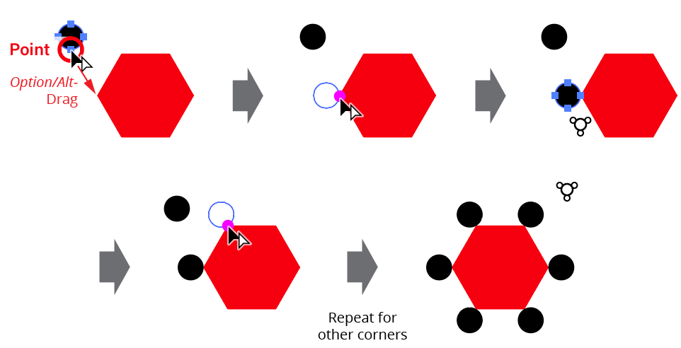
Option/Alt: Duplicates the dragged artwork instead of moving it.
Command/Ctrl: Overrides snapping to anchor points and straight midpoints along the stationary paths.
The following non-modifier keys can be pressed while dragging artwork to toggle or change various tool preferences on the fly (i.e., without having to go to the Rotate At Collision Preferences dialog):
Space: Toggles between normal orientation and alternate orientation (see above).
Up/Down Arrows: When the Use Collision Spacing preference is active, increases or decreases the spacing value by the native Keyboard Increment amount (see Rotate At Collision: Preferences).
A: Toggles the Add Points to Paths at Collisions preference.
L: Toggles the Snap To Locked Paths preference.
S: Toggles the Use Collision Spacing preference.
Illustrator Location:
Advanced Toolbar > Selection Stack > Rotate to Collisions Tool
As the Rotate To Collision tool has several keypresses which can add or change its functionality, we strongly suggest installing the free Astute Graphics plugin Astute Buddy, which creates a panel that dynamically updates to inform you of the various keys which can be pressed in the tool’s current context.
Clicking
Clicking with the Rotate To Collision tool relocates the rotation center point, indicated by a small red crosshair. This can be done whether or not artwork is selected (however, if artwork is not selected, then selecting it to actually rotate it may result in the rotation center point automatically moving if the preference Reset Rotation Center On New Selection is enabled (see Rotate To Collision: Preferences).
Doubleclicking
Doubleclicking on the rotation center point crosshair icon allows you to set its position numerically:
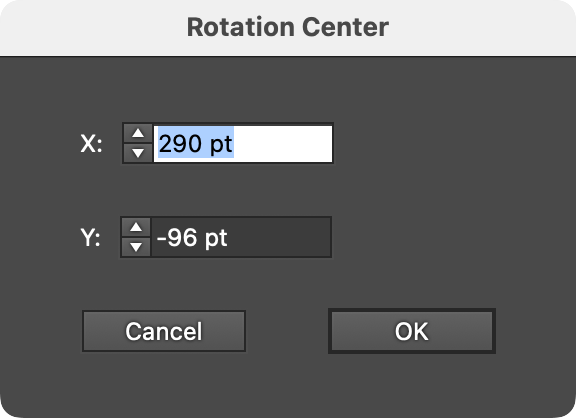
Rotate to Collisions Tool - Rotation Center Dialog
Dragging
If no artwork is selected, dragging with the Rotate To Collision tool simply relocates the rotation center point. Otherwise, all the selected art objects are rotated around the rotation center point in a manner similar to the native Rotation tool, except that they will snap to positions where paths in the selection “collide” with other paths, either at corner points or at places where the paths share a tangency. Small magenta dots will be drawn at spots where the tool has detected points of collision. The snap tolerance is 12 pixels by default but can be changed (see Rotate To Collision: Preferences).
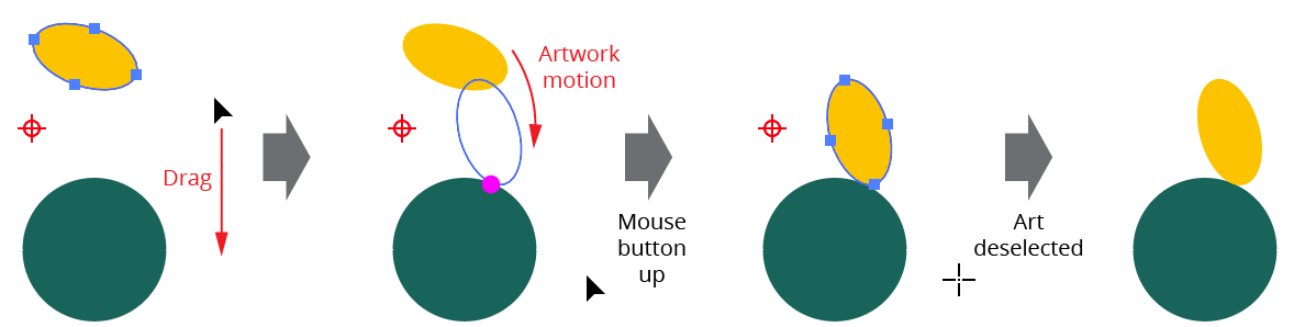
Rotate to Collisions Tool Example
Pressing one or more modifier keys while dragging artwork changes or adds tool functionality:
Shift: Constrains the rotation of the dragged artwork to increments of 45°. Since this takes precedence over the snapping behavior, it is provided for convenience only, since the same operation could be accomplished with the native Rotation tool.
Option/Alt: Duplicates the dragged artwork instead of moving it.
Command/Ctrl: Overrides collision snapping. This is provided for convenience only, since the same operation could be accomplished with the native Rotation tool.
The following non-modifier keys can be pressed while rotating artwork to toggle or change various tool preferences on the fly (i.e., without having to go to the Rotate To Collision Preferences dialog):
Up/Down Arrows: When the Use Collision Spacing preference is active, increases or decreases the spacing value by the native Keyboard Increment amount.
A: Toggles the Add Points to Paths at Collisions preference.
L: Toggles the Snap To Locked Paths preference.
S: Toggles the Use Collision Spacing preference.
X: Toggles the Snap To Pre-Drag Path Positions preference.
Illustrator Location:
Advanced Toolbar > Orient Tool
The Orient tool works by first drawing a reference line, and then rotating one end of the reference line to the desired angle; any selected artwork will be rotated by the same amount.
To create the reference line, either click once at the start point and once at the end, or click and drag in one step. Even when Smart Guides are turned off, the cursor will snap to anchor points, image corners, and the ends of text baselines with a snapping ring. The reference line shows a small circle (red in color, by default) at its start and end.
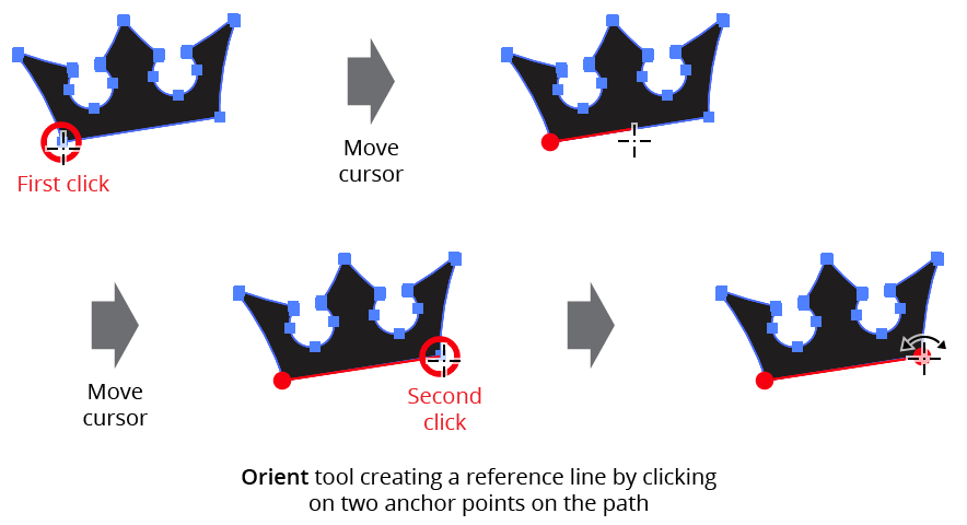
Orient Tool Setting Reference Line
After the reference line is set, clicking-and-dragging on either of its ends will rotate both the line and any selected art objects. By holding down Shift, the angle of the line can be constrained to 45° increments around the general constrain angle.
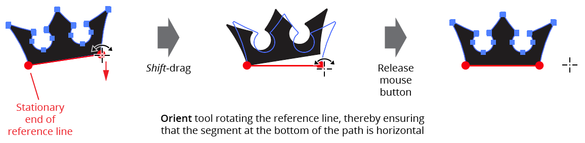
Orient Tool Rotating Art
Typically the reference line is made against the selected art, but this is not required. For example, to rotate selected horizontal artwork to be parallel to an angled straight path, one method would be to create the reference line horizontally starting from one end of the path and then (with Smart Guides enabled) rotate it until its endpoint snaps to the path.
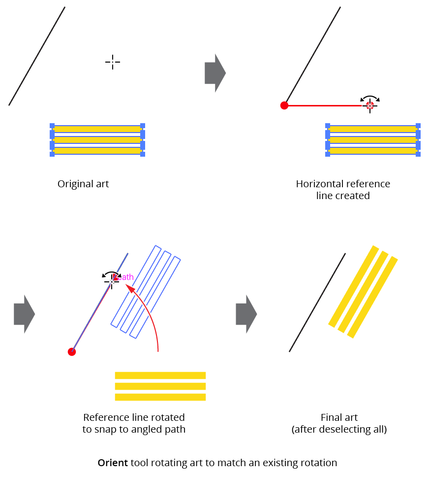
Orient Tool Rotating Art Example
If the Option/Alt key is pressed while the reference line is being rotated, the selected art will be duplicated into the new rotated position.
The reference line is retained until a new start point is clicked, or the Orient tool is deselected. Thus the selection can be changed without losing the current reference line position by temporarily switching to a selection tool by pressing Command/Ctrl.
Illustrator Location:
Advanced Toolbar > Orient Stack > Quick Orient Tool
The Quick Orient tool can be used in two ways: by simply clicking on art objects, or by drag-marqueeing over them. The artwork does not need to be selected. In either case, the default method for determining how much to rotate an object to “straighten” it is by looking at the rotation of the bounding box that Illustrator stores for each piece of art.
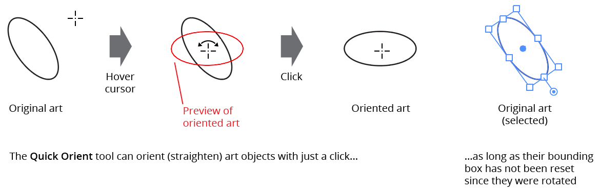
Quick Orient Tool Example
Therefore, if the art’s bounding box becomes reset (for example, by choosing Object > Transform > Reset Bounding Box), Quick Orient will not be able to automatically straighten the object except for certain types of art such as raster images, which keep rotation data in an additional location.
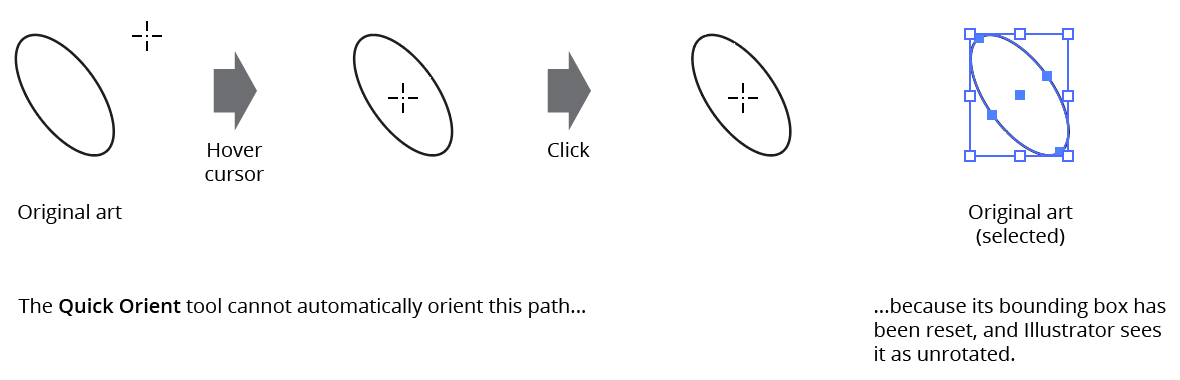
Quick Orient Rotated Bounding Box Example
However, for paths, Quick Orient can also use a path segment to rotate the path. To do this, hover the tool over a path segment and press the Option/Alt key. The path will be rotated such that the segment’s endpoints are horizontal (taking into account the general constrain angle), with the imaginary point halfway between the two endpoints acting as the center of rotation.
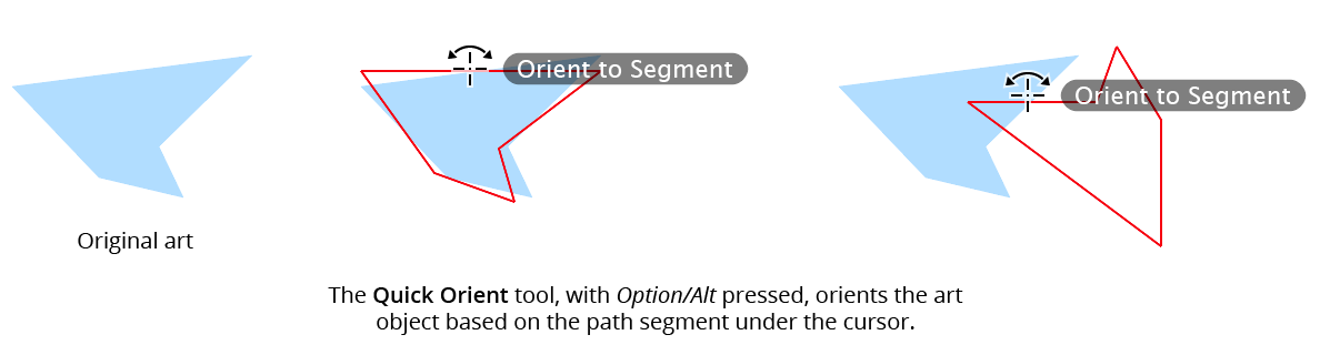
Quick Orient to Segment Example
Because the tool’s automatic orientation may not necessarily be the desired one, after clicking (and with the mouse button still down), the Space bar may be pressed to rotate the art repeatedly in 45° steps.
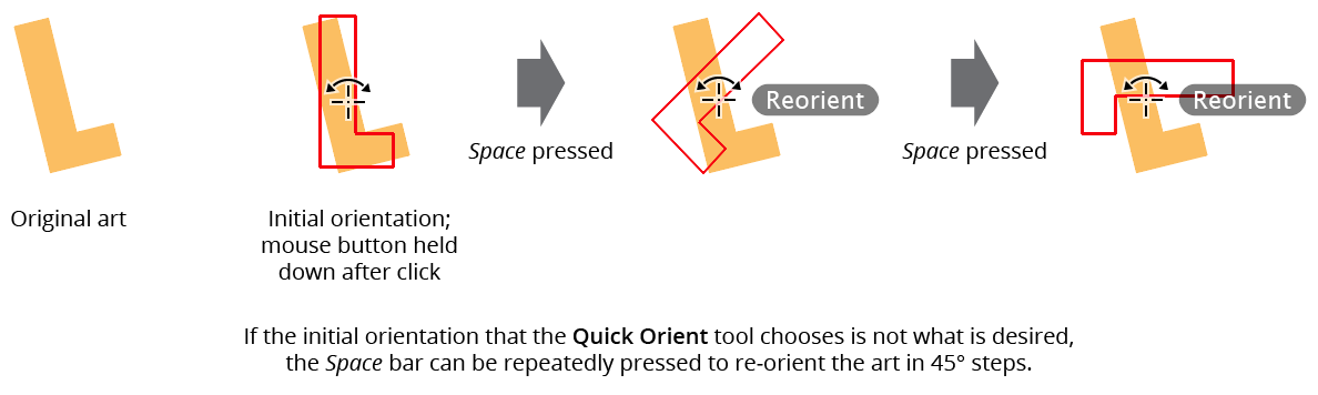
Quick Orient - Reorient Example
By default the Quick Orient tool acts on members of groups independently, but by holding Shift, all members of the top-most group to which the art under the cursor belongs (if any) will be rotated together.
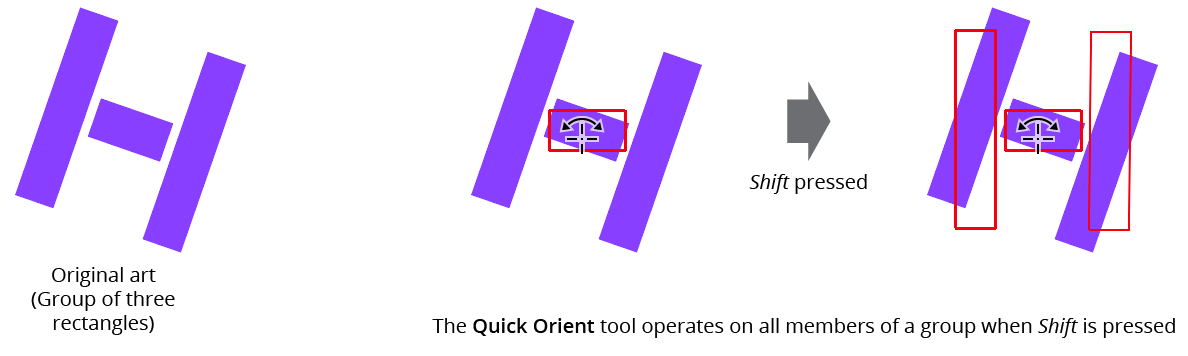
Quick Orient Whole Group Together
To orient multiple art objects in one step, drag a marquee over them:
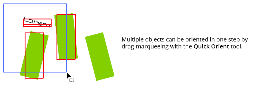
Quick Orient Marqueeing Example
The Quick Orient tool has no preferences. The color of the annotation used to preview the oriented artwork is taken from the Orient tool’s preference.
Illustrator Location:
Advanced Toolbar > Orient Stack > Orient Transform Tool
As the Orient Transform tool has several keypresses which can add or change its functionality, we suggest installing the free Astute Graphics plugin Astute Buddy, which creates a panel that dynamically updates to inform you of the various keys which can be pressed in the tool’s current context.
To use the Orient Transform tool, two reference lines must be drawn: a source line and a destination line. This can be done by using one of two methods: by clicking once on each endpoint, or by clicking and dragging. The former method has the advantage of allowing you to scroll, zoom, change the view mode, etc. in the middle of the operation. However, to use several shortcut keypresses (detailed below), you must continue to hold the mouse button down after the second click used to define the second reference line.
Reference lines are annotated with small circles (red, by default) at each end; the source line is solid while the destination line is dotted. The cursor will snap to anchor points, raster image corners, and the ends of point text baselines even when Smart Guides are turned off.
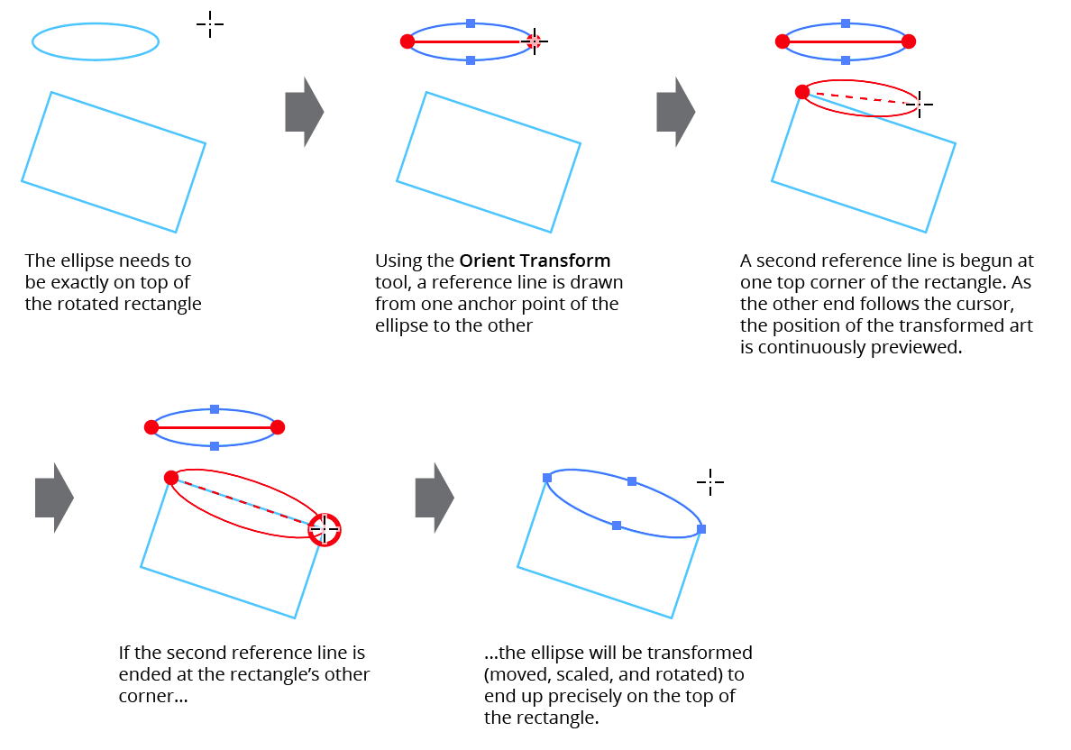
Orient Transform Tool Example
While the destination reference line is being drawn, all selected art objects will be previewed in red in the new position and size they would have after being linearly transformed such that the source reference line would be mapped onto the destination reference line. Releasing the mouse button after drawing the destination reference line finalizes the transformation. If Option/Alt is held down, the art is duplicated to its new position rather than being moved. Holding down the Shift key constrains either reference line to 45° increments around the general constrain angle.
If the destination reference line is being drawn by dragging, or if the mouse button is held down after the second click, several additional keypresses may be used to add or change functionality. As with all Astute tool keypresses, these will be indicated on the Astute Buddy panel.
Space: Flips the orientation of the transformed art, as if the destination reference line had been drawn in the opposite direction. This is faster than actually redrawing the line.
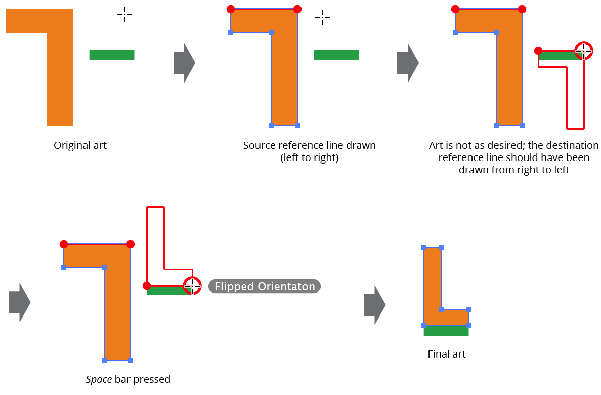
Orient Transform Flipped Orientation
A: Toggles mirroring. When mirroring is enabled, after being transformed, the artwork is additionally reflected across the destination reference line, which is drawn with a more widely-spaced dotted line.
Mirroring mode is retained across uses of the tool.
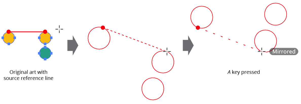
Orient Transform Mirrored Orientation
D: Toggles persistent duplicate, so the
Option/Altkey does not need to be held down to duplicate art. This can be useful when using the tool to make many successive copies of an art object. The mode is retained across uses of the tool.R: Toggles “retain selection” mode. Normally, after duplication, the selection is switched to the new transformed duplicate (and the source reference line is moved to the position of the destination reference line). However, when retain selection mode is enabled, the original art remains selected and the source reference line remains in its original position. Retain selection mode is always disabled to start.
S: Toggles size locking mode. When the size is locked, only the position and angle of the selected artwork will be modified.
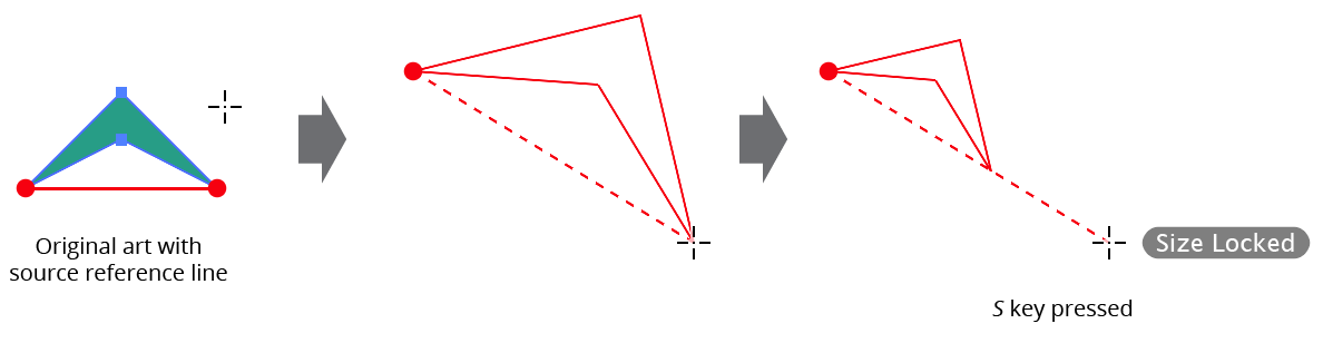
Orient Transform Size Locking
The Orient Transform tool honors the general preference Scale Stroke & Effects.
Illustrator Location:
The Rotate section of the dialog has the following controls:
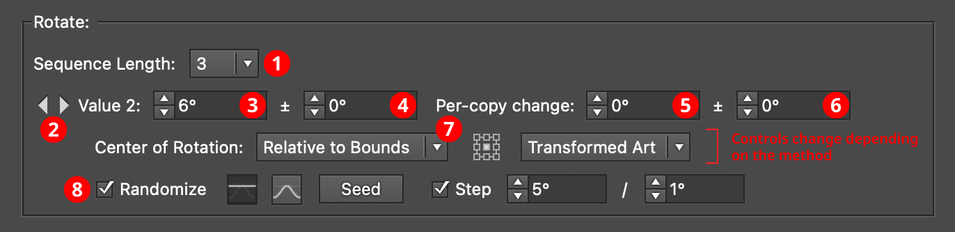
AG Transform Parameters Dialog, Rotate Section
1. Rotation Sequence Length
By default (and ignoring randomization), each copy receives the same rotation value (as with the native Transform effect). However, AG Transform offers sequences, which allow up to 8 different rotation values. If the number of copies exceeds the length of the sequence, the values simply repeat in a cycle. Each member of a sequence shares the same randomization parameters.
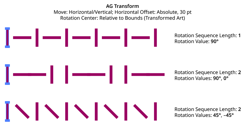
AG Transform Rotation Sequence Examples
2. Previous/Next Offset Buttons
Available when the sequence length is set to a value other than 1. Clicking either button will move between the sequence’s values, allowing any of them to be edited.
3. Value/Base Value
The angular value for the current sequence index. When randomization is enabled, this value specifies the base angle to which a random amount is added or subtracted.
4. Base Value Variation
Available when randomization is enabled; it is the maximum angular value which is added to or subtracted from the base value to get the random value. For example, if the base value is set to 45°, and the random variation is set to 10°, then angles from 35° to 55° may be produced.
5. Per-copy Change Value
The angular amount to add to the base value for each new copy. For example, if the base value is set to 20°, and the per-copy change is set to 3°, then the first copy will be rotated 20°, the second at 23°, the third at 26°, and so on.
6. Per-copy Change Value Variation
Available when randomization is enabled; it is the maximum angular amount which is added to or subtracted from the per-copy change value to get the random value.
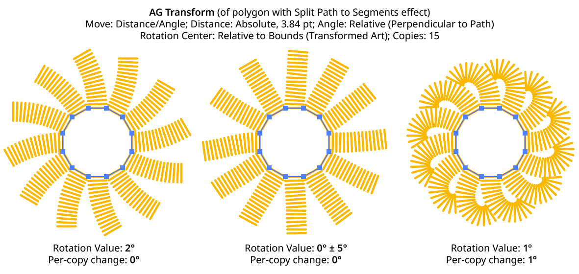
AG Transform Rotation Examples
7. Center of Rotation
The dropdown menu allows the choice between six different methods of specifying the center of rotation: Fixed, Relative to Bounds, Anchor Point, Position Along Path, Tagged Path, or Along Line.
Fixed: With this method, the center of rotation is simply specified by its coordinates.

AG Transform Center of Rotation Fixed Controls
This could be used to make multiple objects rotate around a common center, even if their position is subsequently adjusted:
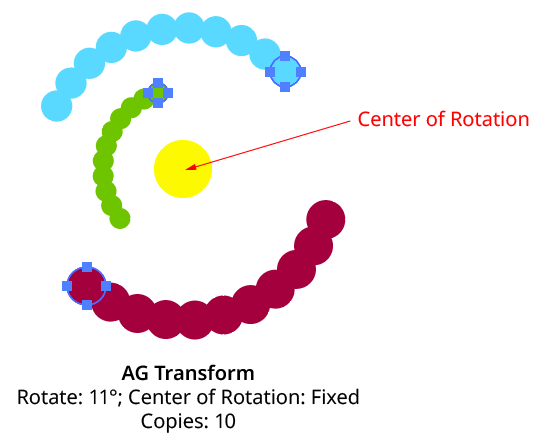
AG Transform Rotate Center Fixed
Relative to Bounds: This method (when used with Top-Level Art) is what the native Transform effect uses.

AG Transform Center of Rotation Relative to Bounds Controls
With this method, the center of rotation is located relative to the bounds of the specified art, using the standard nine-box control. The choices for the art type are Top-Level Art, Original Art, or Transformed Art. Top-Level Art is the art to which the AG Transform effect was applied (which may be a group). Original Art is the art at the specified Grouping Level which is being independently transformed, using its initial position for all copies. Transformed Art also refers to this art, but uses the transformed bounds for each copy, i.e., the center of rotation moves along with the copies.
To understand how changing the rotation center’s art type affects the results, it is helpful to understand the order of transform operations. For example, applying a native Transform effect with both a horizontal move and a rotation results in the left-hand image below and not the right-hand one — but why?
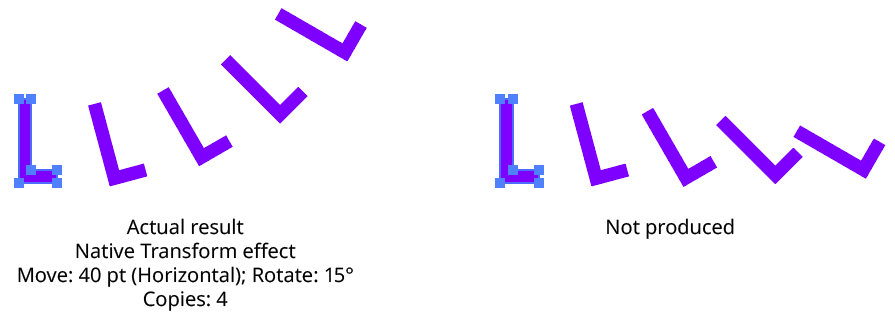
Native Transform Move Plus Rotate Example
The answer is due to two factors: the order of the transform operations, and the method of locating the center of rotation for each copy. For both the native Transform effect and AG Transform, each copy of the art is first scaled, then rotated, and finally moved (offset). The native Transform effect locates the center of rotation using the bounding box of the original art, and that center is used for all subsequent copies. Thus, the transform could be manually created as follows: Starting with the original art, a copy is made in place which is then rotated 15° around the center of rotation (the bounding box center). Then it is offset 40 pt to the right.
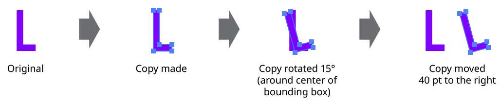
Native Transform Move Plus Rotate Manual Creation
This process is repeated for the second copy. Importantly, the center of rotation remains located at the center of the bounding box of the original art.
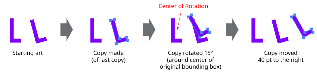
Native Transform Move Plus Rotate Manual Creation with Multiple Copies
The same steps are followed for each subsequent copy, which leads to the results shown originally.
AG Transform can be made to act like the native Transform effect for rotation by setting the Center of Rotation method to Relative to Bounds and the art type to Top-Level Art. However, the other two art types offer additional options:
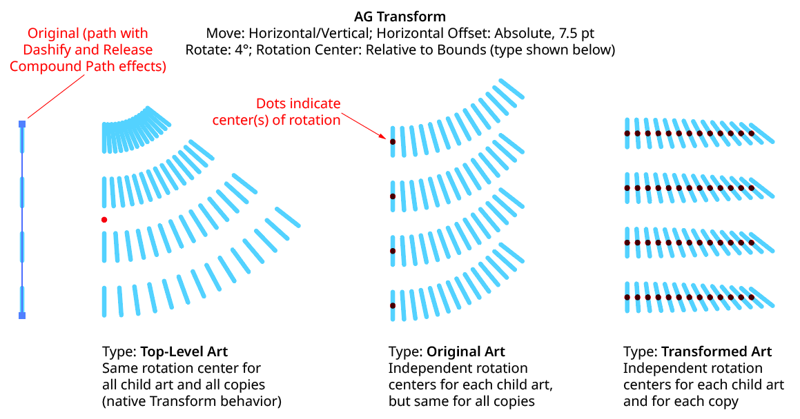
AG Transform Rotate Center Relative to Bounds Examples
Anchor Point: With this method, the center of rotation is located at the specified anchor point of the art at the specified grouping level. The rotation point is transformed for each copy, along with the art. If the art does not contain a path, the Relative to Bounds method will be used instead.

AG Transform Center of Rotation Anchor Point Controls
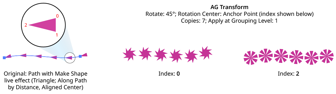
AG Transform Rotate Center Anchor Point Examples
Position Along Path: With this method, the center of rotation is located along the path of the art (from 0% to 100%) at the specified grouping level. The rotation point is transformed for each copy, along with the art. If the art does not contain a path, the Relative to Bounds method will be used instead.

AG Transform Center of Rotation Position Along Path Controls
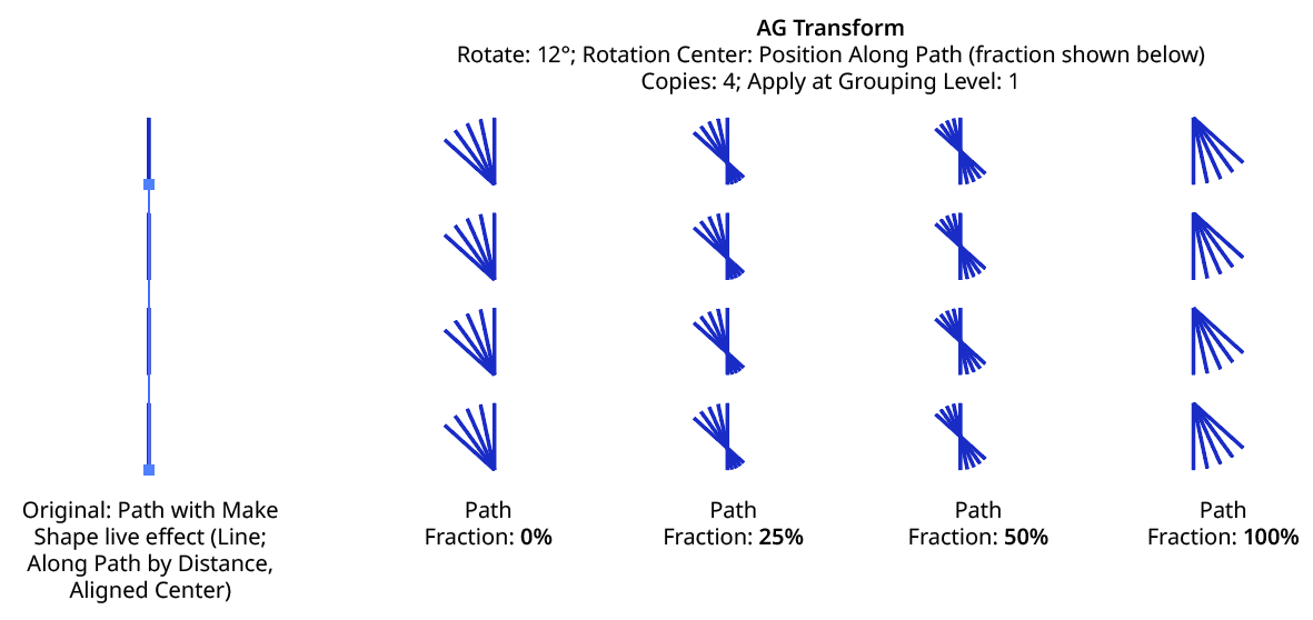
AG Transform Rotate Center Position Along Path Examples
Tagged Path: With this method, the center of rotation is located at the first anchor point of a path contained in the top-level group that has the note “AGTransformRotatePath” (as entered on the native Attributes panel). It is customary to use a single-point path for this purpose, so the path won’t inadvertently be made visible. If no such path exists, AG Transform uses the first path it finds in the top-level art. If no paths at all exist, the Relative to Bounds method will be used instead.
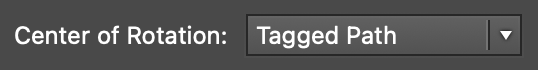
AG Transform Center of Rotation Tagged Path Controls
Along Line: With this method, the center of rotation is located along an imaginary line that passes through two points which are located using anchor point indices and t-values in the path art at the specified grouping level. The rotation point is transformed for each copy, along with the art. If the art does not contain a path, the Relative to Bounds method will be used instead.

AG Transform Rotate Center Along Line Controls
A. Start Index: The index of the anchor point used to locate the start of the imaginary line.
B. Start T-Val: The t-value (bezier-derived distance between the anchor point and the next anchor point, ranging from 0 to 1) of the start point.
C. End Index: The index of the anchor point used to locate the end of the imaginary line.
D. End T-Val: The t-value (bezier-derived distance between the anchor point and the next anchor point, ranging from 0 to 1) of the end point.
E. Fraction: The position of the center of rotation, as a fraction of the distance between the start point of the imaginary line and the end point. Values between 0% and 100% would put this point between the start and end, but the value can also be negative or greater than 100% to put the point outside this interval.
The Along Line method is similar to the Relative to Bounds method in that the center of rotation is always relative to the artwork. However, while Relative to Bounds only offers nine distinct positions, Along Line can specify an infinite number of such positions.
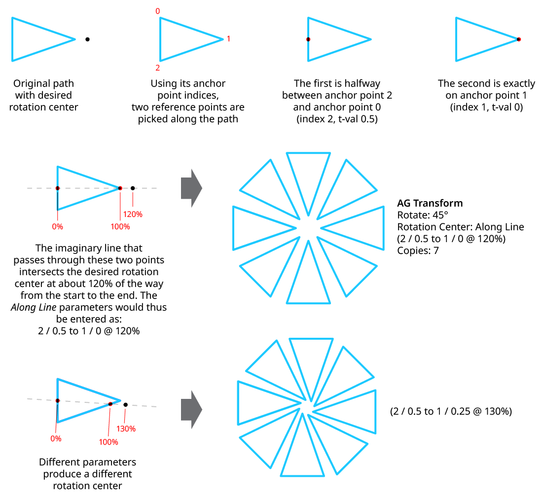
AG Transform Rotate Center Along Line Examples
8. Randomize
Randomization works the same way in the Rotate section of the dialog as it does in the Angle area of the Move section (when in Distance/Angle mode). Step values can be set for both the regular rotation value and for the per-copy change value.