 AG Utilities Live Effects
- Add Points Live Effect
- AG Array Live Effect
- AG Shear Live Effect
- AG Transform Live Effect
- Angle Cap Live Effect
- Close Path Live Effect
- Convert to Smooth Live Effect
- Dashify Live Effect
- Extend Path Live Effect
- Make Compound Path Live Effect
- Make Shape Live Effect
- Path Removal Live Effect
- Path Visualizer Live Effect
- Point Removal Live Effect
- Release Compound Path Live Effect
- Retract Handles Live Effect
- Reverse Path Direction Live Effect
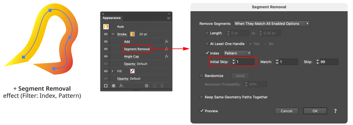
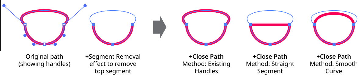
- Segment Removal Live Effect
- Smart Remove Points Live Effect
- Split Path to Segments Live Effect
- Stroke Attributes Live Effect
AG Utilities are a collection of Live Effects that live within the VectorScribe Plugin, and are often known as the Building Block Live Effects. They can be found under the menu item Effect > AG Utilities > ...
Add Points Live Effect
Add Points is an Astute Graphics live effect for paths that adds anchor points to paths, similar to the functionality of the “Add Points” function of the PathScribe panel. By itself, adding points is not particularly useful, as the look of the art won’t change; the real power comes by stacking the live effect with other live effects that operate on or depend on anchor point placement.
As with most live effects, Add Points appears in the main menu, under Effect > AG Utilities. It can also be applied directly from the Appearance panel using the “Add New Effect” button at the bottom of the panel.
Add Points Parameters Dialog
After applying the live effect using the menu item (or when clicking on the existing effect in the Appearance panel to edit it), the parameters dialog will appear:
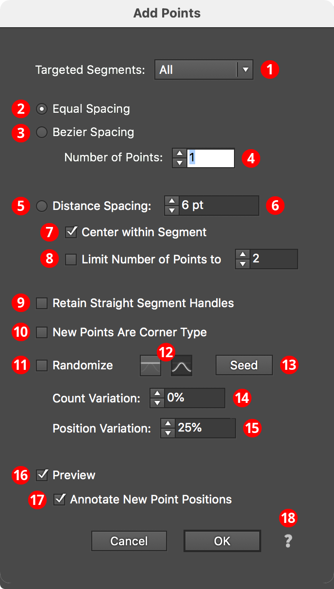
Add Points Parameters Dialog
1. Targeted Segments
By default, all segments in the path have points added to them, but this can be changed to First, Last, Even Only, Odd Only, Curved Only, or Straight Only segments. Even and odd refer to the index number of the segment, which starts at zero for the first segment in the path.
2. Equal Spacing Mode
In this mode, points are added such that the space between them (as measured along the path) is equal.
3. Bezier Spacing Mode
In this mode, points are added such that the cubic bezier t parameter is equally spaced. Generally, this adds more points to areas along the segment which are more tightly curved.
4. Number of Points
For Equal Spacing and Bezier Spacing modes, specifies the number of points to add along each segment.
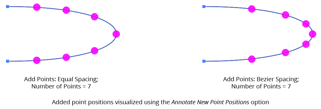
AG Utilities Live Effects - Add Points Equal or Bezier Spacing
5. Distance Spacing Mode
In this mode, points are added equally spaced along the path with the distance specified, adding as many as will fit along the segment unless Limit Number of Points is also enabled.
6. Distance Value
The distance between the added points when using Distance Spacing mode. If the distance value is greater than the segment’s length, no points will be added to the segment.
7. Center Within Segment
In Distance Spacing mode, causes the added points to be centered within the segment, so the distances from the segment’s ends to the first or last added point will be equal (but may not match the specified distance).
8. Limit Number of Points
In Distance Spacing mode, specifies the maximum number of points to add along each segment.
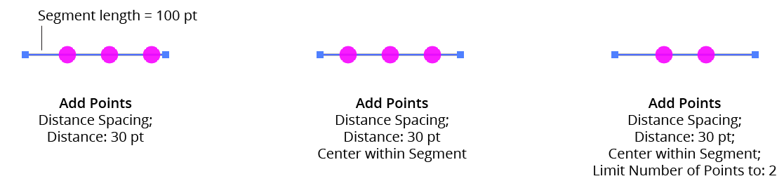
AG Utilities Live Effects - Add Points Distance Spacing
9. Retain Straight Segment Handles
Normally, when anchor points are added to a handleless straight segment, the new points have their handles removed. However, enabling this setting causes the handles to be retained, which can be useful when the new anchor points are subsequently moved and a smooth curve is desired.
10. New Points Are Corner Type
Forces the added points to have corner type rather than smooth. This does not change any handles that the point might have, only the point type.
11. Randomize
Allows for random variation in the count and/or position of the new points.
12. Distribution Curves
Specifies either a linear distribution in random values (all values in the range are equally likely to be chosen) or a Gaussian distribution (central values in the range are more likely to be chosen).
13. Seed
Each random seed number leads to a different sequence of random values. Clicking the button picks a new seed, thereby changing the look of the artwork. To view or specify the seed number directly, Option/Alt-click the button. This lets you recreate a previously-generated look.
14. Count Variation
Specifies the random variation in the added point count (valid for Equal Spacing and Bezier Spacing modes only). For example, if the count is set to 20, then a variation value of 25% would produce count values that vary by as much as 20 × 25% = 5, that is, between 16 and 20; a variation value of 100% would produce count values between 1 and 20.
15. Position Variation
Specifies the random variation in the final positions of the added points.
16. Preview
As with all live effects, when enabled, changing a parameter will immediately update the artwork while the dialog is still open.
17. Annotate New Point Positions
When enabled, the positions of the added points will be temporarily displayed using magenta dot annotations, which is useful if subsequent live effects have not been added to the artwork yet, because by itself, Add Points will produce no visual change to the art.
18. Help Button
Opens the help documentation in the Astute Manager. If this does not automatically appear, please ensure your Astute Manager is running first.
AG Array Live Effect
AG Array is an Astute Graphics live effect for creating arrays, or grids, of artwork. It includes multiple methods of specifying the horizontal and vertical sizes, and can stagger the items as well as switch their stacking order.
As with most live effects, AG Array appears in the main menu, under Effect > AG Utilities. It can also be applied directly from the Appearance panel using the “Add New Effect” button at the bottom of the panel.
AG Array Parameters Dialog
After applying the live effect using the menu item (or when clicking on the existing effect in the Appearance panel to edit it), the parameters dialog will appear:
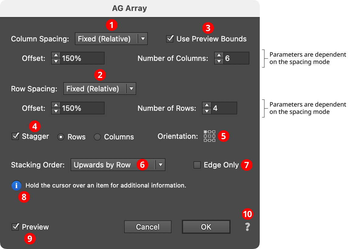
AG Array Parameters Dialog
1. Column Spacing Mode
The column spacing of the array can be specified in one of four ways:
a. Fixed (Absolute): The horizontal offset between columns is specified as an absolute value (for example, 72 pt). If this value is smaller than the width of the art object, the columns will overlap. The number of columns is also specified, from 1 to 1000.
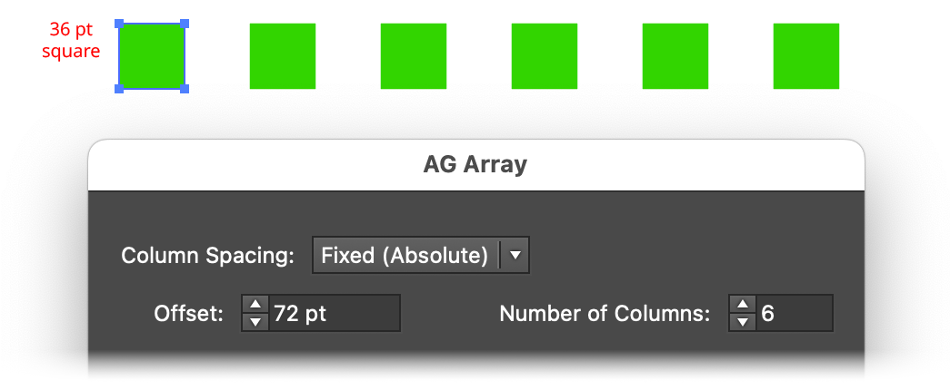
AG Array Spacing - Fixed (Absolute) Mode
b. Fixed (Relative): The offset between columns is specified as a percentage value relative to the width of the bounding box of the art (for example, 150%). If this value is less than 100%, the columns will overlap. As with Fixed (Absolute), the number of columns is also specified, from 1 to 1000.
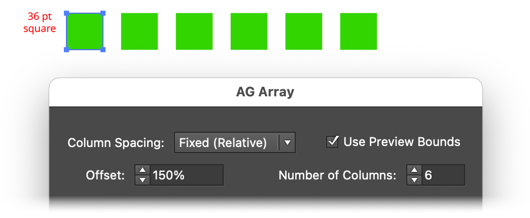
AG Array Spacing - Fixed (Relative) Mode
c. Total Dimension: The overall width of the array is specified. If this value is equal to or smaller than the width of the art object, then all of the columns will be stacked atop each other. Otherwise AG Array adjusts the offset so the specified number of columns is evenly spaced across the width.
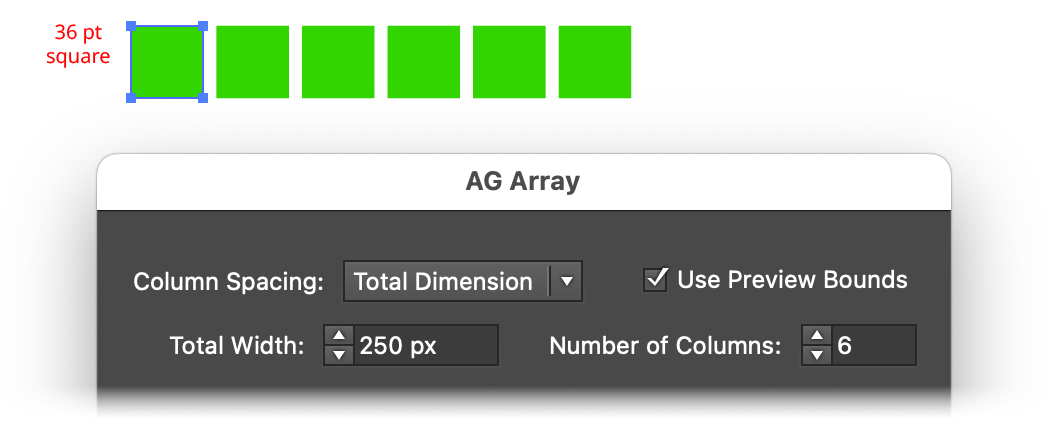
AG Array Spacing - Total Dimension Mode
d. Fill: As with Total Dimension mode, the final width of the array is specified. AG Array then creates as many columns as will fit in this width while keeping the gutter between columns equal to or greater than the Minimum Gutter value.
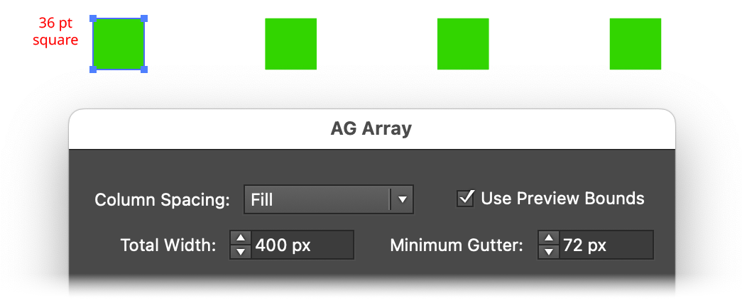
AG Array Spacing - Fill Mode
2. Row Spacing Mode
The row spacing of the array can be specified in one of four ways:
a. Fixed (Absolute): The vertical offset between rows is specified as an absolute value (for example, 72 pt). If this value is smaller than the height of the art object, the rows will overlap. The number of rows is also specified, from 1 to 1000.
b. Fixed (Relative): The offset between rows is specified as a percentage value relative to the height of the bounding box of the art (for example, 150%). If this value is less than 100%, the rows will overlap. As with Fixed (Absolute), the number of rows is also specified, from 1 to 1000.
c. Total Dimension: The overall height of the array is specified. If this value is equal to or smaller than the height of the art object, then all of the rows will be stacked atop each other. Otherwise AG Array adjusts the offset so the specified number of rows is evenly spaced across the height.
d. Fill: As with Total Dimension mode, the final height of the array is specified. AG Array then creates as many rows as will fit in this height while keeping the gutter between rows equal to or greater than the Minimum Gutter value.
3. Use Preview Bounds
Overrides the general preference of the same name. When enabled, the strokes and live effects of the artwork are included in its bounding box, which affects column or row positioning unless the spacing mode is set to Fixed (Absolute).
AG Array Use Preview Bounds
4. Stagger
When enabled, alternate rows (or columns) are shortened by one item and shifted so their items fall halfway between those of the previous row or column.
AG Array Stagger
5. Orientation
Specifies the orientation of the entire array in relation to the bounding box of the original art. The default is to have the upper left corner of the array in the same location as the upper left corner of the original art.
AG Array Orientation
6. Stacking Order
Specifies how the items in the array are stacked: Upwards by Row, Upwards by Column, Downwards by Row, or Downwards by Column, where row items are created from left to right and column items are created from top to bottom.
AG Array Stacking Order
7. Edge Only
When enabled, only the first and last columns and rows of the array will be populated.
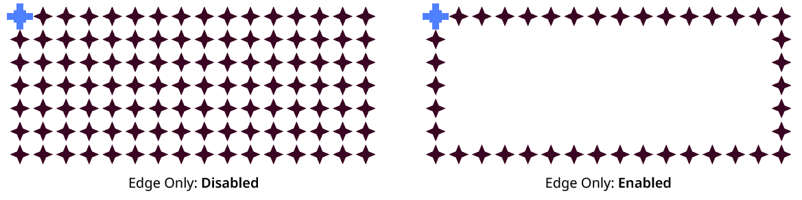
AG Array Edge Only
8. Informational area
Shows a brief description of each control when the cursor is being hovered over it.
9. Preview
As with all live effects, when enabled, changing a parameter will immediately update the artwork while the dialog is still open.
10. Help Button
Opens the help documentation in the Astute Manager. If this does not automatically appear, please ensure your Astute Manager is running first.
AG Shear Live Effect
AG Shear is an Astute Graphics live effect that adds the ability to shear art objects, including live text, non-destructively — without resorting to hard-to-edit, multiple-stacked native Transform effects.
As with most live effects, AG Shear appears in the main menu, under Effect > AG Utilities. It can also be applied directly from the Appearance panel using the “Add New Effect” button at the bottom of the panel.
AG Shear Parameters Dialog
After applying the live effect using the menu item (or when clicking on the existing effect in the Appearance panel to edit it), the parameters dialog will appear:
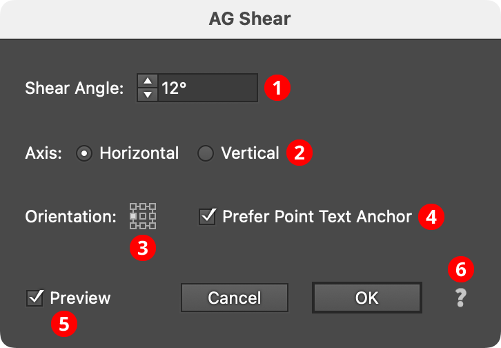
AG Shear Parameters Dialog
1. Shear Angle
The angle of the shear, from –85° to 85°. As with the native Shear tool, positive shear angles slant the artwork to the right (when the axis is set to horizontal) or downwards (when the axis is set to vertical).
2. Axis
The axis along which to shear, either Horizontal or Vertical. Axes of an arbitrary angle, which are rarely used, are not supported.
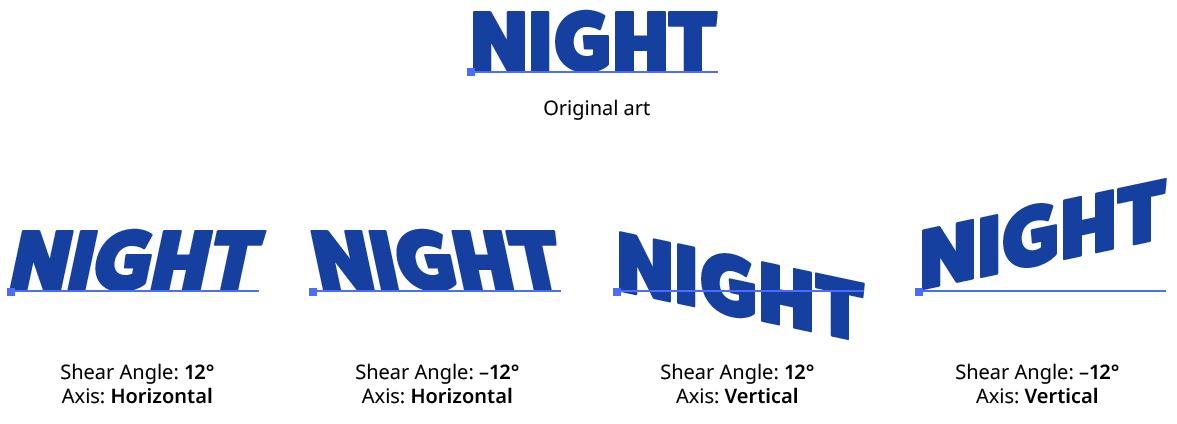
AG Shear Examples
3. Orientation
The position of the shear’s transformation point in relation to the artwork’s bounding box.
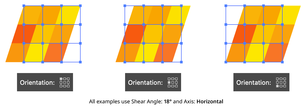
AG Shear Orientation
4. Prefer Anchor Point Text
When enabled, and the art object is a single point text object, then the shear’s transformation point will always be placed at the anchor point of the text object, regardless of the Orientation setting. This ensures that the baseline of the text passes through the anchor point of the text, as normal.
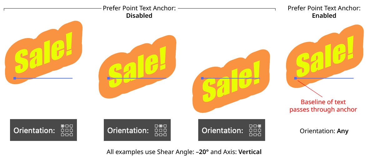
AG Shear Prefer Point Text Anchor
5. Preview
As with all live effects, when enabled, changing a parameter will immediately update the artwork while the dialog is still open.
6. Help Button
Opens the help documentation in the Astute Manager. If this does not automatically appear, please ensure your Astute Manager is running first.
AG Transform Live Effect
AG Transform is a powerful Astute Graphics live effect that greatly expands upon the native Transform effect by adding features such as the ability to affect different grouping levels of the art, the option to move by distance and angle instead of simply by X- and Y-coordinates, sequences with separate parameters, additional options for specifying the centers of scaling and rotation, the ability to change the stacking order, filtering for only affecting a subset of multiple objects, and more.
As with most live effects, AG Transform appears in the main menu, under Effect > AG Utilities. It can also be applied directly from the Appearance panel using the “Add New Effect” button at the bottom of the panel.
AG Transform Parameters Dialog
After applying the live effect using the menu item (or when clicking on the existing effect in the Appearance panel to edit it), the parameters dialog will appear. The dialog is large, and is described by section:
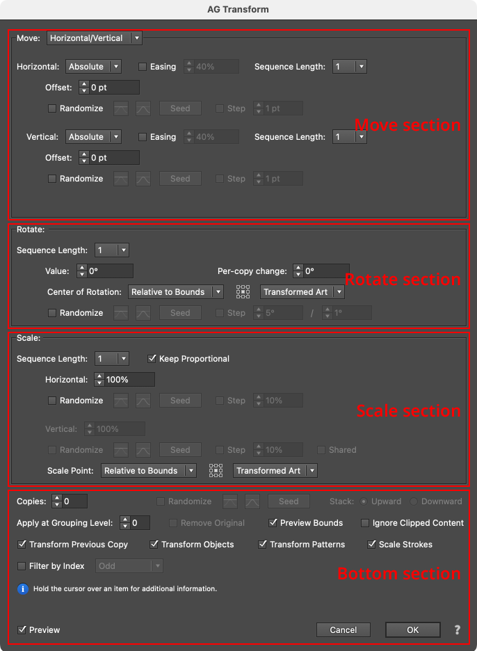
AG Transform Parameters Dialog Sections
Although the Move, Rotate and Scale sections are stacked in that order on the panel, the operations are actually performed in the reverse order. In other words, to transform the art, it is first scaled, then rotated, and finally moved. This is consistent with the native Transform effect’s order of operations.
Move Section: Horizontal/Vertical
Moving (offsetting) can be done in two main modes: Horizontal/Vertical (as with the native Transform, in which the offset is specified by its horizontal and vertical components) or Distance/Angle, in which the offset is specified by its distance and angle components. The main mode is controlled by a dropdown menu at the top of the Move section. In Horizontal/Vertical mode, the move section of the dialog has the following controls:
AG Transform Parameters Dialog: Move Section (Horizontal, Vertical)
1. Main Mode
The dropdown menu allows the choice between Horizontal/Vertical mode and Distance/Angle mode.
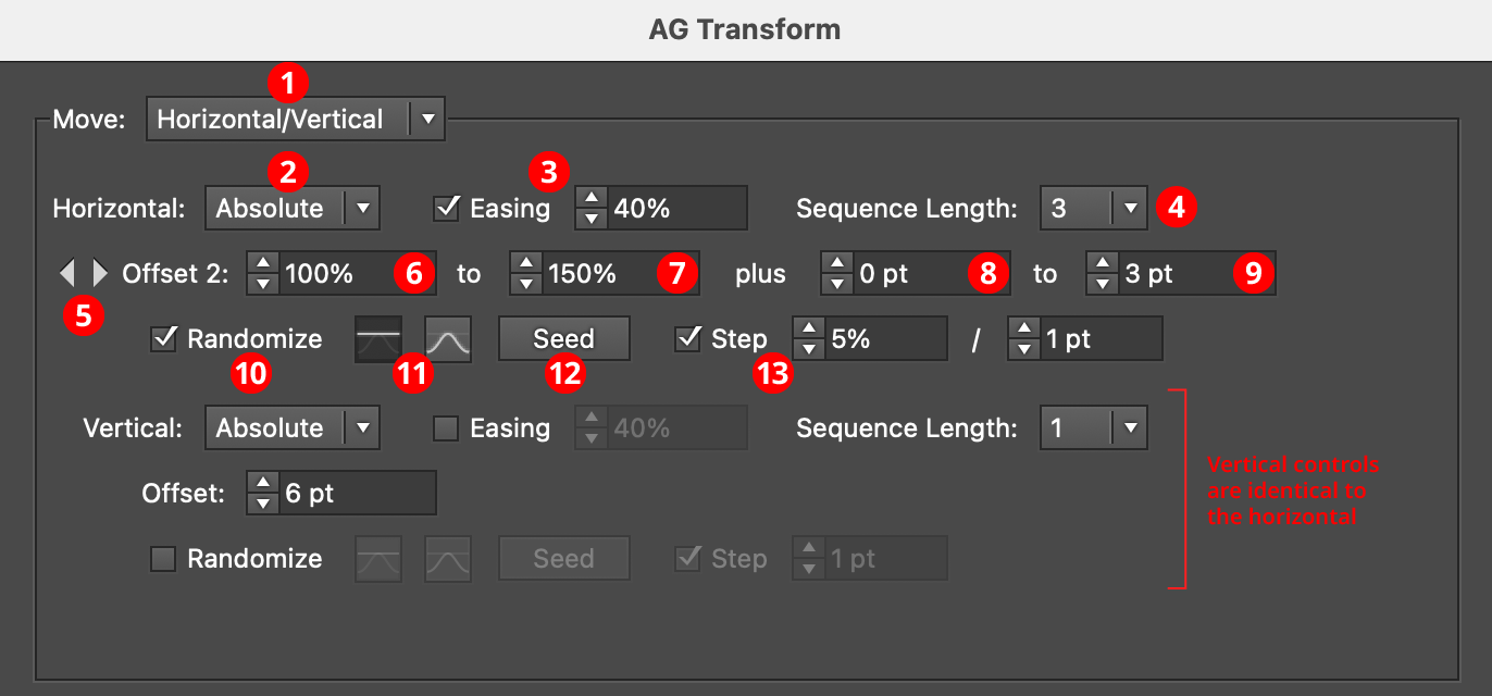
2. Horizontal/Vertical Submode
In Horizontal/Vertical mode, the dropdown menu allows the choice between Absolute or Relative submodes for both the horizontal and vertical components of the offset. In Absolute submode, each offset component is specified using an absolute value, such as 12 pt. In Relative submode, each offset component is specified using a percentage of the width (or height, for the vertical component) of the art’s bounding box, plus an optional non-relative value. Thus, when the submode is set to Relative and the offset is set to 100%, the “plus” value controls the gap between objects when multiple copies are made:
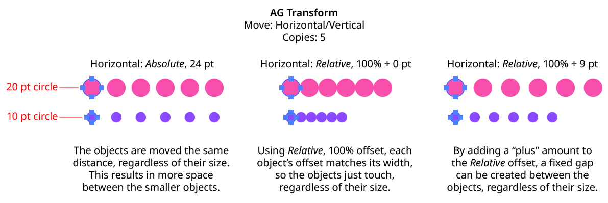
AG Transform Move Absolute Vs. Relative
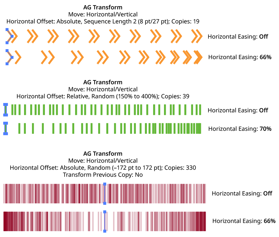
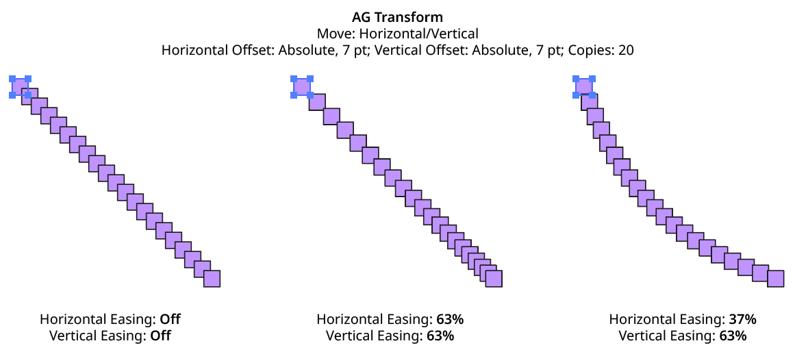
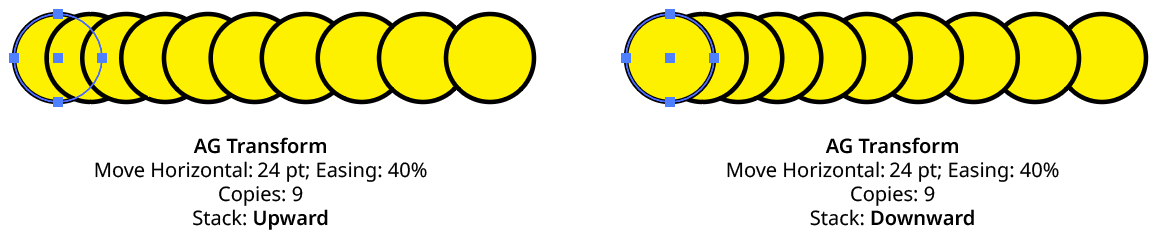
3. Horizontal/Vertical Easing
Easing controls the final spacing (either in the horizontal or vertical direction) of all of the transformed copies. When enabled, the easing value (from 1% to 99%) specifies where the middle copy should be placed (as a percentage of the distance from the original to the last copy). It therefore determines whether the copies increase their spacing as they get further away from the original (for values less than 50%), or decrease their spacing (for values more than 50%).
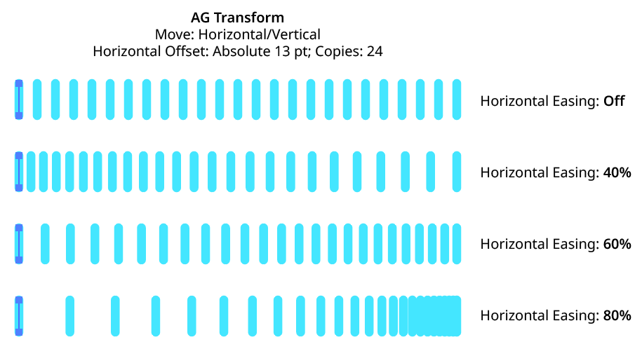
AG Transform Easing Examples 1
Easing can be used with both sequences and randomization. If the offsetting causes the copies to be created both to the left and right of the original, then the easing is done separately for each side.
AG Transform Easing Examples 2
Using a different easing value for the horizontal and vertical components of the offset causes the trail of copies to move in a curve:
AG Transform Easing Examples 3
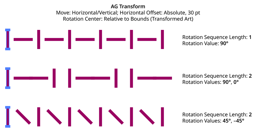
4. Horizontal/Vertical Sequence Length
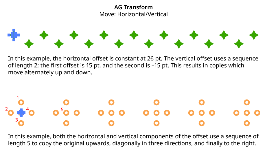
By default (and ignoring randomization), each copy receives the same offset (as with the native Transform effect). However, AG Transform offers sequences, which allow up to 8 different offsets. The horizontal component of the offset can have a different sequence length from the vertical. If the number of copies exceeds the length of the sequence, the values simply repeat in a cycle. Each member of a sequence shares the same randomization parameters.
AG Transform Horizontal Vertical Sequence Examples
5. Previous/Next Offset Buttons
Available when the sequence length is set to a value other than 1. Clicking either button will move between the sequence’s offsets, allowing any of them to be edited.
6. Offset/Minimum Offset
The horizontal (or vertical) offset for the current sequence index. In Absolute submode, this is an absolute value like 12 pt. In Relative submode, this is a percentage of the width (or height) of the bounding box of the art. When randomization is enabled, this value specifies the minimum offset that may be randomly produced.
7. Maximum Offset
Available when randomization is enabled; it specifies the maximum horizontal (or vertical) offset that may be randomly produced for the current sequence index.
8. “Plus” Offset/Minimum “Plus” Offset
Available when in Relative submode; it specifies an additional non-relative offset that is added to the relative offset for the current sequence index (and may be negative). When used with a relative offset of 100%, for example, this could be used to create fixed gaps of a specific size between copies, regardless of the size of the original art. When randomization is enabled, this value specifies the minimum “plus” offset that may be randomly produced.
9. Maximum “Plus” Offset
Available when in Relative submode and randomization is enabled; it specifies the maximum horizontal (or vertical) “plus” offset that may be randomly produced for the current sequence index.
10. Horizontal/Vertical Randomize
When randomization is enabled, the offset (or offsets, if using a sequence) are not fixed for each copy, but are chosen randomly between the specified minimum and maximum values. The distribution of those values (linearly or in a Gaussian manner) can be specified, as well as the random seed. All sequence indices share the same randomization parameters.
11. Distribution Curves
Specifies either a linear distribution in random values (all values in the range are equally likely to be chosen) or a Gaussian distribution (central values in the range are more likely to be chosen, also known as a “bell curve”).
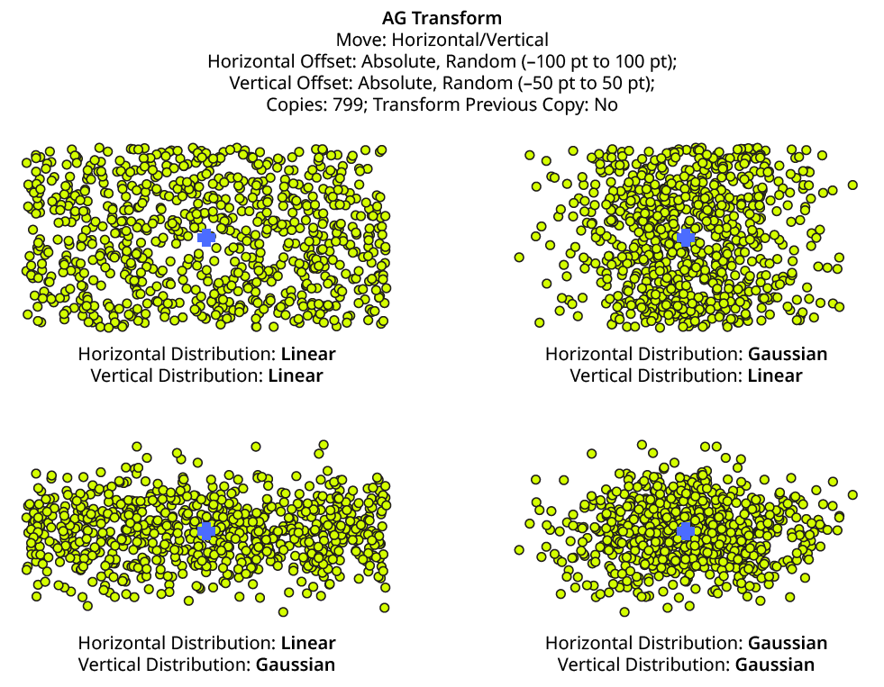
AG Transform Linear Vs. Gaussian Distribution
12. Seed
Each random seed number leads to a different sequence of random values. Clicking the button picks a new seed, thereby changing the look of the artwork. To view or specify the seed number directly, Option/Alt-click the button. This lets you recreate a previously-generated look. The horizontal and vertical components of the offset have independent seeds.
13. Step
Constrains each final offset value (after randomization) to multiples of the specified step value while still remaining in the original range (when possible). For example, if an absolute offset is set to a minimum of 12 pt and a maximum of 24 pt, then normally any value between those amounts might be produced — say, 17.448 pt. But enabling Step with a value of 5 pt would result in only values of 15 pt and 20 pt.
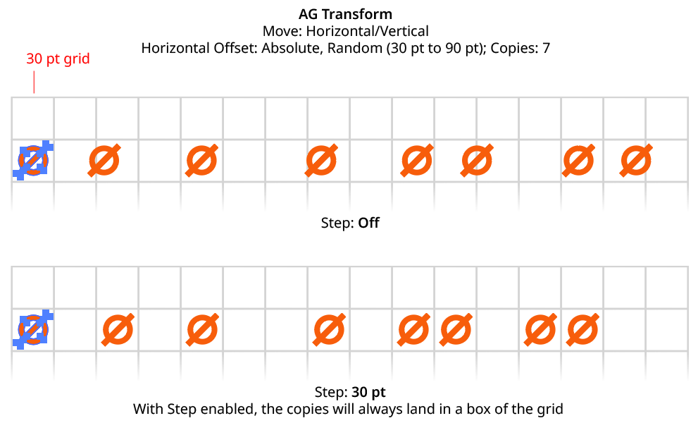
AG Transform Horizontal Offset with Step
When using Step with Relative offsets, two step values are available. The first value is the step value for the relative amount (a percentage), and the second is the step value for the absolute “plus” offset.
Move Section: Distance/Angle
In Distance/Angle mode, the Move section of the dialog has the following controls:
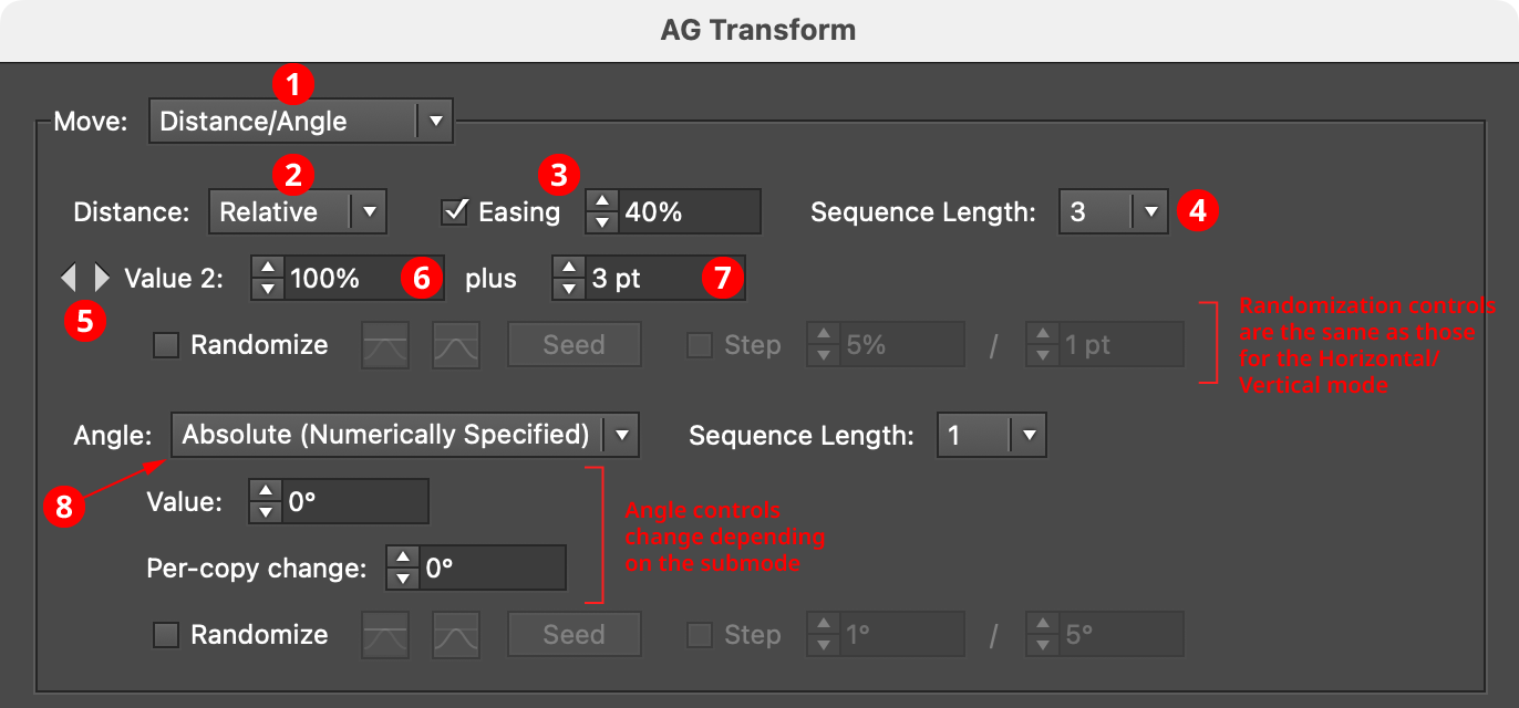
AG Transform Parameters Dialog, Move Section (Distance Angle)
1. Main Mode
The dropdown menu allows the choice between Distance/Angle mode and Horizontal/Vertical mode.
2. Absolute/Relative Submode
The dropdown menu allows the choice between Absolute or Relative submodes for the distance component of the offset. In Absolute submode, the offset is specified using an absolute value, such as 12 pt. In Relative submode, the value is specified using a percentage of the width of its bounding box, plus an additional non-relative value.
3. Distance Easing
Easing controls the final spacing of all of the transformed copies based on their distance from the original object. When enabled, the easing value (from 1% to 99%) specifies where the middle copy should be placed (as a percentage of the distance from the original to the last copy). It therefore determines whether the copies increase their spacing as they get further away from the original (for values less than 50%), or decrease their spacing (for values more than 50%).
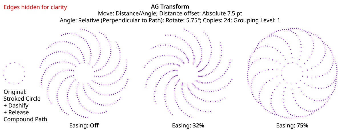
AG Transform Distance Easing
Distance easing can be used with both sequences and randomization.
4. Distance Sequence Length
See Horizontal/Vertical Sequence Length.
5. Previous/Next Value Buttons
Available when the sequence length is set to a value other than 1. Clicking either button will move between the sequence’s values, allowing any of them to be edited.
6. Offset/Minimum Value
The distance value for the current sequence index. In Absolute submode, this is an absolute value like 12 pt. In Relative submode, this is a percentage of the width of the bounding box of the original art. When randomization is enabled, this value specifies the minimum value that may be randomly produced.
7. Maximum Value
Available when randomization is enabled; it specifies the maximum value that may be randomly produced for the current sequence index.
8. Angle Submode
The dropdown menu allows the choice between Absolute (Numerically Specified), Relative (Start Point/End Point), or Relative (Perpendicular to Path) submodes for the angle component of the offset.
Absolute (Numerically Specified) submode: the angle is specified using an absolute value, such as 45°. In this submode, the angle controls are as follows:
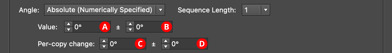
AG Transform Parameters Dialog, Angle Absolute Submode
A. Value/Base Value: The angle component of the offset for the current sequence index. When randomization is enabled, this value specifies the base angle to which a random amount is added or subtracted.
B. Base Value Variation: Available when randomization is enabled; it is the maximum angular amount which is added to or subtracted from the base value to get the random value. For example, if the base value is set to 45°, and the random variation is set to 10°, then angles from 35° to 55° may be produced.
C. Per-copy Change Value: The angular amount to add to the base value for each new copy. For example, if the base value is set to 20°, and the per-copy change is set to 3°, then the first copy will be offset at an angle of 20°, the second at 23°, the third at 26°, and so on. This has the effect of making the copies lie along a circular arc.
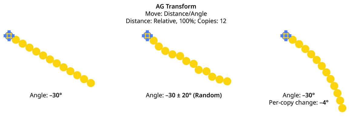
AG Transform Angle Absolute Examples
D. Per-copy Change Value Variation: Available when randomization is enabled; it is the maximum angular amount which is added to or subtracted from the per-copy change value to get the random value.
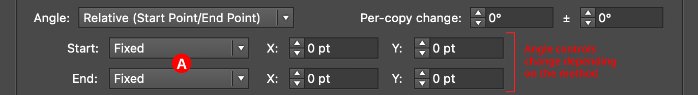
Relative (Start Point/End Point) submode: the offset angle is that of an imaginary line that starts at one point and ends at another. These points are not necessarily path anchor points, but may be specified using one of five different methods. Relative submodes are most useful when there are multiple objects in the selection that are being transformed. In this submode, the angle controls are as follows:
AG Transform Parameters Dialog, Angle Relative (Start End) Submode
A. Start/End Method: The dropdown menu for both the start and end points allows the choice between five different methods of specifying each point: Fixed, Relative to Bounds, Anchor Point, Position Along Path, or Tagged Path.
Fixed: With this method, the point is simply specified by its coordinates.

AG Transform Start End Point Fixed Controls
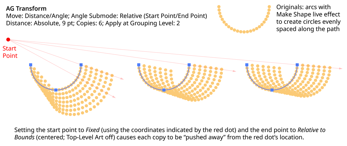
There would be no good reason to use Fixed for both the start and end points, because this would only result in the equivalent of an absolute angle. However, if the start point, say, uses Fixed, and the end point uses a different method which specifies the point relative to the art, then the copies will appear to “expand” from a common origin:
AG Transform Angle Fixed Start End
Relative to Bounds: With this method, the start or end point of the angle-determining line is located relative to the bounds of the original art, using the standard nine-box control. If the Apply at Grouping Level setting is set higher than zero, then the Top-Level Art checkbox becomes available. Turning off Top-Level Art means the bounds of each art object at the specified Grouping Level is used instead, which is usually desirable because each object will, in general, be offset at a different angle.

AG Transform Start End Point Relative to Bounds Controls
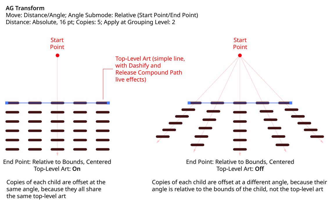
AG Transform Angle Top Level Art
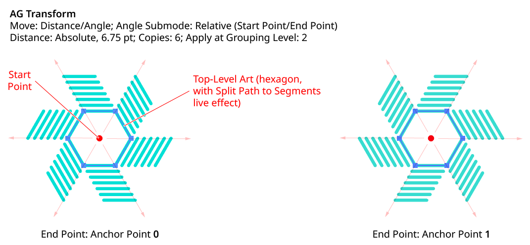
Anchor Point: With this method, the start or end point of the angle-determining line is located at an anchor point of the art object at the current Grouping Level, using the specified index (starting at zero). If the specified index is equal to or greater than the number of points in the path, then the last point on the path is used. If the art object is not a path or does not contain a path, the Relative to Bounds method is used instead.

AG Transform Start End Point Anchor Point Controls
AG Transform Angle Anchor Point
Position Along Path: With this method, the start or end point of the angle-determining line is located at the specified position (from 0% to 100%) along the path of the art object at the current Grouping Level. If the art object is not a path or does not contain a path, the Relative to Bounds method is used instead.

AG Transform Start End Point Position Along Path Controls
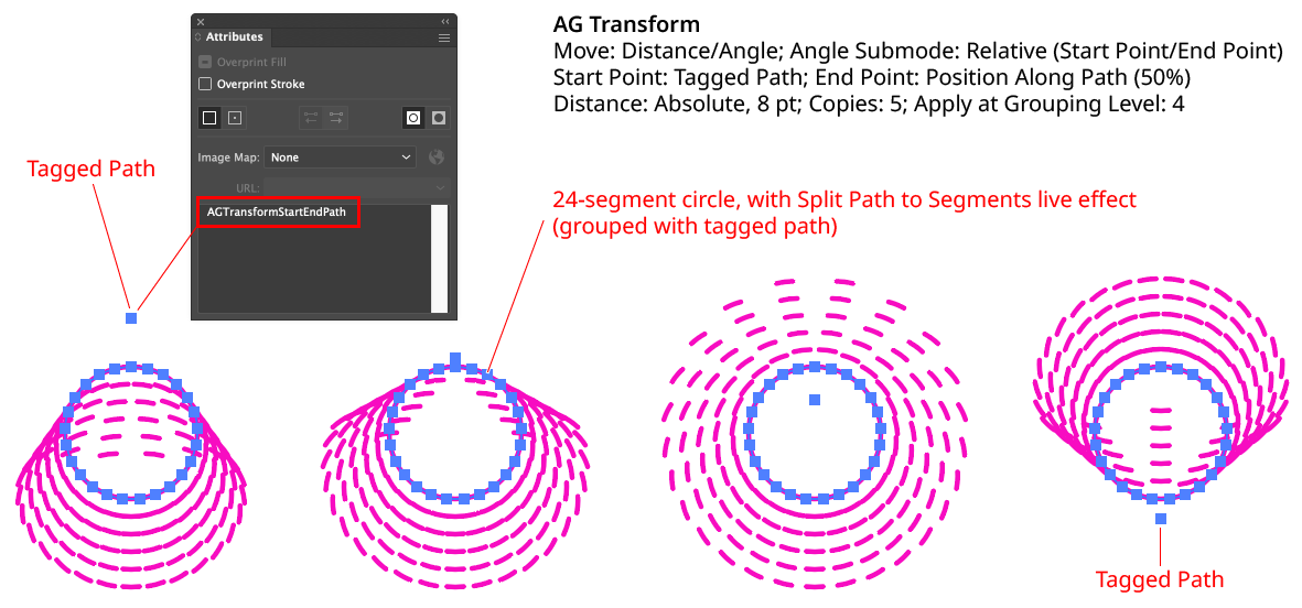
Tagged Path: With this method, the start or end point of the angle-determining line is located at the first anchor point of the path contained in the top-level group that has the note “AGTransformStartEndPath” (as entered on the native Attributes panel). It is customary to use a single-point path for this purpose, so the path won’t inadvertently be made visible. If no such path exists, AG Transform uses the first path it finds in the top-level art. If no paths at all exist, the Fixed location is used instead.

AG Transform Start End Point Tagged Path Controls
AG Transform Angle Tagged Path
Although similar to Fixed, the Tagged Path method allows the art to be moved around the artboard without changing its appearance, since the Tagged Path moves with it.
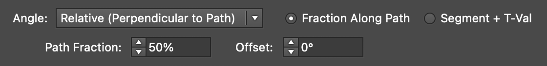
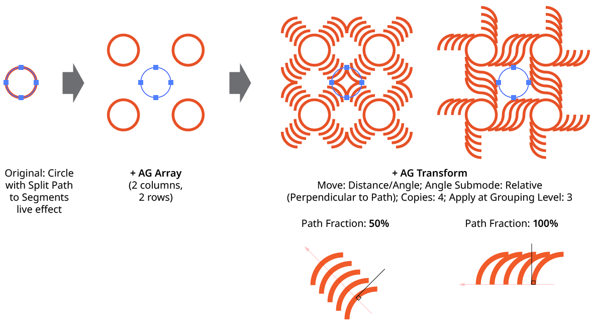
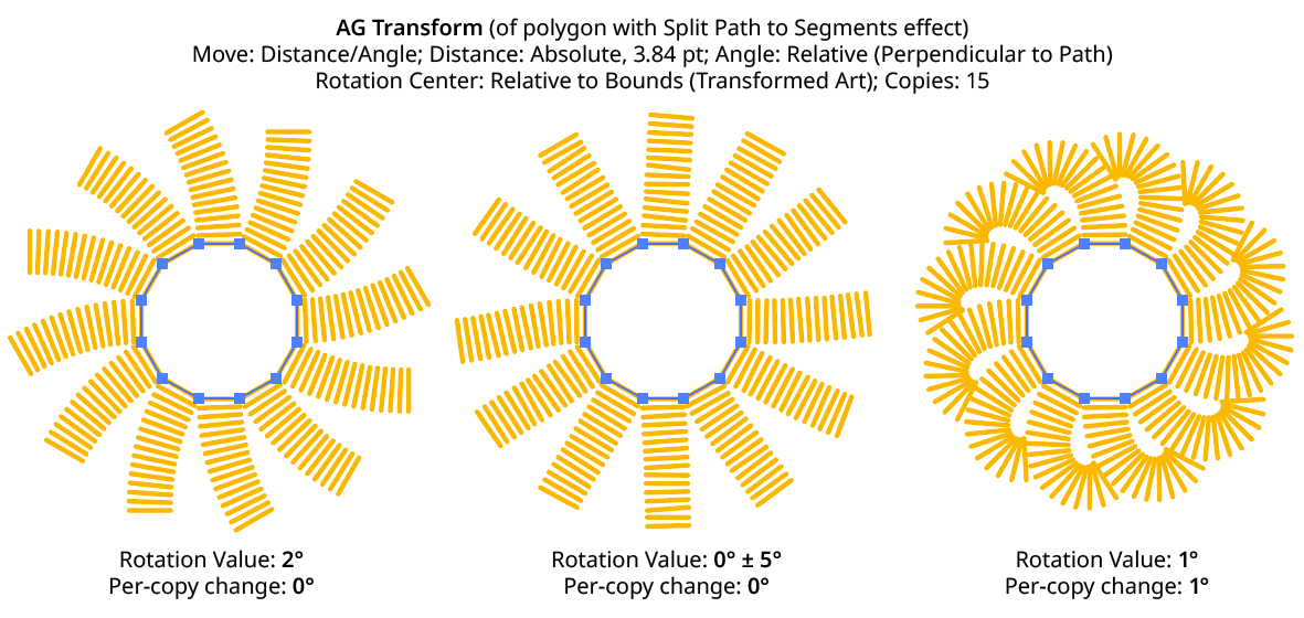
Relative (Perpendicular to Path) submode: the offset angle is perpendicular to the path of the art object at the current Grouping Level (if the art object is not a path or does not contain a path, an angle of 0° is used). The perpendicularity angle is calculated using a “right-hand” rule (i.e., to the right, relative to the direction of the path). Where the perpendicularity is calculated can be specified using either a fraction along the path, or a segment index plus t-value (the bezier-derived distance between the anchor point and the next anchor point). In this submode, the angle controls are as follows:
AG Transform Angle Perpendicular Path Fraction Controls
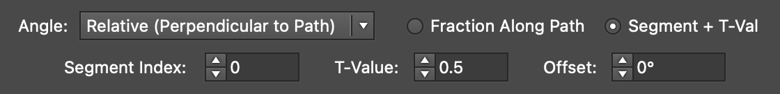
AG Transform Angle Perpendicular Index and T-Val Controls
AG Transform Angle Perpendicular to Path
Using either method (Fraction Along Path or Segment + T-Val), an additional angular offset to the perpendicular angle may be added. Using a value of 180°, for example, can be useful if the path’s direction is the opposite of what is expected.
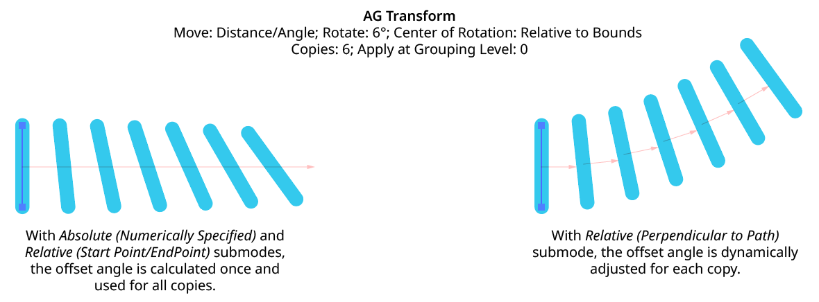
Although the offset angle is calculated once for the Relative (Start Point/End Point) submode and used for all subsequent copies, the angle for the Relative (Perpendicular to Path) submode is dynamically updated with each copy. Thus, if the art is rotated in addition to being offset, the offset angle will change to stay perpendicular to each copy.
AG Transform Angle Perpendicular to Path with Rotation
Rotate Section
The Rotate section of the dialog has the following controls:
AG Transform Parameters Dialog, Rotate Section
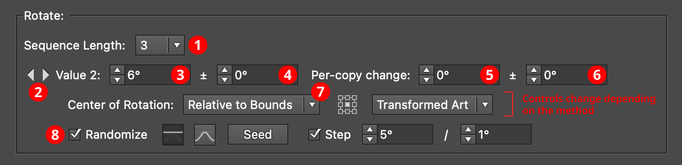
1. Rotation Sequence Length
By default (and ignoring randomization), each copy receives the same rotation value (as with the native Transform effect). However, AG Transform offers sequences, which allow up to 8 different rotation values. If the number of copies exceeds the length of the sequence, the values simply repeat in a cycle. Each member of a sequence shares the same randomization parameters.
AG Transform Rotation Sequence Examples
2. Previous/Next Offset Buttons
Available when the sequence length is set to a value other than 1. Clicking either button will move between the sequence’s values, allowing any of them to be edited.
3. Value/Base Value
The angular value for the current sequence index. When randomization is enabled, this value specifies the base angle to which a random amount is added or subtracted.
4. Base Value Variation
Available when randomization is enabled; it is the maximum angular value which is added to or subtracted from the base value to get the random value. For example, if the base value is set to 45°, and the random variation is set to 10°, then angles from 35° to 55° may be produced.
5. Per-copy Change Value
The angular amount to add to the base value for each new copy. For example, if the base value is set to 20°, and the per-copy change is set to 3°, then the first copy will be rotated 20°, the second at 23°, the third at 26°, and so on.
6. Per-copy Change Value Variation
Available when randomization is enabled; it is the maximum angular amount which is added to or subtracted from the per-copy change value to get the random value.
AG Transform Rotation Examples
7. Center of Rotation
The dropdown menu allows the choice between six different methods of specifying the center of rotation: Fixed, Relative to Bounds, Anchor Point, Position Along Path, Tagged Path, or Along Line.
Fixed: With this method, the center of rotation is simply specified by its coordinates.

AG Transform Center of Rotation Fixed Controls
This could be used to make multiple objects rotate around a common center, even if their position is subsequently adjusted:
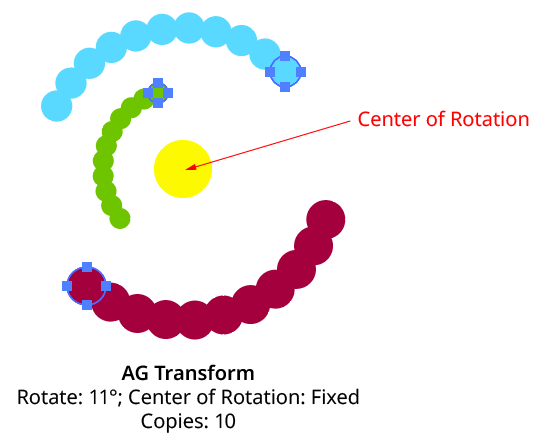
AG Transform Rotate Center Fixed
Relative to Bounds: This method (when used with Top-Level Art) is what the native Transform effect uses.

AG Transform Center of Rotation Relative to Bounds Controls
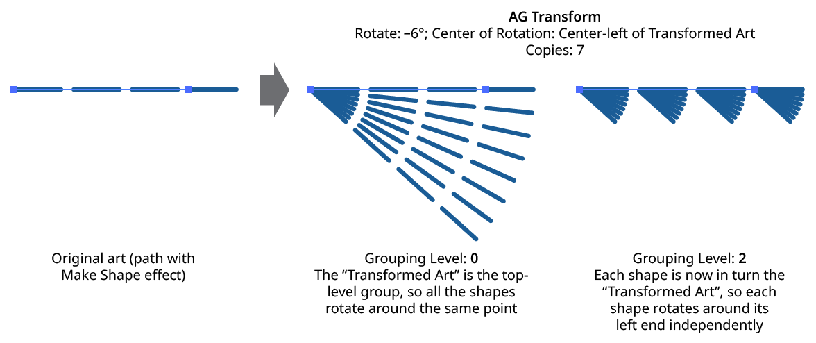
With this method, the center of rotation is located relative to the bounds of the specified art, using the standard nine-box control. The choices for the art type are Top-Level Art, Original Art, or Transformed Art. Top-Level Art is the art to which the AG Transform effect was applied (which may be a group). Original Art is the art at the specified Grouping Level which is being independently transformed, using its initial position for all copies. Transformed Art also refers to this art, but uses the transformed bounds for each copy, i.e., the center of rotation moves along with the copies.
To understand how changing the rotation center’s art type affects the results, it is helpful to understand the order of transform operations. For example, applying a native Transform effect with both a horizontal move and a rotation results in the left-hand image below and not the right-hand one — but why?
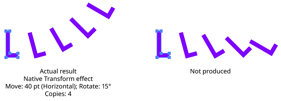
Native Transform Move Plus Rotate Example
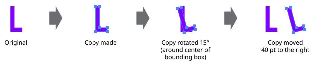
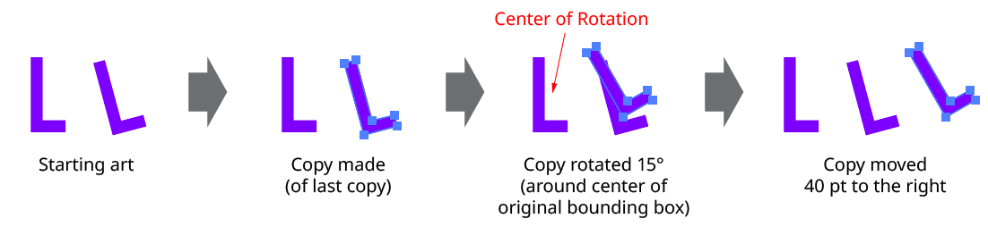
The answer is due to two factors: the order of the transform operations, and the method of locating the center of rotation for each copy. For both the native Transform effect and AG Transform, each copy of the art is first scaled, then rotated, and finally moved (offset). The native Transform effect locates the center of rotation using the bounding box of the original art, and that center is used for all subsequent copies. Thus, the transform could be manually created as follows: Starting with the original art, a copy is made in place which is then rotated 15° around the center of rotation (the bounding box center). Then it is offset 40 pt to the right.
Native Transform Move Plus Rotate Manual Creation
This process is repeated for the second copy. Importantly, the center of rotation remains located at the center of the bounding box of the original art.
Native Transform Move Plus Rotate Manual Creation with Multiple Copies
The same steps are followed for each subsequent copy, which leads to the results shown originally.
AG Transform can be made to act like the native Transform effect for rotation by setting the Center of Rotation method to Relative to Bounds and the art type to Top-Level Art. However, the other two art types offer additional options:
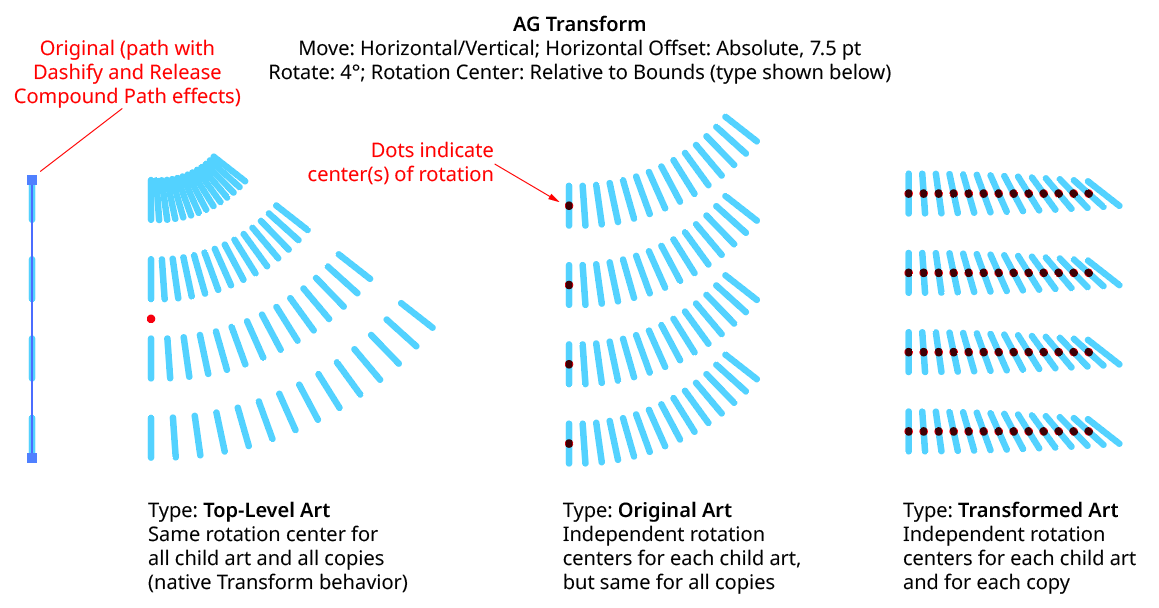
AG Transform Rotate Center Relative to Bounds Examples
Anchor Point: With this method, the center of rotation is located at the specified anchor point of the art at the specified grouping level. The rotation point is transformed for each copy, along with the art. If the art does not contain a path, the Relative to Bounds method will be used instead.

AG Transform Center of Rotation Anchor Point Controls
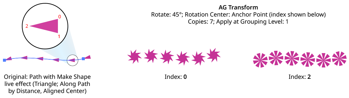
AG Transform Rotate Center Anchor Point Examples
Position Along Path: With this method, the center of rotation is located along the path of the art (from 0% to 100%) at the specified grouping level. The rotation point is transformed for each copy, along with the art. If the art does not contain a path, the Relative to Bounds method will be used instead.

AG Transform Center of Rotation Position Along Path Controls
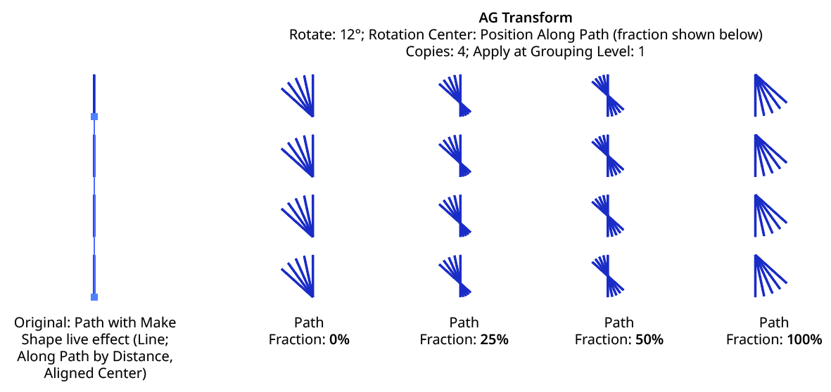
AG Transform Rotate Center Position Along Path Examples
Tagged Path: With this method, the center of rotation is located at the first anchor point of a path contained in the top-level group that has the note “AGTransformRotatePath” (as entered on the native Attributes panel). It is customary to use a single-point path for this purpose, so the path won’t inadvertently be made visible. If no such path exists, AG Transform uses the first path it finds in the top-level art. If no paths at all exist, the Relative to Bounds method will be used instead.

AG Transform Center of Rotation Tagged Path Controls
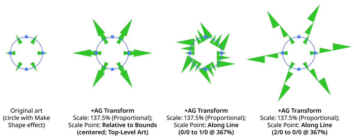
Along Line: With this method, the center of rotation is located along an imaginary line that passes through two points which are located using anchor point indices and t-values in the path art at the specified grouping level. The rotation point is transformed for each copy, along with the art. If the art does not contain a path, the Relative to Bounds method will be used instead.

AG Transform Rotate Center Along Line Controls
A. Start Index: The index of the anchor point used to locate the start of the imaginary line.
B. Start T-Val: The t-value (bezier-derived distance between the anchor point and the next anchor point, ranging from 0 to 1) of the start point.
C. End Index: The index of the anchor point used to locate the end of the imaginary line.
D. End T-Val: The t-value (bezier-derived distance between the anchor point and the next anchor point, ranging from 0 to 1) of the end point.
E. Fraction: The position of the center of rotation, as a fraction of the distance between the start point of the imaginary line and the end point. Values between 0% and 100% would put this point between the start and end, but the value can also be negative or greater than 100% to put the point outside this interval.
The Along Line method is similar to the Relative to Bounds method in that the center of rotation is always relative to the artwork. However, while Relative to Bounds only offers nine distinct positions, Along Line can specify an infinite number of such positions.
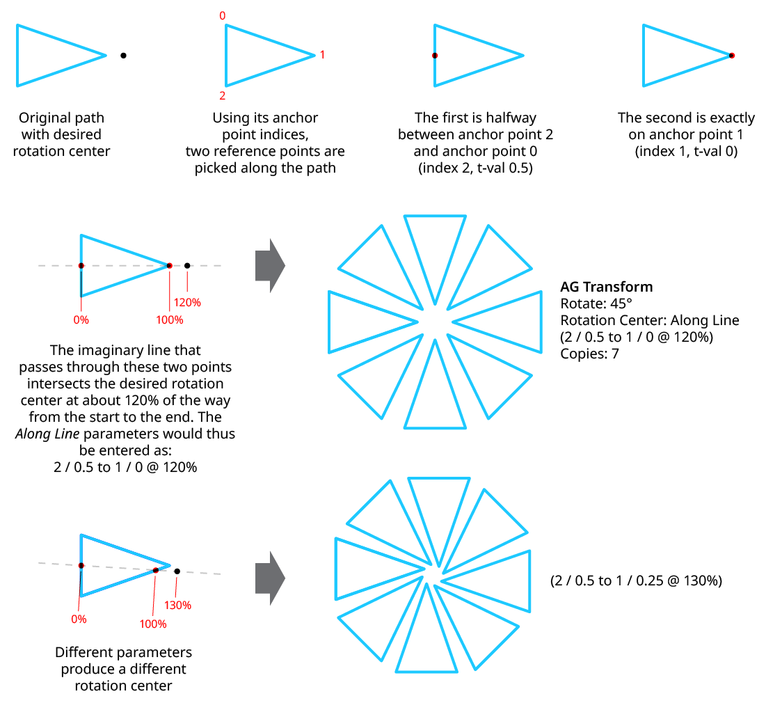
AG Transform Rotate Center Along Line Examples
8. Randomize
Randomization works the same way in the Rotate section of the dialog as it does in the Angle area of the Move section (when in Distance/Angle mode). Step values can be set for both the regular rotation value and for the per-copy change value.
Scale Section
The Scale section of the dialog has the following controls:
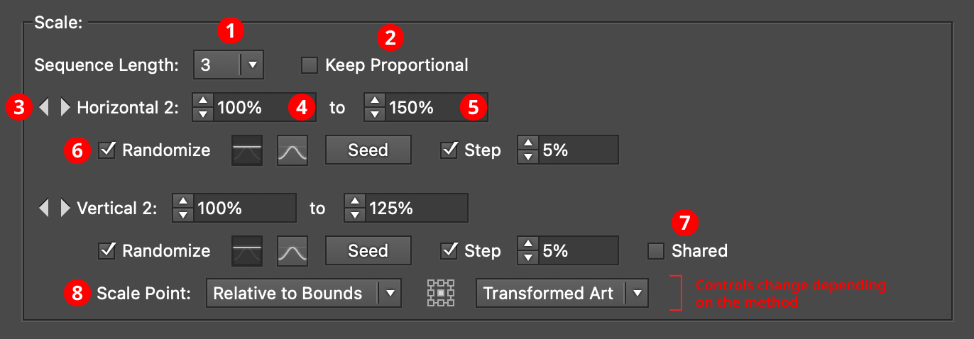
AG Transform Parameters Dialog - Scale Section
1. Rotation Sequence Length
By default (and ignoring randomization), each copy receives the same scaling value (as with the native Transform effect). However, AG Transform offers sequences, which allow up to 8 different scaling values. If the number of copies exceeds the length of the sequence, the values simply repeat in a cycle. Each member of a sequence shares the same randomization parameters.
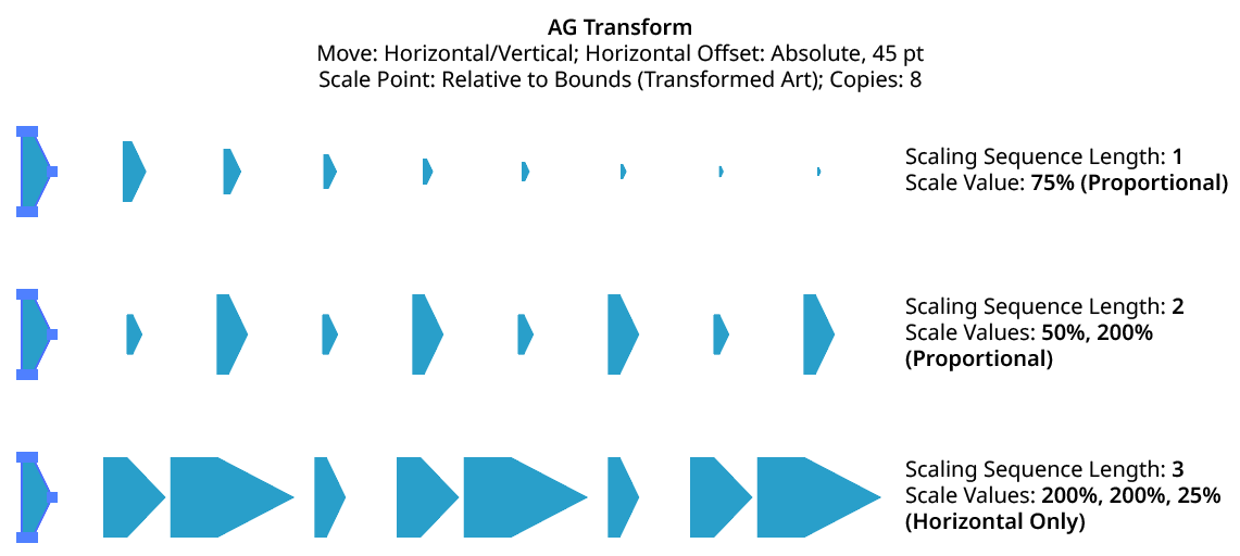
AG Transform Scaling Sequence Examples
2. Keep Proportional
When enabled, scaling will always be proportional (the vertical scaling values will be automatically set to match the horizontal scaling values).
3. Previous/Next Offset Buttons
Available when the sequence length is set to a value other than 1. Clicking either button will move between the sequence’s values, allowing any of them to be edited.
4. Value/Minimum Value
The horizontal (or vertical) scaling value for the current sequence index, from –10000% to 10000%. Negative values have the effect of flipping the object across the corresponding axis (the same as using the Reflect X or Reflect Y checkboxes in the native Transform dialog). When randomization is enabled, this value specifies the minimum value that may be randomly produced.
5. Maximum Value
Available when randomization is enabled; it specifies the maximum horizontal (or vertical) scaling value that may be randomly produced for the current sequence index.
6. Randomize
Randomization works the same way in the Scale section of the dialog as it does in the Move section. Both horizontal and vertical scaling can have independent randomization parameters.
AG Transform Random Scale
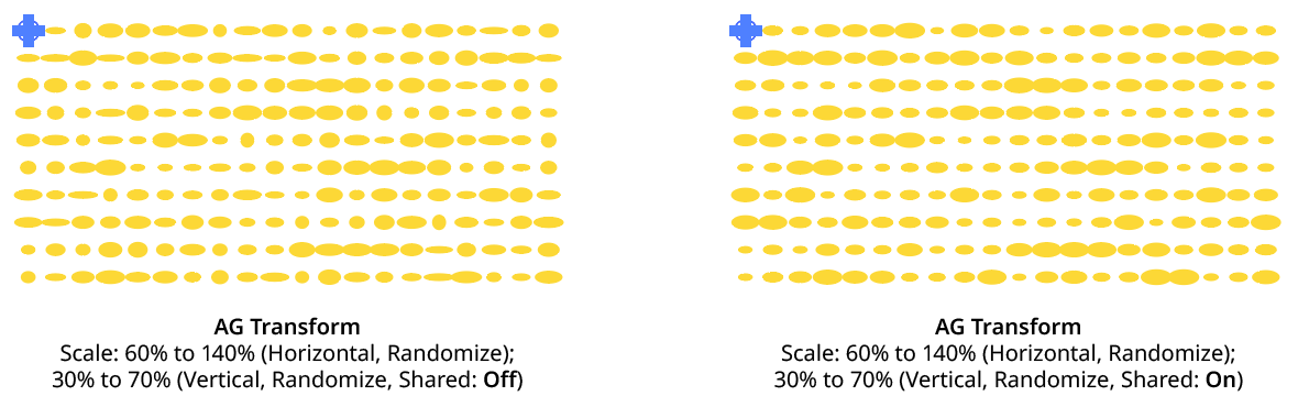
7. Shared
When enabled, the random number for each copy (i.e., its random position between the specified minimum and maximum) will be the same for the vertical scaling as the horizontal scaling, allowing the transformed aspect ratio of each copy to be maintained.
AG Transform Random Scale (Non-Shared Vs. Shared)
8. Scale Point
Just as with specifying the Center of Rotation, the dropdown menu allows the choice between six different methods of specifying the point through which the art is scaled: Fixed, Relative to Bounds, Anchor Point, Position Along Path, Tagged Path, or Along Line. See Center of Rotation in the Rotate section for an explanation of the methods.
AG Transform Scale Point Examples
Bottom Section
The Bottom section of the dialog has the following controls:
AG Transform Parameters Dialog - Bottom Section
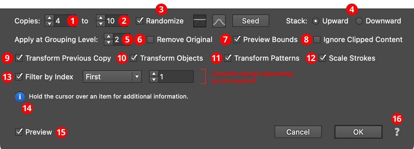
1. Copies
The number of copies to make for each art object at the specified grouping level. This is the same as the setting in the native Transform effect. When copy randomization is enabled, this value represents the minimum number of copies that may be randomly produced.
2. Maximum Copies
Available when copy randomization is enabled; it specifies the maximum number of copies that may be randomly produced.
3. Copies Randomize
When randomization is enabled, the number of copies is not fixed for each object, but is chosen randomly between the specified minimum and maximum values. The distribution of those values (linearly or in a Gaussian manner) can be specified, as well as the random seed.
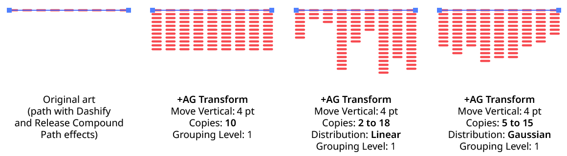
AG Transform Copy Randomization Examples
4. Stack
Specifies whether each copy is created upward or downward in the stacking order (the native Transform effect always stacks downward).
AG Transform Stacking Order
5. Apply at Grouping Level
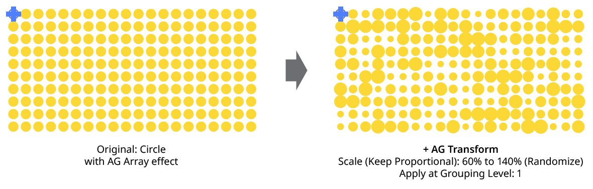
Unless a live effect is applied above all strokes and fills (a “pre” effect), or inside a stroke or a fill and above other live effects, the art object internally passed to it is always a group. And this group may contain other groups, and so on. The Grouping Level controls the level at which the effect is applied, which affects what elements in the hierarchy get different random transformations as well as how the center of rotation and scale point are calculated. The Grouping Level can range from 0 (representing the top-level art) to 29 (the deepest level of group nesting allowed in Illustrator).
In the simplest case (when AG Transform is applied to a single stroked-and-filled path), the live effect mechanism separates the stroke from the fill, and passes a stroke-only path and a fill-only path to the live effect in a group. So while a Grouping Level of 0 would apply the same transformation to the stroke and fill (because it is applied to the top-level group), a Grouping Level of 1 would cause it to consider the stroke and fill as separate objects, and if randomization was on, they would get different random values:
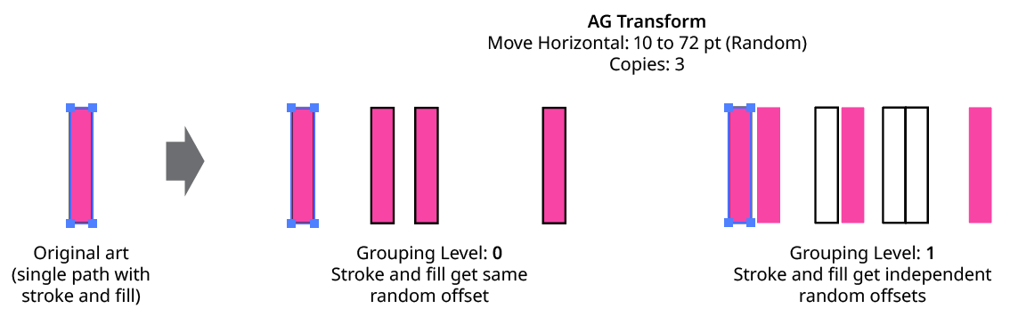
AG Transform Grouping Level on Simple Path
Next, consider the case of applying AG Transform to a group of stroked and filled paths. This top-level group may or may not have its own stroke and/or fill in its appearance. Here, the group passed to the effect has three groups inside it. One is composed of the paths with group level strokes (if there is no group level stroke, these would have no stroke or fill); another is composed of the paths with group level fills (similarly, if there is no group level fill, these would also have no stroke or fill); and the last is composed of the original paths in the group (and here, strokes and fills are not broken apart).
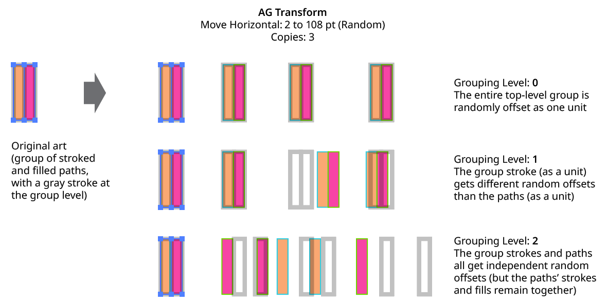
AG Transform Grouping Level on Group of Paths
In general, each nested group in the original art requires two Grouping Levels to “dig into,” due to the fact that a group stroke or fill can be present at each level. Because it can be difficult to anticipate what Grouping Level to use because the live effect mechanism can be complicated, it is recommended to simply increase the Grouping Level until the results are what is desired (modifying the seed or seeds, if necessary, to see what is really changing independently). Setting the Grouping Level above the highest “valid” value will not cause a problem.
AG Transform Grouping Level and Rotation Center
6. Remove Original
Available if the number of copies is greater than zero. When enabled, the original art to which the effect was applied will be suppressed in its final appearance. This is often useful when using random transformations but the original is regular and spoils the random look.
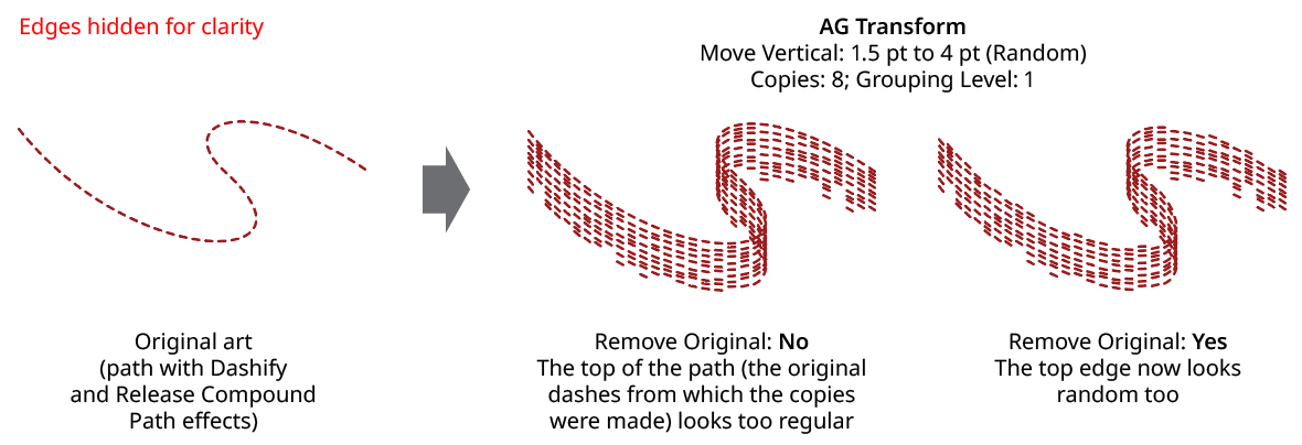
AG Transform Remove Original
7. Use Preview Bounds
Overrides the general preference of the same name. When enabled, the strokes of the artwork are included in its bounding box, which affects the position of the Center of Rotation or Scale Point when they are set to Relative to Bounds:
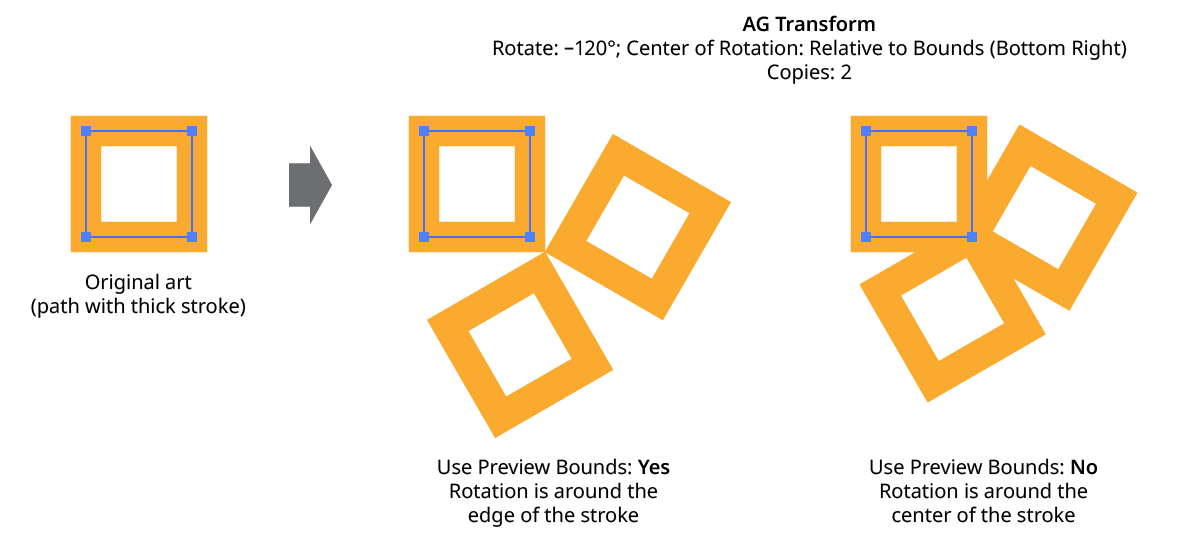
AG Transform Use Preview Bounds
8. Ignore Clipped Content
When enabled, and the art is a clip group, then only the clipping path is used for the purposes of bounds determination. This affects, for instance, the Move offsets when in Relative mode, or the position of the Center of Rotation or Scale Point when they are set to Relative to Bounds.
9. Transform Previous Copy
By default (and as with the native Transform effect), each copy after the first is created by transforming the previous copy. However, when using randomization, it can sometimes be useful to always start with the original art’s position and transform it to create each copy:
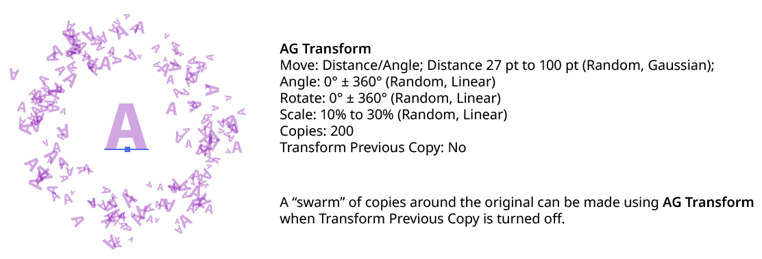
AG Transform Transform Previous Copy
10. Transform Objects
This option works the same as that for the native Transform effect. When disabled, only the pattern(s) contained in the art are transformed.
11. Transform Patterns
This option works the same as that for the native Transform effect. When disabled, pattern(s) contained in the art are not transformed along with the art.
AG Transform Objects and Patterns
12. Scale Strokes
When disabled, and the AG Transform contains scaling, strokes within the artwork will retain their original weight.
AG Transform Scale Strokes
13. Filter By Index
When enabled, each art object’s index is used to determine whether it should be transformed, using one of seven different methods. The index is simply an integer sequentially assigned to each object at the specified Grouping Level in the order it is encountered, starting with zero for the first object. Generally, the index increases going downwards in the stacking order; however, other live effects present in the appearance stack may change this order, sometimes randomly (such as PathFinder effects). Additionally, objects may be created which are invisible in the final appearance if they have no fill or stroke. The available By Index methods are as follows:
a. First: Only the first n objects are affected, where n is the specified value.

AG Transform Filter by Index - First Controls
b. Last: Only the last n objects are affected, where n is the specified value.

AG Transform Filter by Index - Last Controls
AG Transform Filter by Index - First, Last
c. First or Last: Only the first and last objects are affected.
d. Odd: Only objects with an odd index (1, 3, 5, 7...) are affected.
e. Even: Only objects with an even index (0, 2, 4, 6...) are affected.
AG Transform Filter by Index - Odd, Even
f. Pattern: Creates a repeating pattern of matching indices based on the three pattern parameters.

AG Transform Filter by Index - Pattern Controls
Initial Skip specifies the number of indices to skip over at the start (art with these indices will not be affected). Then, Match specified the number of indices that will match and therefore be affected. Finally, Skip specifies the number of indices to skip over following the matching indices. When the total of the values in the three parameters is less than the number of eligible art objects, the pattern repeats, using the Match and Skip values in alternation.
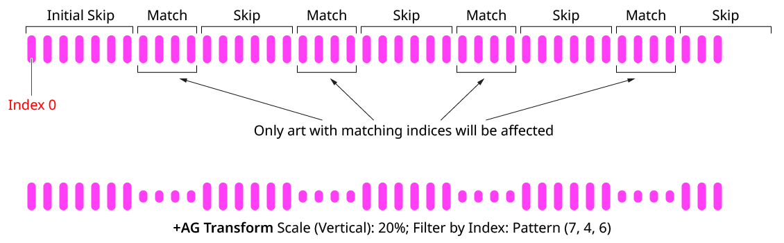
AG Transform Filter by Index - Pattern
g. Randomly: Each art object has the specified random chance (from 0% to 100%) of being affected. The parameter has an independent seed value. Just as with move/rotate/scale seed values, clicking the button picks a new seed, thereby changing the look of the artwork. To view or specify the seed number directly,
Option/Alt-clickthe button. This lets you recreate a previously-generated look.

AG Transform Filter by Index - Randomly Controls

AG Transform Filter by Index - Randomly
14. Informational area
Shows a brief description of each control when the cursor is being hovered over it.
15. Preview
As with all live effects, when enabled, changing a parameter will immediately update the artwork while the dialog is still open.
16. Help Button
Opens the help documentation in the Astute Manager. If this does not automatically appear, please ensure your Astute Manager is running first.
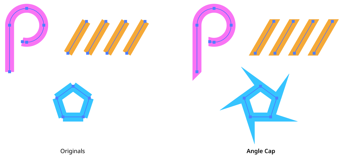
Angle Cap Live Effect
Angle Cap is an Astute Graphics live effect for stroked, open paths that allows for angled end caps, where the flat end of the stroke runs at an adjustable angle to the perpendicular of the path. The angle can be fixed at a certain value (for example, always horizontal), or can be relative to the path’s angle.
As with most live effects, Angle Cap appears in the main menu, under Effect > AG Utilities. It can also be applied directly from the Appearance panel using the “Add New Effect” button at the bottom of the panel.
Angle Cap Live Effect Example
Angle Cap Parameters Dialog
After applying the live effect using the menu item (or when clicking on the existing effect in the Appearance panel to edit it), the parameters dialog will appear:
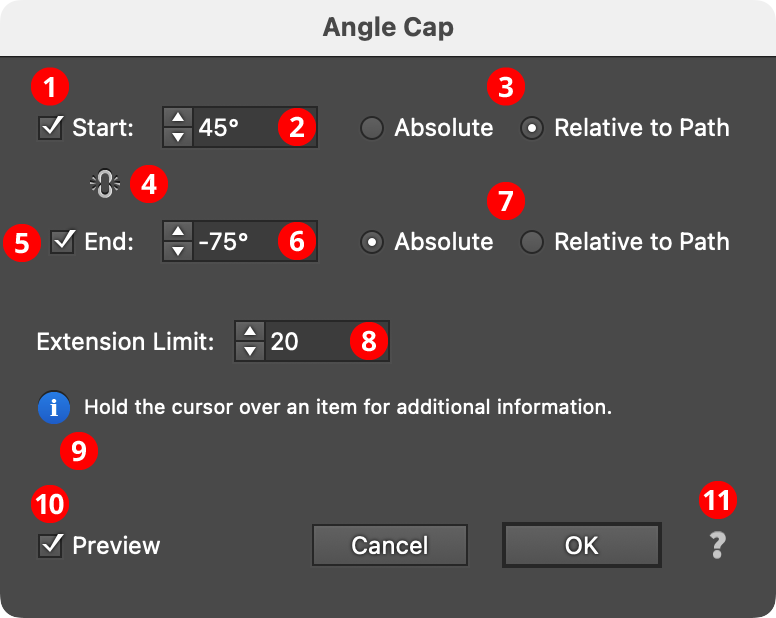
Angle Cap Parameters Dialog
1. Start
The Start checkbox enables or disables modification of the stroke cap at the start of the path.
2. Start Angle
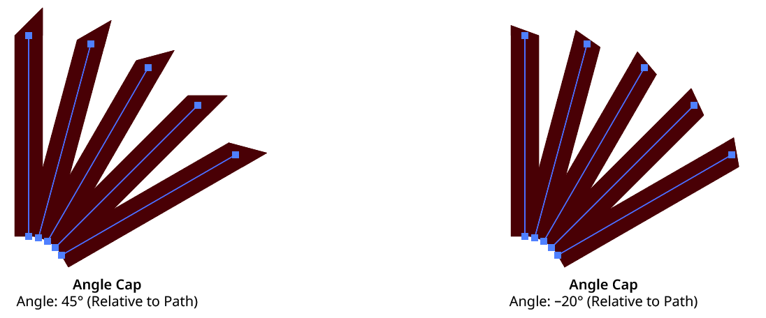
Specifies the angle of the end of the stroke’s cap. In Absolute mode, this angle is fixed (does not depend on the path angle) and can range from –360° to 360° using the normal Illustrator convention of angles (0° is to the right):
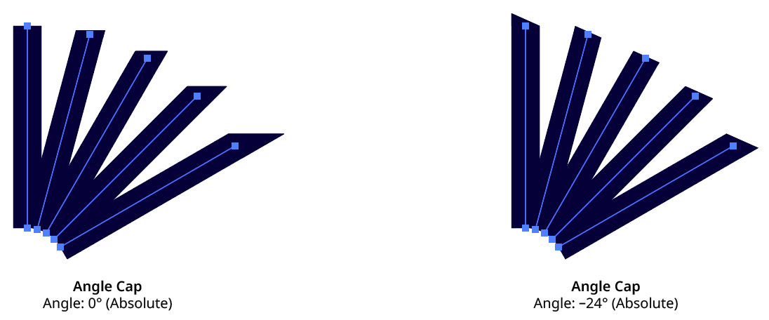
Angle Cap Absolute Mode
In Relative to Path mode, the angle is relative to a line drawn perpendicular to the path at its tip, and can range from –90° to 90°, where 0° means no change from the normal perpendicular angle:
Angle Cap Relative to Path Mode
3. Start Absolute/Relative
Specifies the mode of the start cap angle (see Start Angle).
4. Link Start & End
Clicking on the icon toggles its state. When “linked,” making changes to either the Start or End parameters will simultaneously affect the opposite side.
5. End
The End checkbox enables or disables modification of the stroke cap at the end of the path.
6. End Angle
As per the Start angle, but for the end (last anchor point) of the path.
7. End Absolute/Relative
Specifies the mode of the end cap angle (see Start Angle).
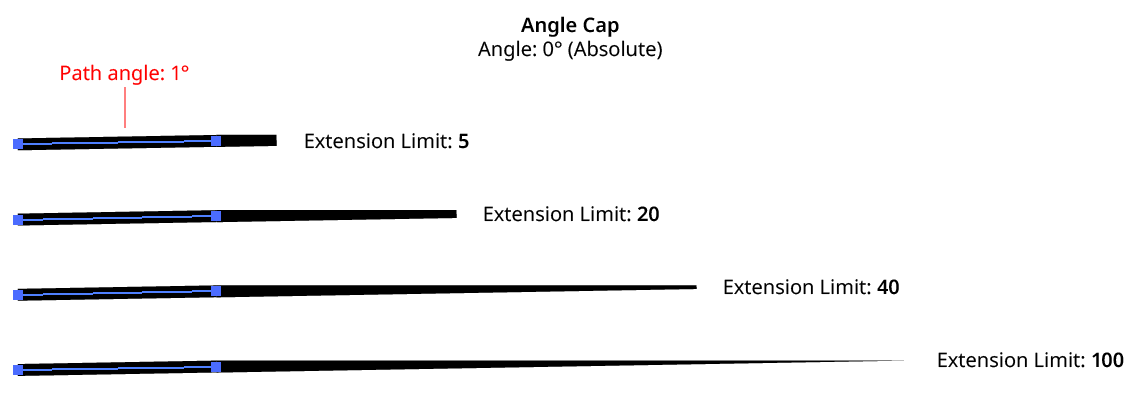
8. Extension Limit
Similar to the native miter limit for corner joins, the Extension Limit is necessary to keep an angled cap from extending out infinitely as the cap’s angle gets closer and closer to the path’s tangent angle. The value represents the maximum length of the cap as a multiple of the path’s width, and can range from 5 to 500.
Angle Cap Extension Limit
9. Informational area
Shows a brief description of each control when the cursor is being hovered over it.
10. Preview
As with all live effects, when enabled, changing a parameter will immediately update the artwork while the dialog is still open.
11. Help Button
Opens the help documentation in the Astute Manager. If this does not automatically appear, please ensure your Astute Manager is running first.
Angle Cap Considerations
Angle Cap: Inside, Outside, and Variable Width Strokes
Because these types of strokes are actually converted to closed, filled paths inside the live effect mechanism, Angle Cap cannot be used with them.
Angle Cap: Dashed Strokes
When Aligned dashes are used, the dashes at the start and end of the path are generally converted to separate open paths inside the live effect mechanism, and thus will receive angle caps of their own, producing unexpected results. To put angle caps on each dash, use the Astute Graphics Dashify live effect instead of a dashed stroke.

Angle Cap with Dashes
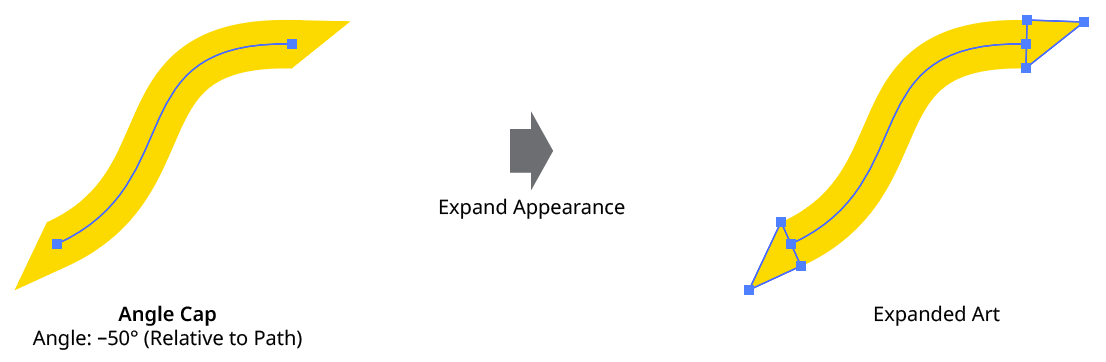
Angle Cap: Strokes with Gradients
A plugin cannot actually change a stroke’s caps in Illustrator, so the Angle Cap live effect simulates them by placing an appropriately-shaped polygon at the end(s) of the path. This may be seen by expanding the live effect:
Angle Cap Expanded View
If the stroke has a gradient applied (the normal, “within the stroke” type — gradients along or across the stroke are converted to meshes inside the live effect mechanism and will not work with Angle Cap), Illustrator’s method of auto-positioning gradients will typically result in the caps visually not being seamless with the stroke. One way to remedy this is by placing the Angle Cap effect within the stroke and adding (directly above it) a native Pathfinder Add effect and an Astute Graphics Segment Removal effect (to change the path, which becomes a closed path after the Add effect, back to open).
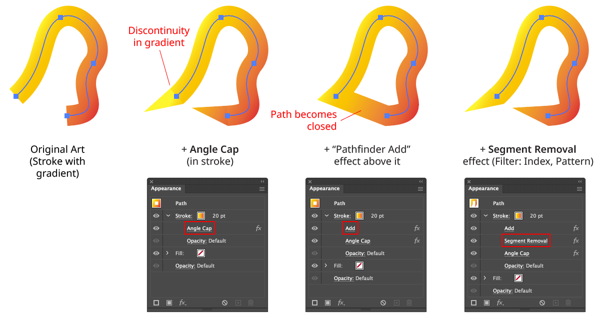
Angle Cap with Gradients
Note that with this method, because the native Add effect can change the starting point of the path, it may be necessary to adjust the Pattern/Initial Skip value in the Segment Removal effect to target the correct segment to remove:
Angle Cap with Gradient - Segment Removal Example
Angle Cap: Strokes with Round or Projecting Caps
Angle Cap handles these types of existing caps by simply extending the cap polygon(s) to cover them.
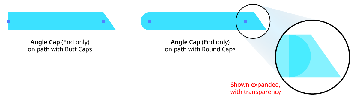
Angle Cap with Round Caps
Close Path Live Effect
Close Path is an Astute Graphics live effect for open paths that closes them using one of three methods: using the existing handles (if any); with a straight segment; or with a smooth curve. If using a smooth curve, the scaling of the handles can be specified.
As with most live effects, Close Path appears in the main menu, under Effect > AG Utilities. It can also be applied directly from the Appearance panel using the “Add New Effect” button at the bottom of the panel.
Close Path Parameters Dialog
After applying the live effect using the menu item (or when clicking on the existing effect in the Appearance panel to edit it), the parameters dialog will appear:
Close Path Parameters Dialog
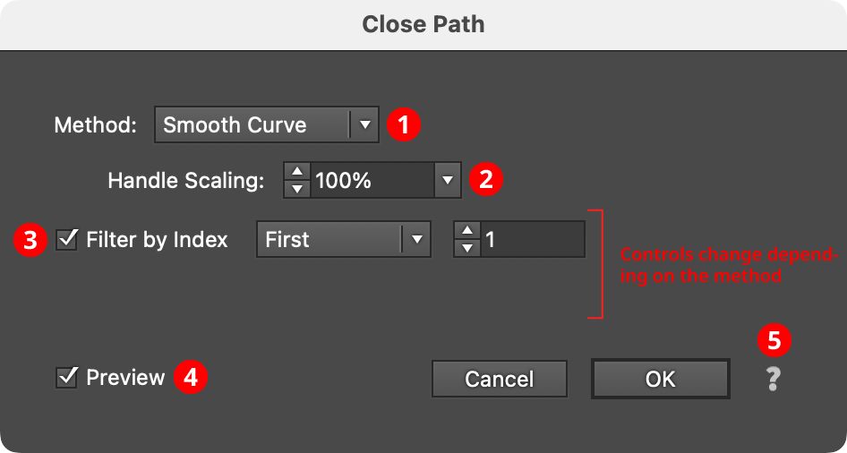
1. Method
Specifies how the path will be closed. When set to Existing Handles, the path is simply marked as closed and the closing segment incorporates the outfacing handles (if any) that were present on the start and last segment of the open path (this may therefore result in a straight or curved segment, depending on those handles). When set to Straight Segment, the path is closed with a straight, handleless segment. When set to Smooth Curve, the path is closed using a curved bezier segment that joins the existing path smoothly (i.e., at the join locations, the new segment and the existing path have the same tangential angles).
Close Path Method
2. Handle Scaling
Available when the method is set to Smooth Curve. It controls the length of the generated handles, as a percentage of the default value. Higher numbers produce a curve that “bulges” more.
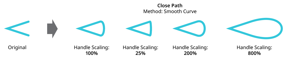
Close Path Handle Scaling
3. Filter By Index
When enabled (and the effect has been applied to a group or is inside a live effect stack which has internally created multiple objects), each art object’s index is used to determine whether it should be affected by the live effect, using one of seven different methods. The index is simply an integer sequentially assigned to each object in the order it is encountered, starting with zero for the first object. Generally, the index increases going downwards in the stacking order; however, other live effects present in the appearance stack may change this order, sometimes randomly (such as PathFinder effects). Additionally, objects may be created which are invisible in the final appearance if they have no fill or stroke. The available By Index methods are as follows:
a. First: Only the first n objects are affected, where n is the specified value.

Close Path Filter by Index First Controls
b. Last: Only the last n objects are affected, where n is the specified value.

Close Path Filter by Index Last Controls
c. First or Last: Only the first and last objects are affected.
d. Odd: Only objects with an odd index (1, 3, 5, 7...) are affected.
e. Even: Only objects with an even index (0, 2, 4, 6...) are affected.

Close Path Filter by Index, First, Last, Odd and Even
f. Pattern: Creates a repeating pattern of matching indices based on the three pattern parameters.

Close Path Filter by Index Pattern Controls
Initial Skip specifies the number of indices to skip over at the start (art with these indices will not be affected). Then, Match specified the number of indices that will match and therefore be affected. Finally, Skip specifies the number of indices to skip over following the matching indices. When the total of the values in the three parameters is less than the number of eligible art objects, the pattern repeats, using the Match and Skip values in alternation.
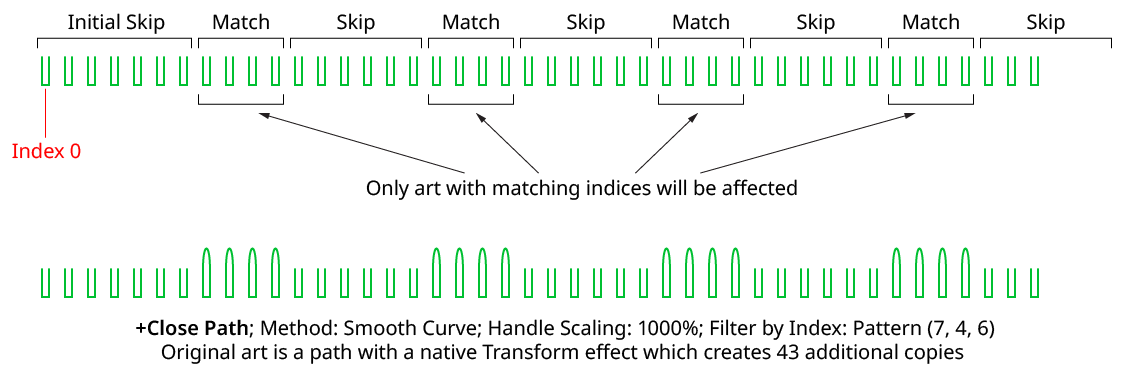
Close Path Filter by Index Pattern
g. Randomly: Each art object has the specified random chance (from 0% to 100%) of being affected. Clicking the Seed button picks a new random seed, thereby changing the look of the artwork. To view or specify the seed number directly,
Option/Alt-clickthe button. This lets you recreate a previously-generated look.

Close Path Filter by Index Randomly Controls
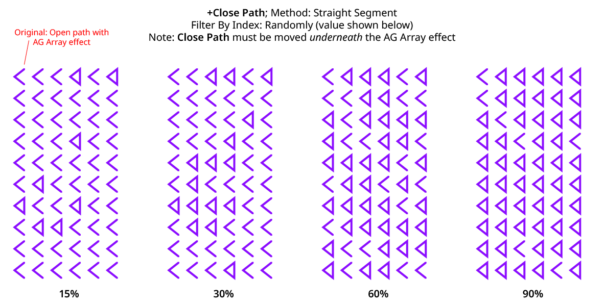
Close Path Filter by Index Randomly
4. Preview
As with all live effects, when enabled, changing a parameter will immediately update the artwork while the dialog is still open.
5. Help Button
Opens the help documentation in the Astute Manager. If this does not automatically appear, please ensure your Astute Manager is running first.
Convert to Smooth Live Effect
Convert to Smooth is an Astute Graphics live effect for paths that changes the anchor points in the artwork to smooth type, automatically adding and adjusting handles where needed.
As with most live effects, Convert to Smooth appears in the main menu, under Effect > AG Utilities. It can also be applied directly from the Appearance panel using the “Add New Effect” button at the bottom of the panel.
Convert to Smooth Parameters Dialog
After applying the live effect using the menu item (or when clicking on the existing effect in the Appearance panel to edit it), the parameters dialog will appear:

Convert to Smooth Parameters Dialog
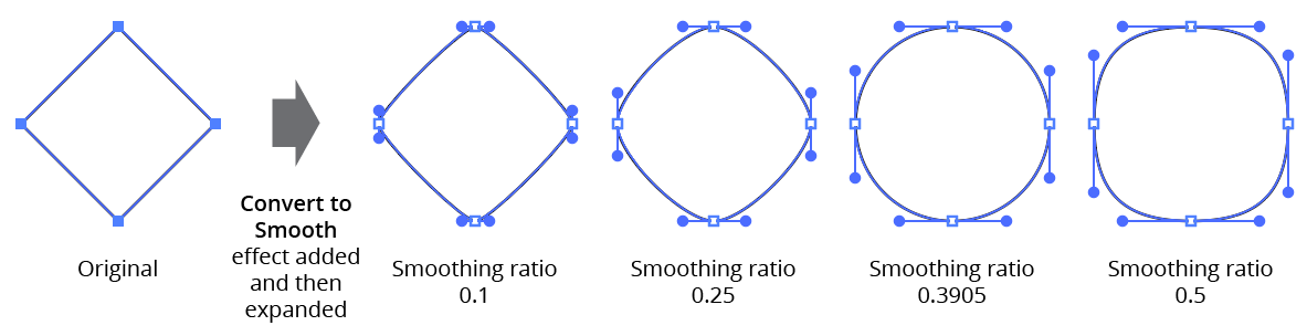
1. Smoothing Ratio
Controls the lengths of any newly-generated handles. The smoothing ratio can range from 0.01 to 0.5, with values between 0.3 and 0.4 generally give the smoothest looking curves; a value of 0.3905 will convert a square to a circle.
AG Utilities Live Effects - Convert to Smooth Ratios
2. Handleless Points Only
When enabled, only anchor points that have no handles will be converted to smooth points with new handles.
3. Preview
As with all live effects, when enabled, changing a parameter will immediately update the artwork while the dialog is still open.
4. Help Button
Opens the help documentation in the Astute Manager. If this does not automatically appear, please ensure your Astute Manager is running first.
Dashify Live Effect
Dashify is an Astute Graphics live effect for paths that breaks them into multiple segments that, if stroked, have the same look as native dashes. But unlike native dashes, when a path with Dashify is expanded, each dash is converted to a short, open section of a compound path rather than an outlined, filled and closed path. Additionally, Dashify supports five independent lengths for pairs of dashes and gaps, an additional alignment mode for open paths, and randomization options.
As with most live effects, Dashify appears in the main menu, under Effect > AG Utilities. It can also be applied directly from the Appearance panel using the “Add New Effect” button at the bottom of the panel.
Dashify Parameters Dialog
After applying the live effect using the menu item (or when clicking on the existing effect in the Appearance panel to edit it), the parameters dialog will appear:
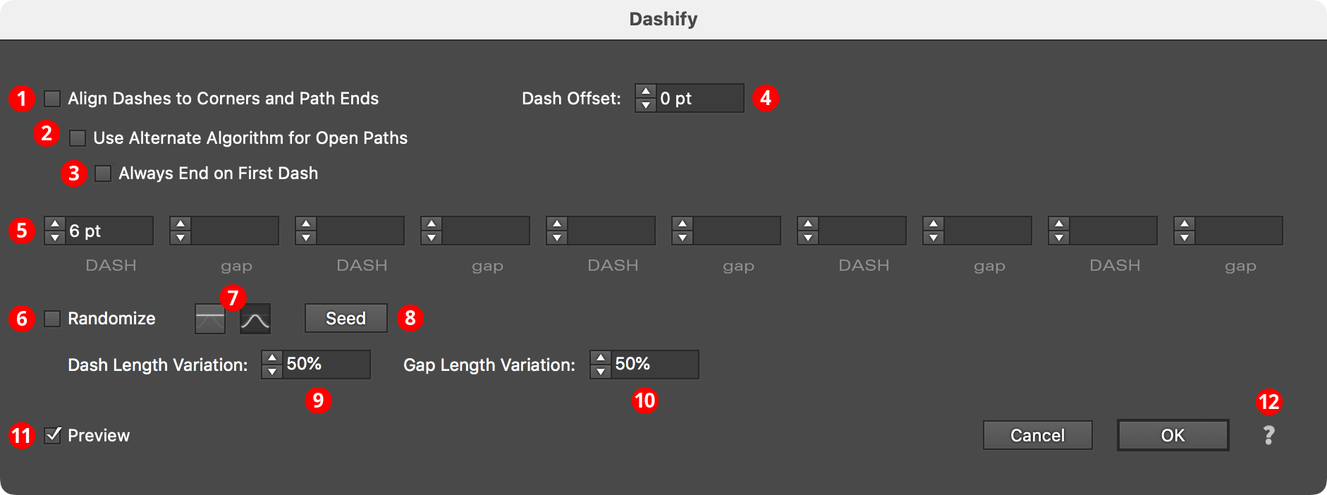
Dashify Parameters Dialog
1. Align Dashes to Corners and Path Ends
When enabled, dashes are aligned in the same manner as the native dashes are aligned using the native Stroke panel’s “Align” button. This may cause the absolute size of each dash and gap to be changed slightly.
2. Use Alternate Algorithm for Open Paths
Available when Align Dashes to Corners and Path Ends is enabled. When enabled, dashes are aligned such that each end of the open path gets a full dash rather than the half-dash that the native algorithm produces. Interior corners will be ignored for alignment purposes.
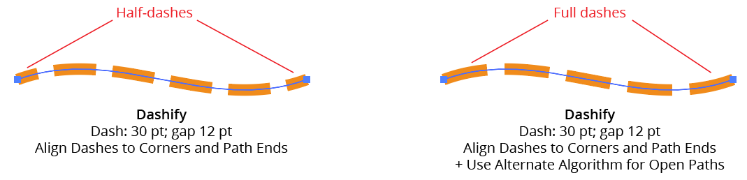
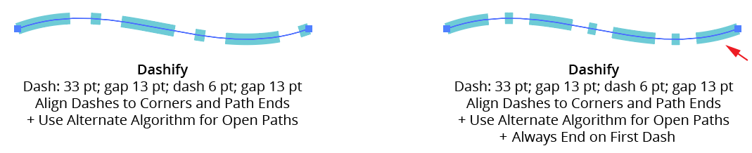
AG Utilities Live Effects - Dashify Alignment
3. Always End on First Dash
Available when the Alternate Algorithm for Open Paths is being used. When enabled, the dashed path will not only start with the first dash in the pattern but will also end with it:
AG Utilities Live Effects - Dashify Alignment (Always end on first dash)
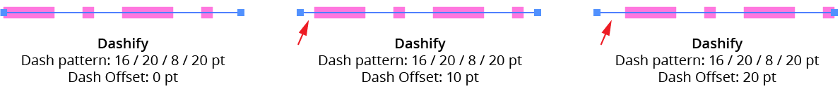
4. Dash Offset
Shifts the starting position of the dash pattern along the path. Positive values move the pattern in the path’s direction while negative values move it in the opposite direction. Dash Offset is not available when Align Dashes to Corners and Path Ends is enabled.
AG Utilities Live Effects - Dashify Dash Offset
5. Dashes and Gaps
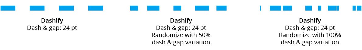
As per the native Stroke panel, specifies the length of the dashes and gaps. Supports up to five pairs of values, (compared to three for the native panel). When using zero as a gap length, the path will still be broken into dashes; each will touch its neighbours. Zero can be useful as a dash length when combined with round end caps: it produces circular dots.
6. Randomize
Allows randomization of the lengths of the dashes and/or the gaps. Randomization is not available when Align Dashes to Corners and Path Ends is enabled.
7. Distribution Curves
Specifies either a linear distribution in random values (all values in the range are equally likely to be chosen) or a Gaussian distribution (central values in the range are more likely to be chosen).
8. Seed
Each random seed number leads to a different sequence of random values. Clicking the button picks a new seed, thereby changing the look of the artwork. To view or specify the seed number directly, Option/Alt-click the button. This lets you recreate a previously-generated look.
9. Dash Length Variation
Specifies the random variation in the length of each dash. For example, if a dash’s length is set to 20 pt, then a variation value of 25% would produce lengths that vary by as much as 20 pt × 25% = 5 pt, that is, between 15 pt and 20 pt; a variation value of 90% would produce lengths between 2 pt and 20 pt.
10. Gap Length Variation
As per Dash Length Variation, but for gaps.
AG Utilities Live Effects - Dashify Randomization
11. Preview
As with all live effects, when enabled, changing a parameter will immediately update the artwork while the dialog is still open.
12. Help Button
Opens the help documentation in the Astute Manager. If this does not automatically appear, please ensure your Astute Manager is running first.
Extend Path Live Effect
Extend Path is an Astute Graphics live effect for open paths that allows them to be extended (lengthened) or shortened. Extension can be made using four different methods, and randomization options are available.
As with most live effects, Extend Path appears in the main menu, under Effect > AG Utilities. It can also be applied directly from the Appearance panel using the “Add New Effect” button at the bottom of the panel.
Extend Path Parameters Dialog
After applying the live effect using the menu item (or when clicking on the existing effect in the Appearance panel to edit it), the parameters dialog will appear:
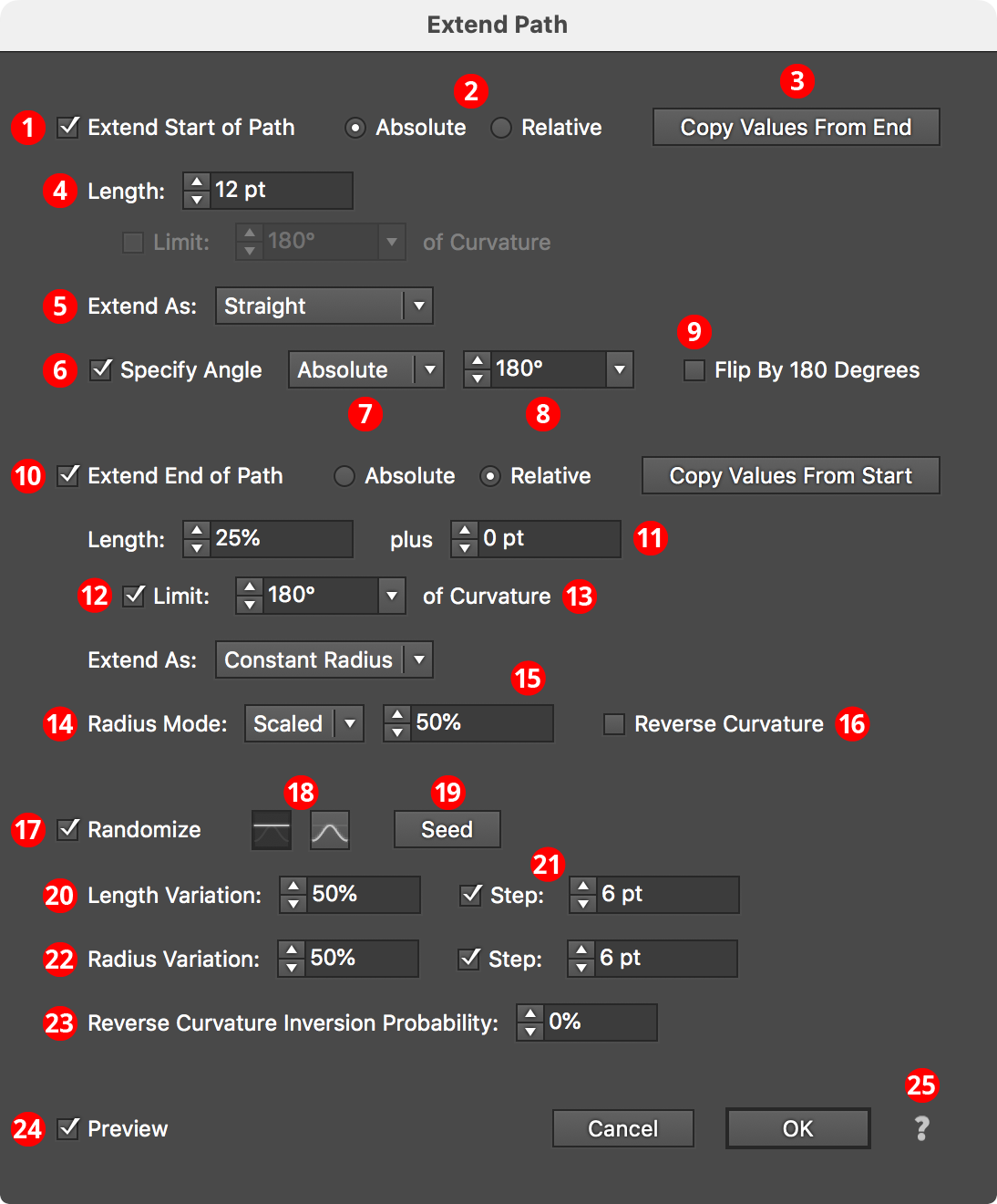
Extend Path Parameters Dialog
1. Extend Start of Path
Each end of the open path can be independently affected. The top section of the dialog pertains to the start of the path.
2. Absolute/Relative
Specifies whether the extension length is an absolutely-specified value (for example, 24 pt) or a value relative to the path length (for example, 50%, which would make the path 1.5 times as long as it was originally).
3. Copy Value button
Allows you to pick up all the parameters from the section of the dialog for the opposite end of the path, in cases where both ends of the path must be extended in the same manner.
4. Length
The amount that the path will be extended or shortened. In Relative mode, the value is interpreted as a percentage of the original path length. Negative values will result in the path being shortened instead of extended.
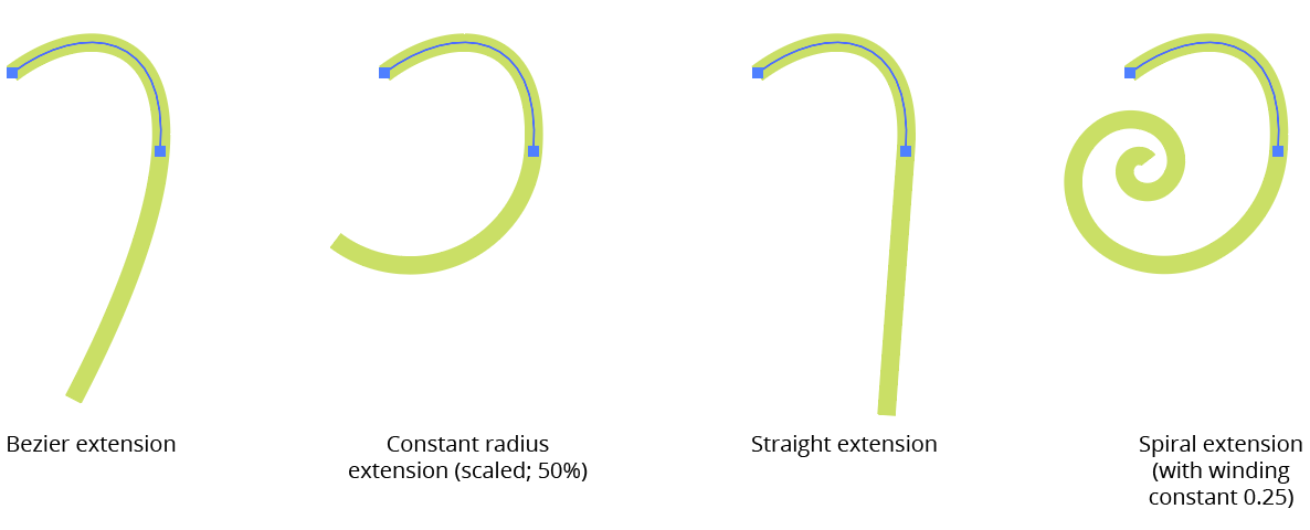
5. Extend As
The type of extension (ignored when shortening a path).
Bezier Extension
In Bezier extension mode, no additional anchor points are added to the path. Instead, the cubic bezier curve that comprises the path segment being extended is simply expanded. Due to the mathematics of cubic beziers, this may lead to situations where the curve turns in unexpected directions or even reverses direction at a cusp point if the original bezier had only a single handle.
Constant Radius Extension
In Constant Radius extension mode, the path is continued as a circular arc of constant radius. The radius value itself depends on which radius mode is active (see Radius Mode).
Straight Extension
In Straight extension mode (the default), the path is continued as a simple straight line.
Spiral Extension
In Spiral extension mode, the path is continued as a logarithmic spiral with the specified winding constant. Lower winding constants make the spiral’s radii become smaller more quickly.
AG Utilities Live Effects - Path Extension Types
6. Specify Angle
Applicable with Straight extensions only; when enabled, the straight extension of the path will not be made at the original angle of the end of the path, but at the specified angle.
7. Specify Angle Mode
When specifying the straight extension angle, you can choose between an absolute angle or an angle that represents the change in angle (“Difference”) between the end of the path and the extension.
8. Specify Angle Value
The final angle, either as an absolute value or as a difference in angles.
9. Flip by 180 Degrees
The final angle is flipped by 180 degrees.
10. Extend End of Path
All controls are identical to the “Start of Path” section, but control the other end of the path.
11. Plus Value
For Relative mode extensions, allows an absolute value to be added to the relative value.
12. Limit Curvature
For Constant Radius and Spiral extensions, limits the length of the extension based on the amount of path bend.
13. Limit Curvature Value
The maximum amount of path bend (in degrees), regardless of length.
14. Radius Mode
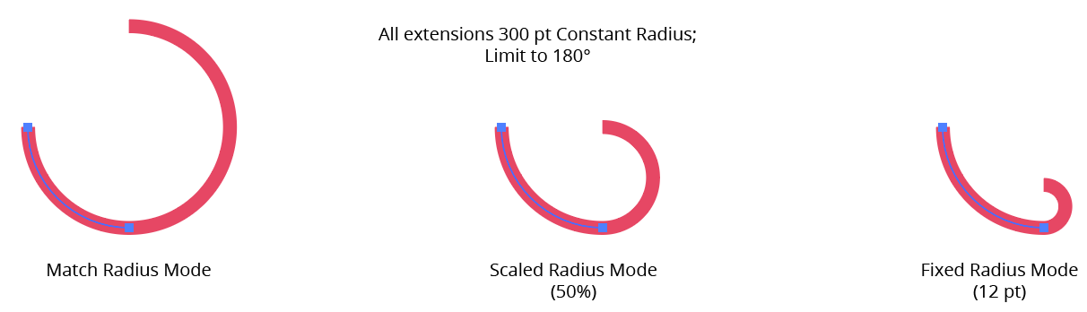
For Constant Radius and Spiral extensions, one of the following: Match Radius Mode (the radius value will match the existing radius at the end of the path); Scaled Radius Mode (the radius value will be taken from the existing radius multiplied by the scale value); or Fixed Radius Mode (the radius value will be equal to the specified fixed value).
AG Utilities Live Effects - Extend Path Radius Modes
15. Radius Value
For Scaled and Fixed modes, the scale factor or fixed value.
16. Reverse Curvature
Normally the curvature of the extension is in the same direction as the existing path; Reverse Curvature makes the extension curve in the opposite direction.
17. Randomize
Allows randomization of several parameters, including length, radius, and the probability of reverse curvature. Randomization is most useful when applying the Extend Path effect to a group of many paths, or in an effect stack in which a previous effect breaks a single path into multiple pieces, like Dashify.
18. Distribution Curves
Specifies either a linear distribution in random values (all values in the range are equally likely to be chosen) or a Gaussian distribution (central values in the range are more likely to be chosen).
19. Seed
Each random seed number leads to a different sequence of random values. Clicking the button picks a new seed, thereby changing the look of the artwork. To view or specify the seed number directly, Option/Alt-click the button. This lets you recreate a previously-generated look.
20. Length Variation
Specifies the random variation in the length of the extension. For example, if the length is set to 20 pt, then a variation value of 25% would produce lengths that vary by as much as 20 pt × 25% = 5 pt, that is, between 15 pt and 20 pt; a variation value of 90% would produce lengths between 2 pt and 20 pt.
21. Length Step
Constrains each final extension length (after randomization) to multiples of the specified step value while still remaining in the original range. For example, if the extension length is set to 24 pt with a random variation of 50%, then normally values of 12 to 24 pt would be produced. But enabling Step with a value of 5 pt would result in only values of 15 pt and 20 pt.
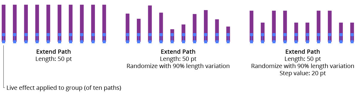
AG Utilities Live Effects - Extend Path Randomization
22. Radius Variation
For Constant Radius and Spiral extensions, similar to Length Variation but affects the final radius value.
23. Reverse Curvature Inversion Probability
For Constant Radius and Spiral extensions, specifies the probability that the reverse curvature setting (when enabled) will be inverted to the opposite value.
24. Preview
As with all live effects, when enabled, changing a parameter will immediately update the artwork while the dialog is still open.
25. Help Button
Opens the help documentation in the Astute Manager. If this does not automatically appear, please ensure your Astute Manager is running first.
Make Compound Path Live Effect
Make Compound Path is an Astute Graphics live effect with one simple function: to turn multiple paths into a single compound path. It has no parameters.
As with most live effects, Make Compound Path appears in the main menu, under Effect > AG Utilities. It can also be applied directly from the Appearance panel using the “Add New Effect” button at the bottom of the panel.
The Make Compound Path effect is mainly useful when followed by a native PathFinder effect such as “Intersect”. For example, if a group of four circles has an “Intersect” effect applied, normally nothing happens. But if it is preceded by Make Compound Path, then the Boolean operation works as expected:
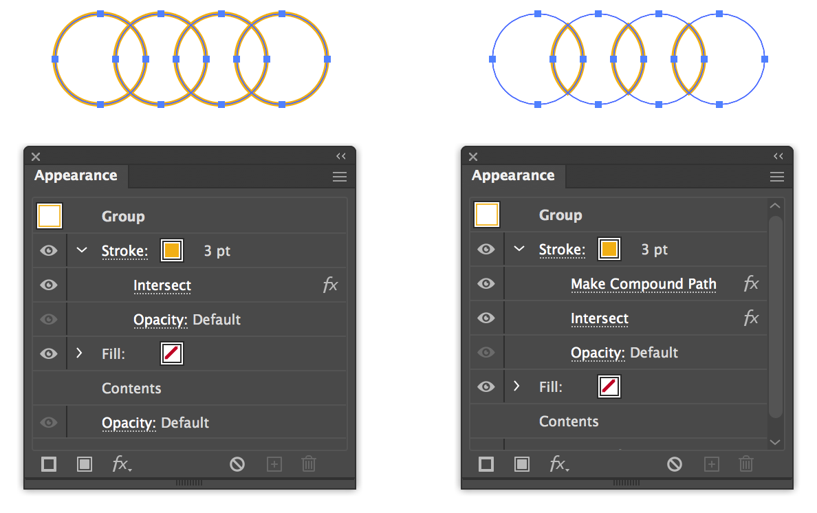
AG Utilities Live Effects - Make Compound Path
Make Shape Live Effect
Make Shape is an Astute Graphics live effect that creates paths which are basic geometric shapes from the artwork to which it is applied. In its basic form it is similar to the native “Convert to Shape” effect, but it includes many more parameters and options, such as the ability to place the shapes above or under the original artwork, the ability to change the alignment, and angle of the shape, and the ability to place multiple copies of shapes along paths. Randomization options are also included.
As with most live effects, Make Shape appears in the main menu, under Effect > AG Utilities. It can also be applied directly from the Appearance panel using the “Add New Effect” button at the bottom of the panel.
Make Shape Parameters Dialog
After applying the live effect using the menu item (or when clicking on the existing effect in the Appearance panel to edit it), the parameters dialog will appear:
Make Shape Parameters Dialog
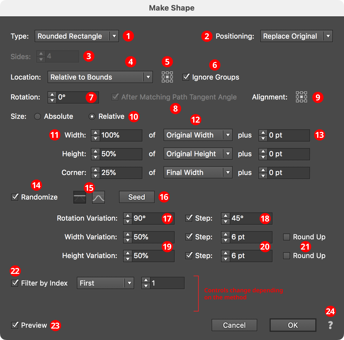
1. Shape Type
The type of shape to create, from among: Arc, Circle, Ellipse, Half-Circle, Line, Polygon, Rectangle, Rounded Rectangle, Square, Star, and Triangle. Depending on the type of shape selected, other parameter controls in the dialog may be hidden or changed.
2. Positioning
The position of the shape relative to the original artwork. It can replace the original (the default), or go above or below it.
3. Sides
Some of the shape types (Arc, Circle, Ellipse, Half-Circle, Polygon, and Star) allow the number of sides (anchor points for rounded shapes; points for stars) to be specified, from 3 to 1000. For Stars, an additional control will appear that lets you force the star to be “Regular” (this locks the ratio of its inner diameter to its outer diameter).
4. Location
Where to place the shape(s). The default, similar to the native “Convert to Shape” effect, is relative to the bounding box of the original artwork (note that Make Shape uses the outlines of live text to directly determine its bounding box). Other options (each will add parameter-specific controls alongside the popup menu) include:
Along Path (Once)

AG Utilities Live Effects - Make Shape Along Path Once
The shape is placed once along each path at the specified path length fraction (0 to 100%), where 0% indicates the start of the path and 100% indicates the end of the path; for closed paths, 0% and 100% refer to the same spot.
Along Path (By Count)

AG Utilities Live Effects - Make Shape Along Path by Count
The shape is placed the specified number of times along each path, equally spaced. For open paths, a shape is placed at each end except when Center is enabled: then the endpoints do not receive shapes and instead the shapes are placed along the interior of the path such that equal spacing would be maintained if multiple copies of the path were placed end-to-end. For closed paths, Center shifts the shapes such that they appear centered between the spots where they would be placed if Center were not enabled.
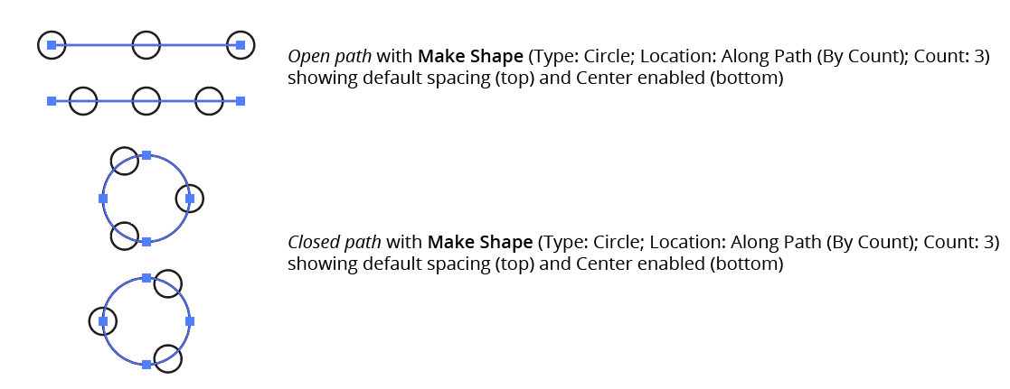
AG Utilities Live Effects - Make Shape Along Path by Count Center
Along Path (By Distance)

AG Utilities Live Effects - Make Shape Along Path by Distance
Shapes are placed along each path, starting at the first anchor point, with the specified distance between shapes. When Adjust is enabled, the spacing is modified in one of two different ways. In Center mode, the shapes are moved to be centered within the path. In Fit mode, the distance value is changed to the closest value which produces an integral number of shapes along the path.
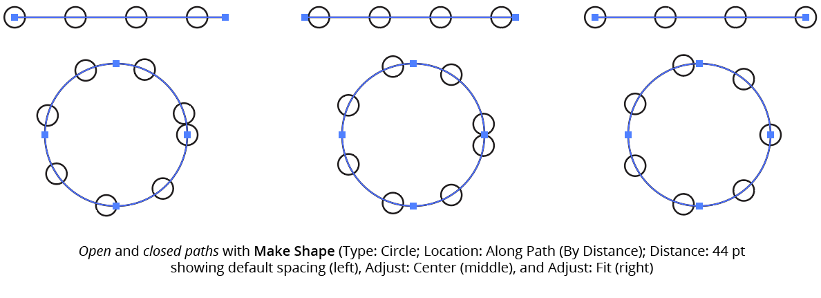
AG Utilities Live Effects - Make Shape Along Path by Distance Example
If the distance exceeds the path length, then no shapes are created unless Adjust is enabled.
Along Each Segment

AG Utilities Live Effects - Make Shape Along Each Segment
Shapes are placed along segments of each path at the specified length fraction (0 to 100%), where 0% indicates the start of the segment and 100% indicates the end of the segment. By default, all segments are included, but this can be changed to First, Last, Even Only, Odd Only, Curved Only, or Straight Only to affect only a subset of the segments.
At Anchor Points

AG Utilities Live Effects - Make Shape at Anchor Points
Shapes are placed at the positions of the anchor points of each path. By default, all anchor points are included, but this can be changed to First, Last, Even Only, Odd Only, Corner Only, or Smooth Only to affect only a subset of the anchor points.
5. Nine-block Control
When using a Location of Relative to Bounds, allows the picking of one of the nine standard positions (upper-left, upper-center, etc.) to which the shape can be oriented relative to the bounding box.
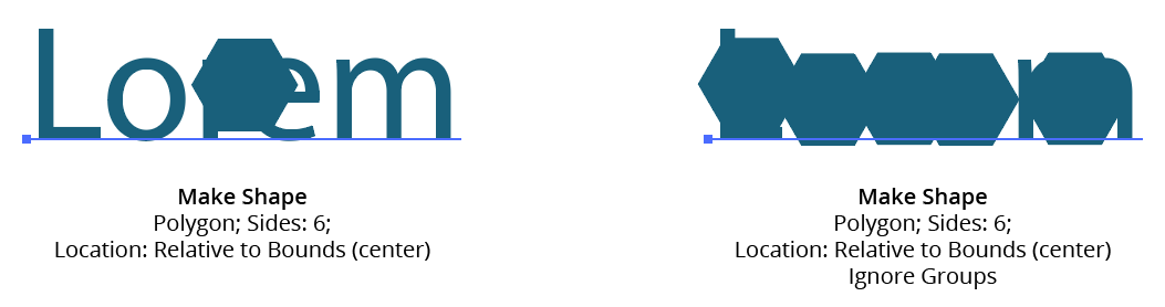
6. Ignore Groups
When using a Location of Relative to Bounds, when enabled, bounds are calculated separately for each member of any group in the original art (including groups created internally by the live effect mechanism), thereby resulting in multiple shapes if the group has more than one object (such as live text).
AG Utilities Live Effects - Make Shape Ignore Groups
7. Rotation
Specifies the rotation of the shape. This rotation value may be in addition to path tangent-matching rotation (see below).
8. After Matching Path Tangent Angle
This option is available when the location is set to anything other than Relative to Bounds. When enabled, the shape is first rotated to match the tangent angle at its spot along the path, and then any additional rotation specified by the rotation option is added to that value. Angles at corner points are determined by averaging the angles on either side of the point.
9. Alignment
Specifies the alignment of the shape to its nominal center point. This alignment is calculated with the shape in an unrotated state and any rotation is then carried out around the alignment point.
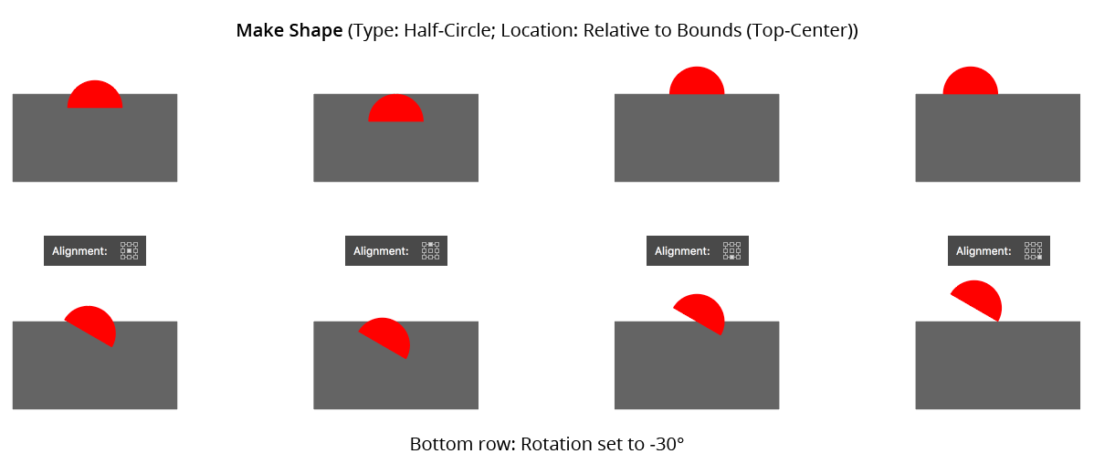
AG Utilities Live Effects - Make Shape Alignment
10. Size
When set to Absolute, the dimensions of the shape are set directly. When Relative, each dimension is based on another dimension, specified using the menu.
11. Dimensional Values
Sets the dimension(s) of the shape (shape types of Arc, Circle, Half-Circle, Line, Polygon, and Square have only a single dimension; Rounded Rectangle has three dimensions).
12. Dimensional Relative
For size Relative, specifies what the dimension is based on. For example, a circle’s diameter can be set to 50% of the original width of the art. For shape types with two or more dimensions, one dimension can be based on the other to determine its aspect ratio (for example, an ellipse’s width can be set to 200% of its height).
13. Plus Value
For size mode Relative, specifies an additional value that is added to the relatively-derived dimension, essentially giving it a minimum value.
14. Randomize
Allows randomization of the rotation and dimensions of the shapes.
15. Distribution Curves
Specifies either a linear distribution in random values (all values in the range are equally likely to be chosen) or a Gaussian distribution (central values in the range are more likely to be chosen).
16. Seed
Each random seed number leads to a different sequence of random values. Clicking the button picks a new seed, thereby changing the look of the artwork. To view or specify the seed number directly, Option/Alt-click the button. This lets you recreate a previously-generated look.
17. Rotation Variation
Specifies the maximum amount of variation in the final rotation of the shapes (in either clockwise or counter-clockwise directions), in degrees. For example, if the rotation value is set to 90° and the variation is set to 15°, possible values would be between 75 and 105°.
18. Rotation Step
Constrains each final rotation value (after randomization) to multiples of the specified step value while still remaining in the original range. In the example above, where possible values range continuously between 75 and 105°, setting the step value to 10° would instead only result in values of 80°, 90° or 100°.
19. Dimensional Variations
Specifies the random variation in the first dimension of the shape. For example, using a Line shape, if the length is set to 20 pt, then a variation value of 25% would produce lengths that vary by as much as 20 pt × 25% = 5 pt, that is, between 15 pt and 20 pt; a variation value of 90% would produce lengths between 2 pt and 20 pt.
20. Dimensional Steps
Constrains each final shape dimension (after randomization) to multiples of the specified step value while still remaining in the original range. For example, using a Line shape, if the length is set to 24 pt with a random variation of 50%, then normally values of 12 to 24 pt would be produced. But enabling Step with a value of 5 pt would result in only values of 15 pt and 20 pt.
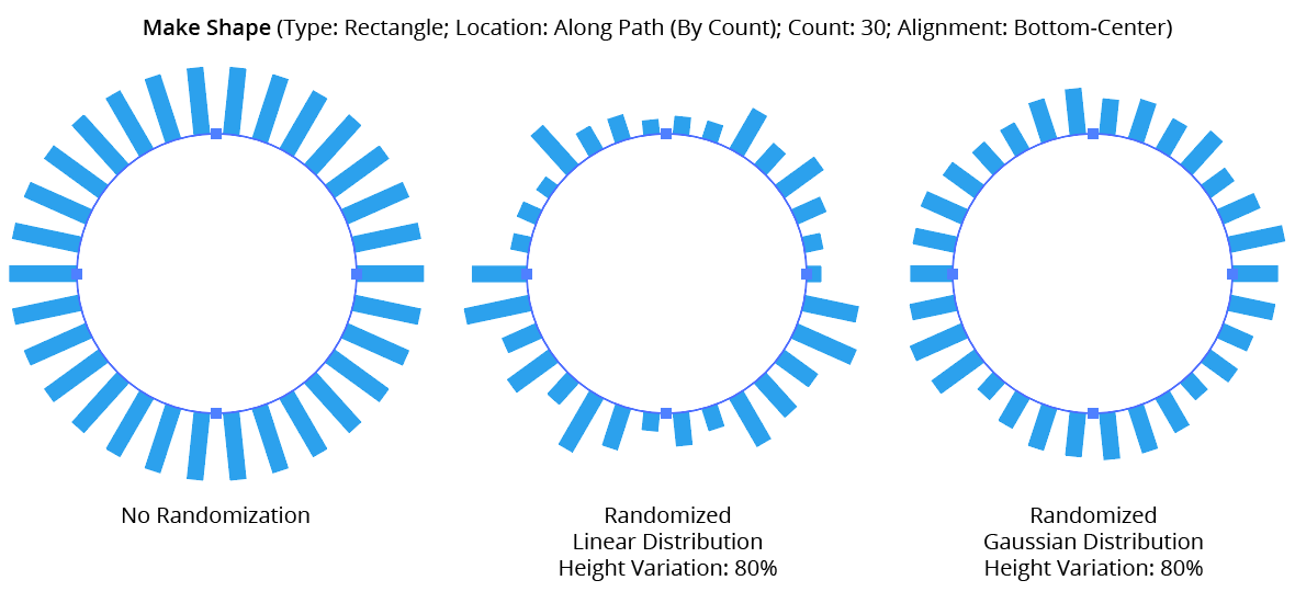
AG Utilities Live Effects - Make Shape Randomization
21. Round Up
When constraining a dimensional value to steps, enabling this setting ensures that the stepped (quantized) value is always higher then the non-quantized value. For example, suppose Make Shape were used to place a rectangle behind live text, but the rectangle needed to be a multiple of 20 pt wide. Without Round Up, the rectangle would sometimes become narrower than the text:
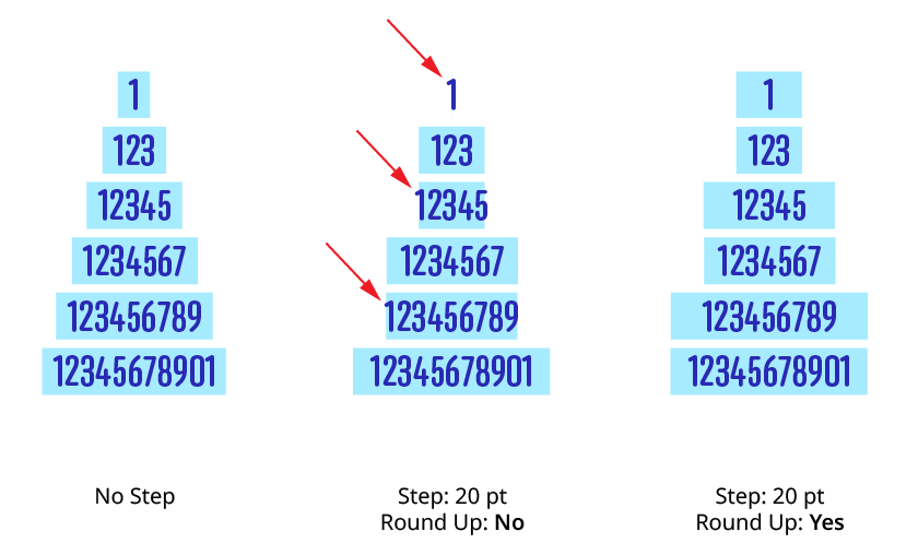
Make Shape Step Round Up
22. Filter By Index
When enabled (and the effect has been applied to a group or is inside a live effect stack which has internally created multiple objects), each art object’s index is used to determine whether it should have a shape made from it, using one of seven different methods. The index is simply an integer sequentially assigned to each object in the order it is encountered, starting with zero for the first object. Generally, the index increases going downwards in the stacking order; however, other live effects present in the appearance stack may change this order, sometimes randomly (such as PathFinder effects). Additionally, objects may be created which are invisible in the final appearance if they have no fill or stroke. The available By Index methods are as follows:
a. First: Only the first n objects are affected, where n is the specified value.

Make Shape Filter By Index - First Controls
b. Last: Only the last n objects are affected, where n is the specified value.

Make Shape Filter By Index - Last Controls
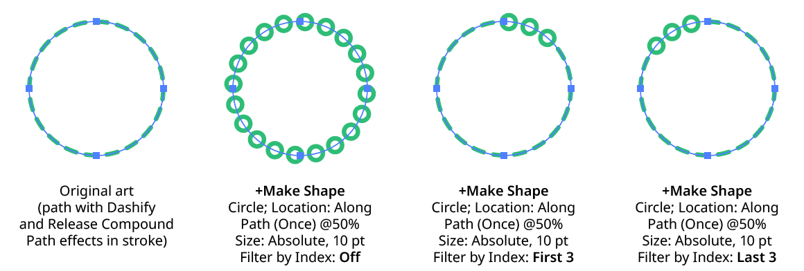
Make Shape Filter By Index - First, Last
c. First or Last: Only the first and last objects are affected.
d. Odd: Only objects with an odd index (1, 3, 5, 7...) are affected.
e. Even: Only objects with an even index (0, 2, 4, 6...) are affected.
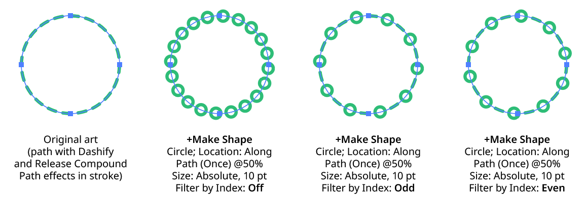
Make Shape Filter By Index - Odd, Even
f. Pattern: Creates a repeating pattern of matching indices based on the three pattern parameters.
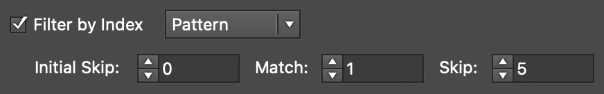
Make Shape Filter By Index - Pattern Controls
Initial Skip specifies the number of indices to skip over at the start (art with these indices will not be affected). Then, Match specified the number of indices that will match and therefore be affected. Finally, Skip specifies the number of indices to skip over following the matching indices. When the total of the values in the three parameters is less than the number of eligible art objects, the pattern repeats, using the Match and Skip values in alternation.
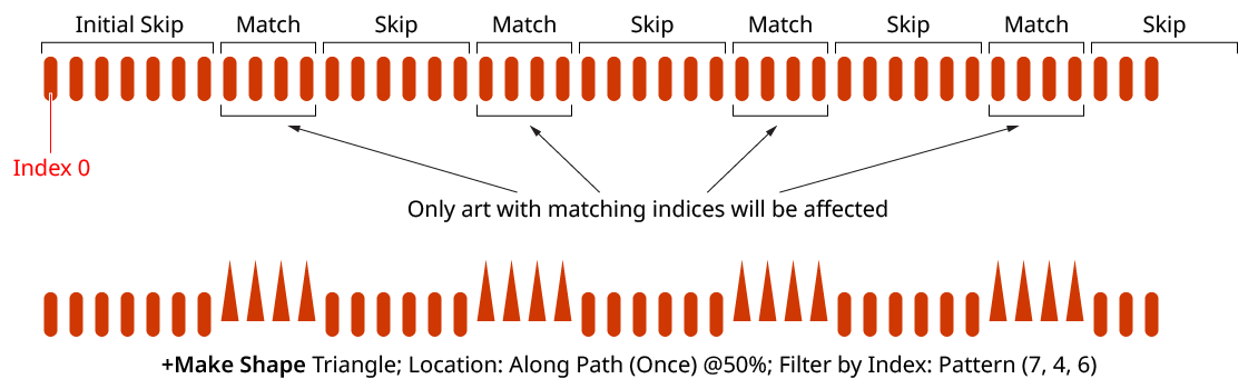
Make Shape Filter By Index - Pattern
g. Randomly: Each art object has the specified random chance (from 0% to 100%) of being affected. The parameter has an independent seed value. Just as with move/rotate/scale seed values, clicking the button picks a new seed, thereby changing the look of the artwork. To view or specify the seed number directly,
Option/Alt-clickthe button. This lets you recreate a previously-generated look.

Make Shape Filter By Index - Randomly Controls
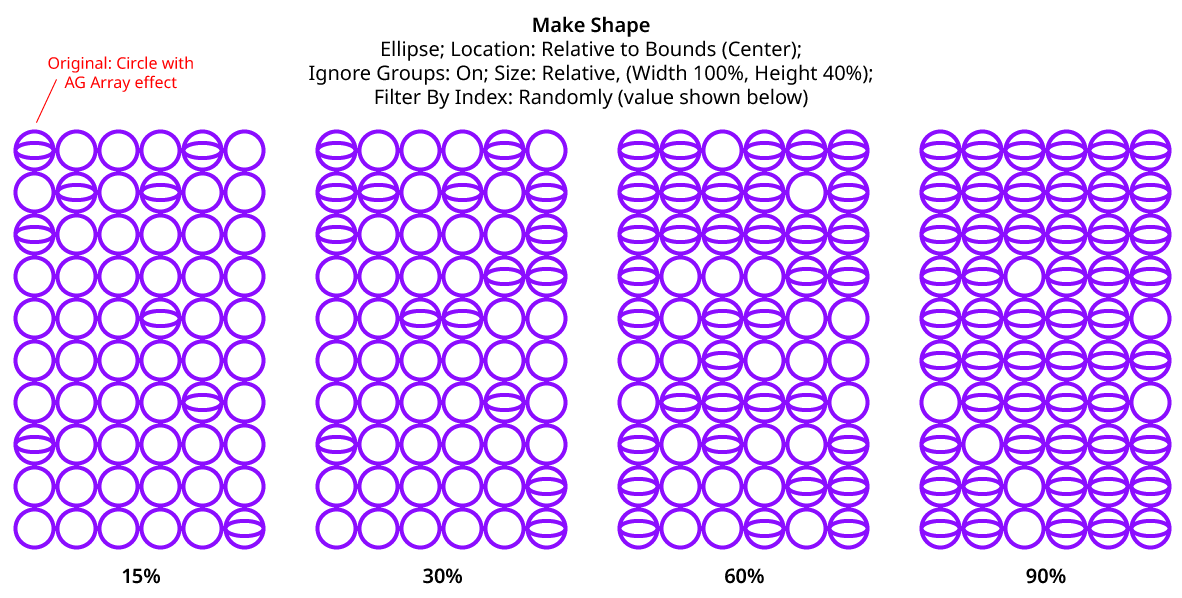
Make Shape Filter By Index - Randomly
23. Preview
As with all live effects, when enabled, changing a parameter will immediately update the artwork while the dialog is still open.
24. Help Button
pens the help documentation in the Astute Manager. If this does not automatically appear, please ensure your Astute Manager is running first.
Path Removal Live Effect
Path Removal is an Astute Graphics live effect that removes paths from the object it is applied to, based on criteria such as path length, type (open/closed), or index. It is most useful when applied to a group of many paths, or is preceded by another live effect which breaks one path into many, such as Astute’s Dashify or Split Path to Segments.
As with most live effects, Path Removal appears in the main menu, under Effect > AG Utilities. It can also be applied directly from the Appearance panel using the “Add New Effect” button at the bottom of the panel.
Path Removal Parameters Dialog
After applying the live effect using the menu item (or when clicking on the existing effect in the Appearance panel to edit it), the parameters dialog will appear:

Path Removal Parameters Dialog
1. Criteria Popup
By default, paths will be removed only if they match all of the enabled options (the first six checkboxes below). However you can change this to When They Match Any Enabled Options, Unless They Match All Enabled Options, or Unless They Match Any Enabled Options.
2. Point Count
Paths match when they have an anchor point count from the minimum to the maximum values specified. The defaults are both 1, meaning paths will match if they are single points. When compound paths are treated as a whole, the anchor point count is the sum of all the anchor points in all subpaths.
3. Length
Paths match when they have a length from the minimum to the maximum values specified. When compound paths are treated as a whole, the length is the sum of the lengths of all subpaths.
4. Type
Paths match when their type is the same as specified. When compound paths are treated as a whole, they match if all of the subpaths match.
5. Subpaths of a Compound Path
Paths match as specified.
6. Segments With Handles
When set to Yes, paths match if any of their segments have handles; when set to No, paths match if none of their segments have handles.
7. Index
Paths match if their index matches the specified indices. Paths are assigned indices starting at zero, increasing in the order in which they are encountered within the live effect. The default type of index match is Odd, i.e. 1, 3, 5, 7, etc. Other options are First, Last, First or Last, Even, and Pattern. Pattern type creates a repeating pattern of matching indices based on the three subsequent parameters.
8. Initial Skip
For Pattern index matching, the initial number of indices to skip over.
9. Match
For Pattern index matching, the number of indices to match after skipping some.
10. Skip
For Pattern index matching, the number of indices to skip over after matching some.
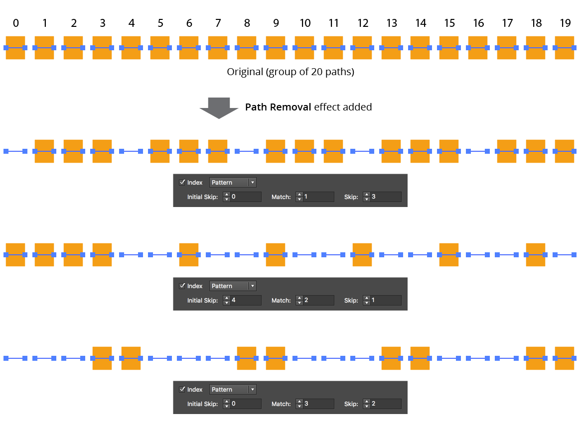
AG Utilities Live Effects - Path Removal Pattern
11. Randomize
Allows randomization of the removal.
12. Seed
Each random seed number leads to a different sequence of random values. Clicking the button picks a new seed, thereby changing the look of the artwork. To view or specify the seed number directly, Option/Alt-click the button. This lets you recreate a previously-generated look.
13. Retention Probability
The probability that a path that would normally be removed under the previous criteria will instead be retained. This value can be fixed (the default) or based on the index.
14. Retention Probability Value
For Fixed probability, the fixed value that applies to all removed paths. When the probability is set to Indexed, it consists of a starting probability value and an ending probability value, which linearly changes based on the index of the path.
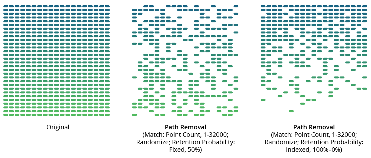
AG Utilities Live Effects - Path Removal Randomization Retention
15. Keep Same Geometry Paths Together
When the Path Removal effect is positioned under an artwork’s strokes and fills in the Appearance panel, the stroked and filled paths are passed to it separately, and would therefore normally be randomly affected independently, leading to some paths being stroked but not filled and vice versa. Sometimes this can be solved by simply moving the Path Removal effect above them in the Appearance panel, but depending on the other effects that are present, this may not always be possible. In that case, enabling this setting allows paths with the exact same underlying geometry (such as fills and strokes of the same path) to be retained or removed in a unified manner.
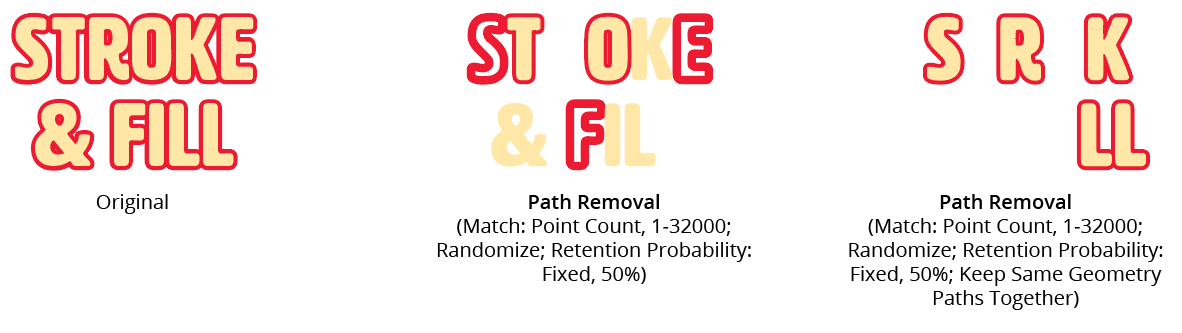
AG Utilities Live Effects - Path Removal Keep Same Geometry Together
16. Treat Compound Paths As a Whole
Normally each subpath of a compound path is examined for possible removal independently. When this setting is enabled, compound paths are either removed in their entirety or retained in their entirety. Some of the match parameters are interpreted slightly differently (for example, Point Count is interpreted to mean the total number of anchor points in all of the compound path’s subpaths).
17. Preview
As with all live effects, when enabled, changing a parameter will immediately update the artwork while the dialog is still open.
18. Help Button
Opens the help documentation in the Astute Manager. If this does not automatically appear, please ensure your Astute Manager is running first.
Path Visualizer Live Effect
Path Visualizer is an Astute Graphics live effect that provides the visualization of anchor points, handles, and redundant points on a path or live text by rendering them as art elements. These art elements remain visible even if the path is not selected. Path Visualizer can be useful when evaluating various fonts (no need to create outlines), and when building large effect stacks; by temporarily inserting it at a certain location in the stack (and hiding effects below it), the state of the path(s) at that point in the effect chain can be visualized without having to expand the effect.
As with most live effects, Path Visualizer appears in the main menu, under Effect > AG Utilities. It can also be applied directly from the Appearance panel using the “Add New Effect” button at the bottom of the panel.
Path Visualizer Parameters Dialog
After applying the live effect using the menu item (or when clicking on the existing effect in the Appearance panel to edit it), the parameters dialog will appear:

Path Visualizer Parameters Dialog
1. Visualize Anchor Points
Creates a filled square at each anchor point on the path. At default 100% scaling, the squares have a side length of 5 pt.
2. Visualize Handles
Creates a filled circle at each bezier handle on the path. At default 100% scaling, the circles have a diameter of 5 pt.
3. Visualize Handle Lines
Creates a straight line from each handle to its associated anchor point on the path. At default 100% scaling, the lines have a stroke weight of 0.75 pt.
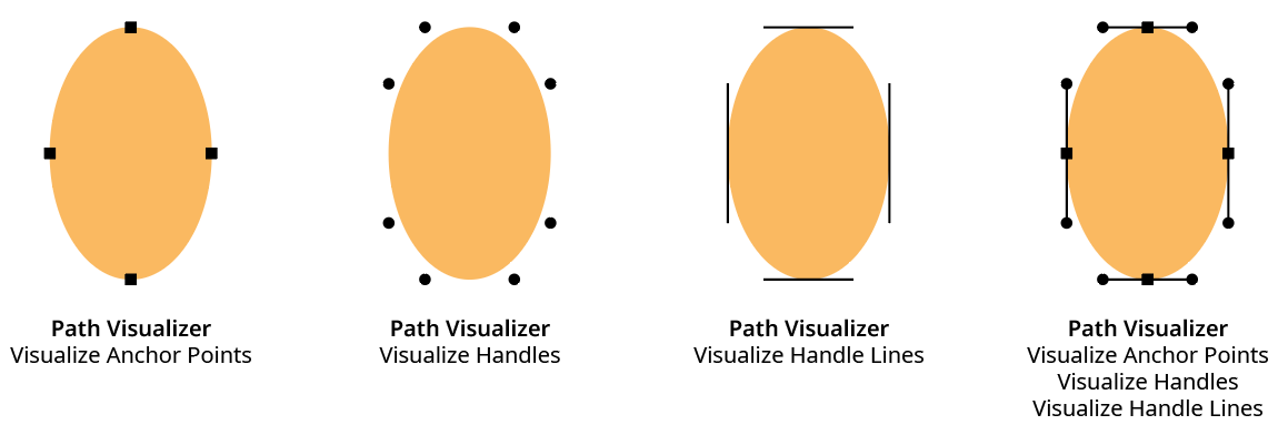
AG Utilities Live Effects - Path Visualizer Example
4. Visualize Redundant Points
Draws a semi-transparent red, triangular shape similar to the Astute Graphics PathScribe tool redundant point indicator over redundant points. A redundant point, also known as a doubled point, is defined as the latter of two consecutive anchor points on a path that have exactly the same X and Y coordinates and don’t have handles in the (zero-length) segment between them. They are often created after using the PathFinder functions or after using Object > Path > Outline Stroke, and despite not changing the shape of the path, can cause problems when performing additional functions such as offsetting.
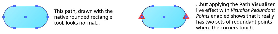
AG Utilities Live Effects - Path Visualizer Redundant Points
5. Include Unpainted Paths
When enabled, paths that have no fill or stroke are included when generating the visualization art. This is generally only necessary when placing the Path Visualizer effect above the fills and strokes in the Appearance panel.
6. Scale
Makes all the visualization art smaller or larger by the specified amount. The annotations that typically show anchor points and handles are independent of the zoom value, but since the live effect visualizations create actual art, they will get larger when the art is zoomed in on. This can make it difficult to see points that are very close to each other, very short handles, etc. The Scale factor can vary from 0.1% to 10000%.
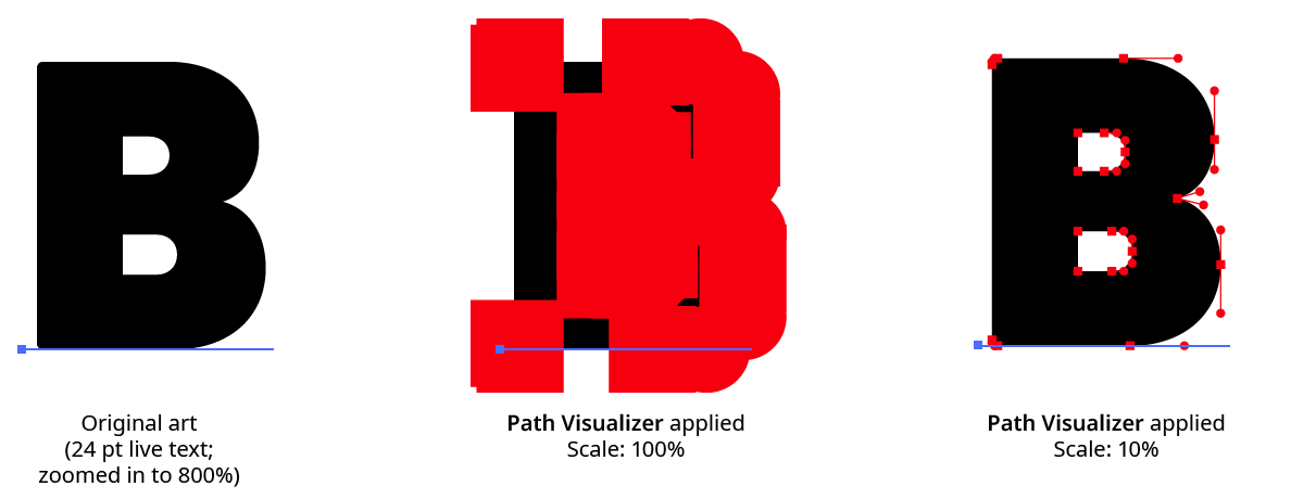
AG Utilities Live Effects - Path Visualizer Scale Example
7. Positioning
The position of the visualization art relative to the original artwork. It can replace the original, go above it (the default), or go below it.
8. Color
The color of the visualization art for anchor points, handles, and handle lines. The default color is black, but it can be changed by clicking on the color chip to bring up the standard color picker.
9. Preview
As with all live effects, when enabled, changing a parameter will immediately update the artwork while the dialog is still open.
10. Help Button
Opens the help documentation in the Astute Manager. If this does not automatically appear, please ensure your Astute Manager is running first.
Point Removal Live Effect
Point Removal is an Astute Graphics live effect that removes anchor points from the paths in the artwork to which it is applied, based on criteria such as their distance from the previous point, the change in path angle at the point, or index. In contrast to the Smart Remove Points live effect, the handles of non-removed points are not adjusted to try to maintain path geometry.
As with most live effects, Point Removal appears in the main menu, under Effect > AG Utilities. It can also be applied directly from the Appearance panel using the “Add New Effect” button at the bottom of the panel.
Point Removal Parameters Dialog
After applying the live effect using the menu item (or when clicking on the existing effect in the Appearance panel to edit it), the parameters dialog will appear:

Point Removal Parameters Dialog
1. Criteria Popup
By default, points will be removed only if they match all of the enabled options (the first four checkboxes below). However you can change this to When They Match Any Enabled Options, Unless They Match All Enabled Options, or Unless They Match Any Enabled Options.
2. Distance From Previous
Points match when their distance (measured along the path) to the previous anchor point is between the minimum and the maximum values specified. The first point on an open path will never be matched.
3. Change In Path Angle
Points match when the change in the tangent angle of the path at the point is between the minimum and maximum values specified. Smooth points (unless malformed) will always have a 0° change in angle. The endpoints of an open path will never be matched.
4. Handles
Points match when their number of handles match the specified value: None, Any, Exactly One, or Exactly Two.
5. Index
Points match if their index matches the specified indices. Points are assigned indices starting at zero, increasing in the order in which they are encountered within the live effect. The default type of index match is Odd, i.e. 1, 3, 5, 7, etc. Other options are First, Last, First or Last, Even, and Pattern. Pattern type creates a repeating pattern of matching indices based on the three subsequent parameters.
6. Initial Skip
For Pattern index matching, the initial number of indices to skip over.
7. Match
For Pattern index matching, the number of indices to match after skipping some.
8. Skip
For Pattern index matching, the number of indices to skip over after matching some.
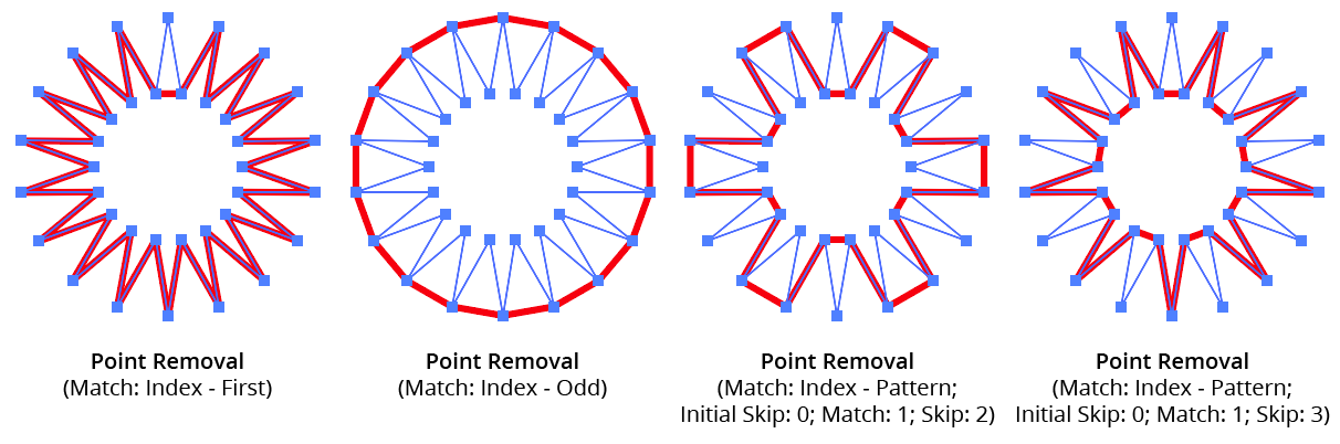
AG Utilities Live Effects - Point Removal Pattern
9. Randomize
Allows randomization of the removal.
10. Seed
Each random seed number leads to a different sequence of random values. Clicking the button picks a new seed, thereby changing the look of the artwork. To view or specify the seed number directly, Option/Alt-click the button. This lets you recreate a previously-generated look.
11. Retention Probability
The probability that a point that would normally be removed under the previous criteria will instead be retained.
12. Keep Same Geometry Paths Together
When the Point Removal effect is positioned under an artwork’s strokes and fills in the Appearance panel, the stroked and filled paths are passed to it separately, and their points would therefore normally be randomly affected independently, leading to some paths having different points removed when Randomize is enabled. Sometimes this can be solved by simply moving the Point Removal effect above them in the Appearance panel, but depending on the other effects that are present, this may not always be possible. In that case, enabling this setting allows paths with the exact same underlying geometry (such as fills and strokes of the same path) have the same points removed or retained.
13. Preview
As with all live effects, when enabled, changing a parameter will immediately update the artwork while the dialog is still open.
14. Help Button
Opens the help documentation in the Astute Manager. If this does not automatically appear, please ensure your Astute Manager is running first.
Release Compound Path Live Effect
Release Compound Path is an Astute Graphics live effect with one simple function: to break compound paths into their individual subpaths. It has no parameters.
As with most live effects, Release Compound Path appears in the main menu, under Effect > AG Utilities. It can also be applied directly from the Appearance panel using the “Add New Effect” button at the bottom of the panel.
The Release Compound Path effect is useful mainly in cases where subsequent live effects act differently when applied to a compound path than from a group of normal paths. For example, applying an Astute Graphics Dashify live effect to a path (which breaks it into a compound path of many subpaths representing the dashes) and subsequently applying a native “Roughen” effect produces dashes that all have the same roughened profile. But if Release Compound Path is added after the Dashify, then each dash receives a different random roughened profile:
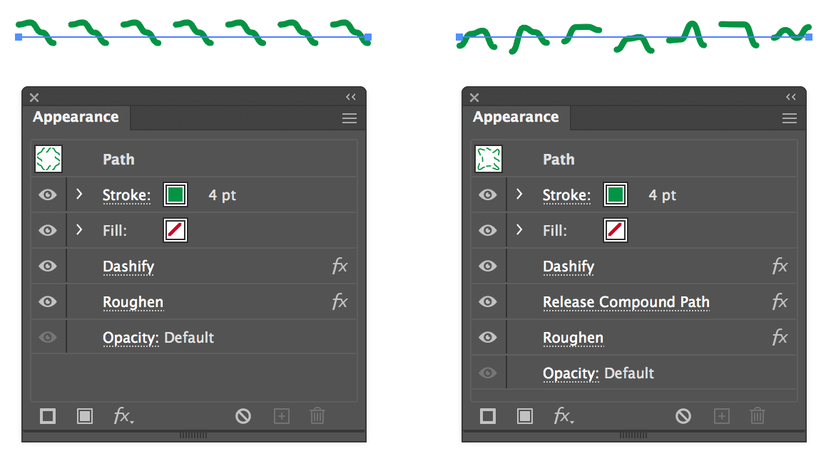
AG Utilities Live Effects - Release Compound Path Example
Retract Handles Live Effect
Retract Handles is an Astute Graphics live effect with one simple function: to retract (remove) the handles of the anchor points in the original art’s paths. An option allows only handles that are shorter than a specified amount to be retracted.
As with most live effects, Retract Handles appears in the main menu, under Effect > AG Utilities. It can also be applied directly from the Appearance panel using the “Add New Effect” button at the bottom of the panel.
Retract Handles Parameters Dialog
After applying the live effect using the menu item (or when clicking on the existing effect in the Appearance panel to edit it), the parameters dialog will appear:
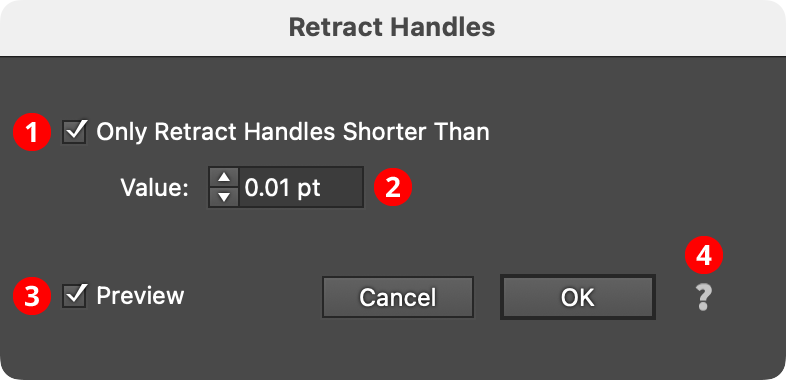
Retract Handles Parameters Dialog
1. Only Retract Handles Shorter Than
When enabled, only the handles in the artwork which are shorter than the specified value are retracted. This can be useful for removing very tiny handles that are generated by a previous live effect in the Appearance stack, such as an Outline Path or PathFinder effect, from keeping subsequent effects, such as AG Corners, from working properly.
2. Value
The length value above which handles will be preserved.
When its Only Retract Handles Shorter Than preference is turned off (the default), the Retract Handles effect ensures that all segments in the paths to which it is applied become straight:
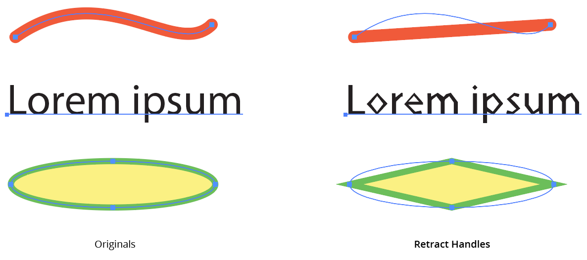
AG Utilities Live Effects - Retract Handles Live Effect
Reverse Path Direction Live Effect
Reverse Path Direction is an Astute Graphics live effect with one simple function: to reverse the directions of all paths. It has no parameters.
As with most live effects, Reverse Path Direction appears in the main menu, under Effect > AG Utilities. It can also be applied directly from the Appearance panel using the “Add New Effect” button at the bottom of the panel.
For paths that are not subsequently brushed, have arrowheads, or are affected by another live effect that depends on path direction (such as Make Shape), Reverse Path Direction will generally not show any visible changes.
Segment Removal Live Effect
Segment Removal is an Astute Graphics live effect that removes segments from the paths in the artwork to which it is applied, based on criteria such as their length, handle status, or index. When segments are removed, the path is split into multiple paths (unless the segments are contiguous in a closed path, in which case the path becomes an open path).
As with most live effects, Segment Removal appears in the main menu, under Effect > AG Utilities. It can also be applied directly from the Appearance panel using the “Add New Effect” button at the bottom of the panel.
Segment Removal Parameters Dialog
After applying the live effect using the menu item (or when clicking on the existing effect in the Appearance panel to edit it), the parameters dialog will appear:

Segment Removal Parameters Dialog
1. Criteria Popup
By default, segments will be removed only if they match all of the enabled options (the first four checkboxes below). However you can change this to When They Match Any Enabled Options, Unless They Match All Enabled Options, or Unless They Match Any Enabled Options.
2. Length
Segments match when they have a length (as measured along the path) from the minimum to the maximum values specified.
3. At Least One Handle
When set to Yes, segments match if they have one or two handles; when set to No, segments match if they have no handles (thus are straight).
4. Index
Segments match if their index matches the specified indices. Segments are assigned indices starting at zero, increasing in the order in which they are encountered within the live effect across multiple paths or subpaths. The default type of index match is Odd, i.e. 1, 3, 5, 7, etc. Other options are First, Last, First or Last, Even, and Pattern. Pattern type creates a repeating pattern of matching indices based on the three subsequent parameters.
5. Initial Skip
For Pattern index matching, the initial number of indices to skip over.
6. Match
For Pattern index matching, the number of indices to match after skipping some.
7. Skip
For Pattern index matching, the number of indices to skip over after matching some.
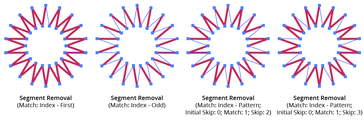
AG Utilities Live Effects - Segment Removal Pattern
8. Randomize
Allows randomization of the removal.
9. Seed
Each random seed number leads to a different sequence of random values. Clicking the button picks a new seed, thereby changing the look of the artwork. To view or specify the seed number directly, Option/Alt-click the button. This lets you recreate a previously-generated look.
10. Retention Probability
The probability that a segment that would normally be removed under the previous criteria will instead be retained.
11. Keep Same Geometry Paths Together
When the Segment Removal effect is positioned under an artwork’s strokes and fills in the Appearance panel, the stroked and filled paths are passed to it separately, and their segments would therefore normally be randomly affected independently, leading to some paths having different segments removed when Randomize is enabled. Sometimes this can be solved by simply moving the Segment Removal effect above them in the Appearance panel, but depending on the other effects that are present, this may not always be possible. In that case, enabling this setting allows paths with the exact same underlying geometry (such as fills and strokes of the same path) have the same segments removed or retained.
12. Preview
As with all live effects, when enabled, changing a parameter will immediately update the artwork while the dialog is still open.
13. Help Button
Opens the help documentation in the Astute Manager. If this does not automatically appear, please ensure your Astute Manager is running first.
Smart Remove Points Live Effect
Smart Remove Points is an Astute Graphics live effect that removes anchor points from a path (like the Point Removal effect) but while trying to maintain the geometry of the path. This is achieved by adjusting the lengths (but not angles) of the handles on either side of the removed points.
As with most live effects, Smart Remove Points appears in the main menu, under Effect > AG Utilities. It can also be applied directly from the Appearance panel using the “Add New Effect” button at the bottom of the panel.
Smart Remove Points Parameters Dialog
After applying the live effect using the menu item (or when clicking on the existing effect in the Appearance panel to edit it), the parameters dialog will appear:

Smart Remove Points Parameters Dialog
1. Tolerance
Specifies how much the geometry of the path can change when removing a point. The value can range between 0 and 200, with a default of 10. Low values remove fewer points (prioritizing the path’s geometry) while high values remove more points (at the likely cost of some distortion).
2. Protect Sharp Corners
When enabled, corner points along the path where the path angle changes by more than 6° are never removed, regardless of the tolerance setting. This allows simplifying smooth sections of a path by using a large tolerance without having to worry that sharp corners will be lost.
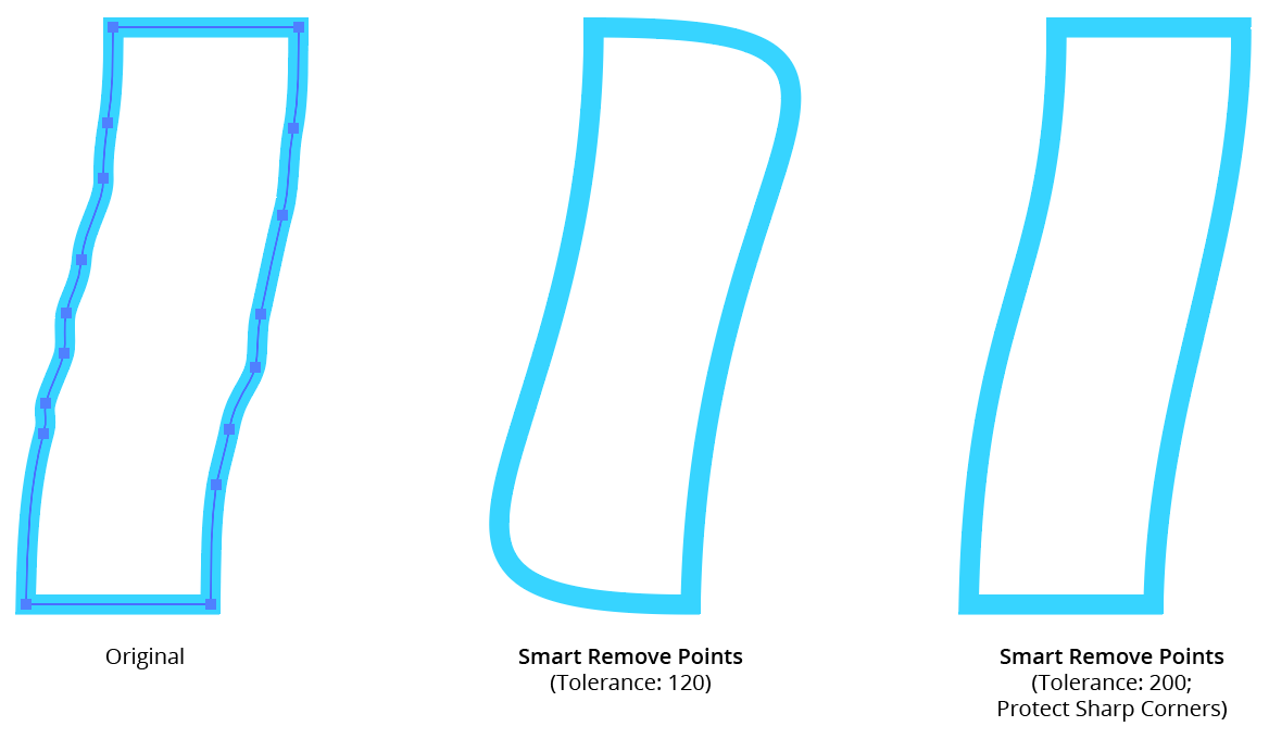
AG Utilities Live Effects - Smart Remove Points Example
3. Preview
As with all live effects, when enabled, changing a parameter will immediately update the artwork while the dialog is still open.
4. Help Button
Opens the help documentation in the Astute Manager. If this does not automatically appear, please ensure your Astute Manager is running first.
Split Path to Segments Live Effect
Split Path to Segments is an Astute Graphics live effect that breaks a path at its anchor points into multiple segments. Paths can be split at corner points, sharp points, or all points.
As with most live effects, Split Path to Segments appears in the main menu, under Effect > AG Utilities. It can also be applied directly from the Appearance panel using the “Add New Effect” button at the bottom of the panel.
Split Path to Segments Parameters Dialog
After applying the live effect using the menu item (or when clicking on the existing effect in the Appearance panel to edit it), the parameters dialog will appear:
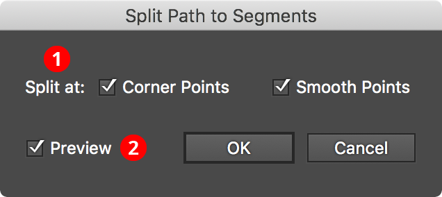
Split Path to Segments Parameters Dialog
1. Split At
Specifies which types of anchor points at which splits should occur: corner, smooth, or both.
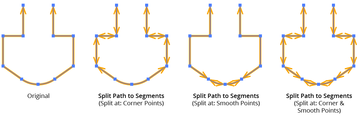
AG Utilities Live Effects - Split Path to Segments Examples
2. Filter By Index
When enabled, each anchor point’s index (starting with zero on each path) is used to determine whether the path will be split at that point. Filter by Index has seven different methods, as follows:
a. First: Each path will be split at the first n points, where n is the specified value.

Split Path to Segments Filter by Index First Controls
b. Last: Each path will be split at the last n points, where n is the specified value.

Split Path to Segments Filter by Index Last Controls
c. First or Last: Only the first and last points will be used as split points.
d. Odd: Only points with an odd index (1, 3, 5, 7...) will be used as split points.
e. Even: Only points with an even index (0, 2, 4, 6...) will be used as split points.
f. Pattern: Creates a repeating pattern of matching indices based on the three pattern parameters.

Split Path to Segments Filter by Index Pattern Controls
Initial Skip specifies the number of indices to skip over at the start (the path will not be split at points with these indices). Then, Match specified the number of indices that will match and therefore cause splits. Finally, Skip specifies the number of indices to skip over following the matching indices. When the total of the values in the three parameters is less than the number of anchor points, the pattern repeats, using the Match and Skip values in alternation.
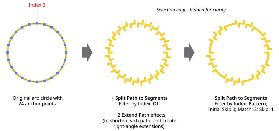
Split Path to Segments Filter by Index - Pattern
g. Randomly: At each anchor point, the path has the specified random chance (from 0% to 100%) of being split. Clicking the Seed button picks a new random seed, thereby changing the look of the artwork. To view or specify the seed number directly,
Option/Alt-clickthe button. This lets you recreate a previously-generated look.

Split Path to Segments Filter by Index Randomly Controls
3. Preview
As with all live effects, when enabled, changing a parameter will immediately update the artwork while the dialog is still open.
3. Help Button
Opens the help documentation in the Astute Manager. If this does not automatically appear, please ensure your Astute Manager is running first.
Stroke Attributes Live Effect
Stroke Attributes is an Astute Graphics live effect that allows changing a path’s stroke parameters (weight, end caps, and corner joins). It also allows forcing a stroke onto a fill-only path, and (optionally) removing that fill.
As with most live effects, Stroke Attributes appears in the main menu, under Effect > AG Utilities. It can also be applied directly from the Appearance panel using the “Add New Effect” button at the bottom of the panel.
Stroke Attributes Parameters Dialog
After applying the live effect using the menu item (or when clicking on the existing effect in the Appearance panel to edit it), the parameters dialog will appear:

Stroke Attributes Parameters Dialog
1. Alter Weight
When enabled, the stroke weight of the path(s) will be changed.
2. Base Value Mode
Specifies what to use for the base value of the stroke weight, which may be subsequently modified by the limit values or through randomization:
Set Absolute: The default; the stroke weight will be set to the specified value.
Set Relative to Path Length: The stroke weight will be set to the length of the path times the specified factor. The default factor is 1%, meaning a path with a length of 120 pt would be given a stroke weight of 1.2 pt.
Set Relative to Original: The stroke weight will be set to the original stroke weight times the specified factor. The default factor is 200%, which doubles the existing stroke weight.
Use Original: Does not change the base weight.
3. Weight Value
For Set Absolute mode, specifies the base weight of the stroke. For Set Relative to Path Length mode, specifies the factor (as a percentage) by which the path’s length is multiplied to get the base weight. For Set Relative to Original mode, specifies the factor (as a percentage) by which the original stroke weight is multiplied to get the base weight.
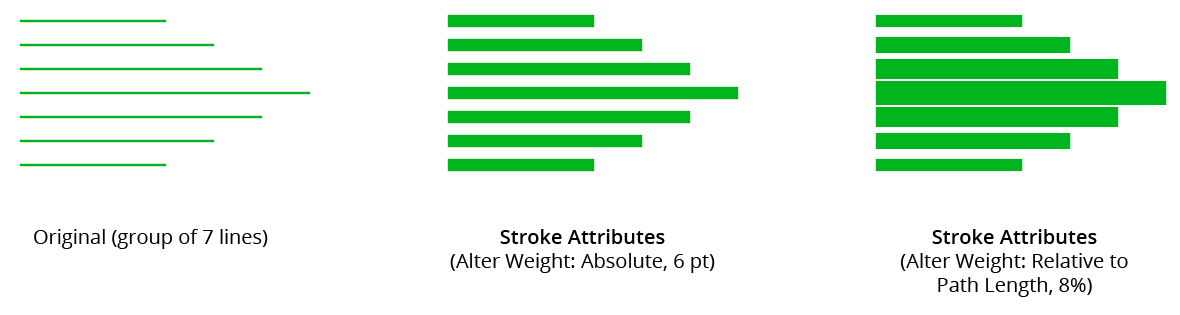
AG Utilities Live Effects - Stroke Attributes Example
4. Limit, Minimum Value
Any base weights smaller than this will be changed to this value.
5. Limit, Maximum Value
Any base weights larger than this will be changed to this value.
6. Alter End Caps
When enabled, the end cap type of the stroke is changed to the specified type.
7. End Cap Type
As per the native stroke panel, the type of end cap to use: Butt, Round, or Projecting.
8. Alter Corner Joins
When enabled, the corner join type of the stroke is changed to the specified type.
9. Corner Join Type
As per the native stroke panel, the type of corner join to use: Miter, Round, or Bevel.
10. Miter Limit
For Miter type joins, per the native stroke panel, the miter limit to use.
11. Randomize
Allows randomization of the final stroke weight. This option is only available when Alter Weight is enabled.
12. Distribution Curves
Specifies either a linear distribution in random values (all values in the range are equally likely to be chosen) or a Gaussian distribution (central values in the range are more likely to be chosen).
13. Seed
Each random seed number leads to a different sequence of random values. Clicking the button picks a new seed, thereby changing the look of the artwork. To view or specify the seed number directly, Option/Alt-click the button. This lets you recreate a previously-generated look.
14. Weight Variation
Specifies the maximum amount of variation in the final stroke weight. For example, if the weight is set to 20 pt, then a variation value of 25% would produce weights that vary by as much as 20pt × 25% = 5 pt, that is, between 15 pt and 20 pt; a variation value of 90% would produce weights between 2 pt and 20 pt.
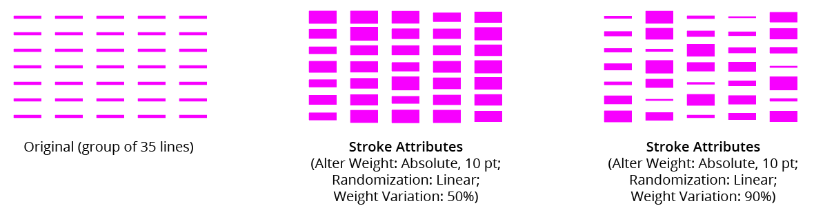
AG Utilities Live Effects - Stroke Attributes Randomization Examples
15. Force Stroke On Fill-Only Paths
When enabled, a stroke will be added to any paths which are fill-only, if at least one attribute (weight, caps, or joins) is specified. For non-specified attributes, default values will be used. The color of the stroke will be the same as the fill color.
16. And Remove Fill
When enabled, the fill of the path will be removed when the new stroke is added.
17. Preview
As with all live effects, when enabled, changing a parameter will immediately update the artwork while the dialog is still open.
18. Help Button
Opens the help documentation in the Astute Manager. If this does not automatically appear, please ensure your Astute Manager is running first.