Effect
Stipple Live Effect
Symbol Stipple Live Effect
Curves
Desaturate
Duotone
Exposure
Halftone
Perturb Live Effect
Color Randomizer Live Effect
Opacity Randomizer Live Effect
AG Architect Live Effect
Hue/Saturation
Invert
Levels
Prepress Correct
Shift to Color
Temperature/Tint
AG Splatter Live Effect
AG Curvature Visualizer Live Effect
AG Corners Live Effect
 Stylism
 Width Stamp
 Phantasm Controls
Stylism Tool
![]() Randomino Panel
Randomino Panel
 Halftone
 AG Architect Live Effect
AG Architect Panel
 AG Block Shadow
AG Block Shadow Tool
AG Block Shadow Panel
 AG Offset
AG Offset Tool
 AG Splatter Live Effect
 AG Curvature Visualizer Live Effect
![]() Live Effect Parameter Editor
Live Effect Parameter Editor
 AG Utilities Live Effects
![]() AG Transform Live Effect
AG Transform Live Effect
![]() Angle Cap Live Effect
Angle Cap Live Effect
Illustrator Location:
Illustrator Main Menu > Effect > Stipplism > Stipple...
As with most live effects, Stipple appears in the main menu, at Effect > Stipplism > Stipple. It can also be applied directly from the Appearance panel using the “Add New Effect” button at the bottom of the panel.
Stipple Parameters Dialog
After applying the live effect using the menu item (or when clicking on the existing effect in the Appearance panel to edit it), the parameters dialog will appear:

Stipple Parameters Dialog
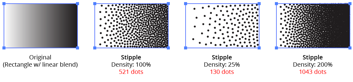
1. Density
Controls the overall density of the stipple dots (as a percentage of its full-strength value). The default value is 100%, but can vary between 0.01% and 1000%. Lower densities will result in fewer dots. If the Preview option at the bottom is enabled, the number of dots will be displayed.
Stipplism Density Example
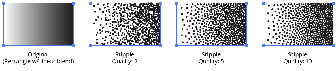
2. Quality
Controls the uniformity of the stipple dots. Values can range between 1 and 11, with a default of 3. Higher values result in more uniform patterns (and take longer to calculate).
Stipplism Quality Example
The range is not linear, but is based on a logarithmic scale. Each step up in Quality roughly doubles (or more) the amount of time required to create the dots. For example, 10,000 dots typically take less than 2 seconds to create at qualities of 4 or less, but 5 seconds at quality 6, 30 seconds at quality 9, and about 300 seconds at quality 11. Therefore, for Stipples with large numbers of dots, it’s recommended to start with a low Quality value and increase it later when the design is nearly finalized. If there are many Stipples in the document, creating Graphic Styles may be useful.
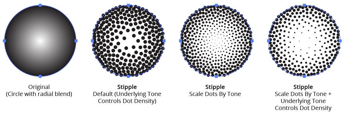
3. Underlying Tone Controls Dot Density
When enabled, the default, the lightness (tone) of the selected artwork controls the density of the generated dots, with lighter areas getting fewer dots. This underlying tone must control either the density of the dots or their size (or both), so when this setting is disabled, the Scale Dots By Tone setting will automatically be enabled.
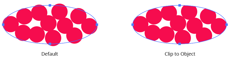
4. Clip to Object
When enabled, the outlines of the selected artwork (including those of strokes and prior effects) are used as a clipping mask for the generated dots, ensuring they do not protrude beyond these outlines.
Stipplism Clip to Object Example
5. Size
Controls the size (diameter) of the stipple dots; the default size is 6 pt / 2 mm. If Scale Dots by Tone is enabled, each dot’s size will be further modified by the curve applied.
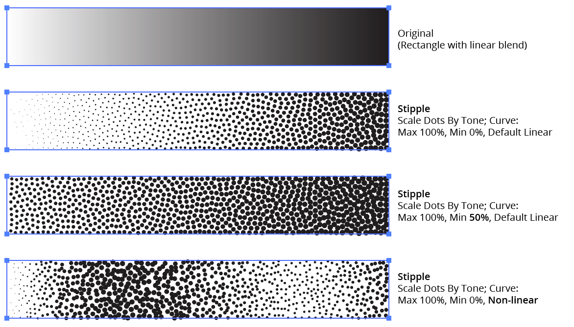
6. Scale Dots By Tone
Traditionally, stippling is made using dots which are the same size, with only the number of dots in any area (dot density) used to produce different gray levels. However, when this setting is enabled, Stipple will use the lightness (tone) of the artwork to control the size of the dots (relative to the specified Size), with a graph specifying the relationship between size and tone. Underlying Tone Controls Dot Density can enabled as well, in which case the tone will control both dot size and dot density. When this setting is disabled, the Underlying Tone Controls Dot Density setting will automatically be enabled, as the tone must control at least one or the other.
Stipplism Scale by Tone Example
7. Graph Maximum Value
The factor by which the base Size is multiplied (from 0 to 1000%) to calculate the dot size for tone values where the graph curve is at the top.
8. Graph Minimum Value
The factor by which the base Size is multiplied (from 0 to 1000%) to calculate the dot size for tone values where the graph curve is at the bottom. This allows, for example, the ability to keep the dots from becoming too small by forcing them to start at a certain percentage of the base size.
9. Graph
Available when the Scale Dots By Tone setting is enabled. The graph controls the relationship of the scale of the dots (on the vertical axis) to the tone (the horizontal gradient ramp at the bottom of the graph). In its default state, a diagonal line represents a linear relationship. Points can be added along the line and freely moved on the grid. To delete a point, drag it outside of the grid. Clicking the gradient ramp under the graph with Shift held will reset the graph to the default linear type.
Stipplism Curve Examples
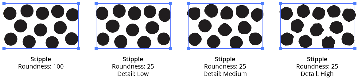
10. Roundness
By default, each stipple dot is a perfect circle, but the Roundness value can be lowered (with a minimum of zero) to make them more irregular. The smaller the Roundness value, the larger the displacement of each dot’s path will be from a true circle.
11. Detail
When Roundness is anything other than 100, the Detail dropdown menu is available. It allows a choice of four options: Low (the default), Medium, High, and Very High. Higher Detail creates more anchor points around the dot’s edge.
Stipplism Roundness and Details Example
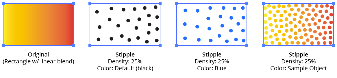
12. Color
Specifies the color of the stipple dots. By default, this is set to a fixed value: black. Clicking the color chip will bring up the native Color Picker dialog, allowing a different color to be used.
13. Sample Object
When selected, the stipple dots will automatically pick up the underlying colors of the original artwork at each dot location. Because colors are sampled uniformly without regard to their lightness, the base density of the Stipple is calculated as if the object were totally black.
Stipplism Color Examples
14. Overprint
Specifies whether the stipple dots should be overprinted — that is, if Illustrator should still print all the non-shared inks behind the dots rather than cut holes under them (knockout). This is useful mainly in CMYK documents destined for print. The default value is enabled. Pure white dots will never be set to overprint, regardless of the setting.
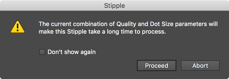
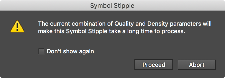
15. Ignore Slow Processing Warning
Using the effect with a small Size value and/or a high Density (i.e., high dot counts), especially combined with higher Quality values, will require long periods of time to calculate. When this is the case, by default a warning dialog will be displayed asking for confirmation to proceed. By enabling this setting, the specific Stipple to which it is applied will never show the warning dialog.
Stipplism Warning Dialog
16. Reset Warning button
The Slow Processing Warning dialog can be kept from being displayed again by enabling its Don’t show again checkbox. Thereafter, to re-enable the warning, use the Reset Warning button.
17. Preview
By default this option is disabled and not sticky, since the calculation of the Stipple effect can be slow when its settings are high. However, it can be made sticky by clicking with Option/Alt held down.
18. Dot Count
Available when Preview is enabled; shows the number of stipple dots that were generated with the current settings.
19. Help Button
Opens the help documentation in the Astute Manager. If this does not automatically appear, please ensure your Astute Manager is running first.
Illustrator Location:
Illustrator Main Menu > Effect > Stipplism > Symbol Stipple...
As with most live effects, Symbol Stipple appears in the main menu, at Effect > Stipplism > Symbol Stipple. It can also be applied directly from the Appearance panel using the “Add New Effect” button at the bottom of the panel.
Symbol Stipple Parameters Dialog
After applying the live effect using the menu item (or when clicking on the existing effect in the Appearance panel to edit it), the parameters dialog will appear:

Symbol Stipple Parameters Dialog
1. Seed
When dealing with symbols instead of simple round dots like the Stipple effect, positioning can matter more for the final look of the artwork. Each seed number leads to a different sequence of random values used to position the dots, some of which may produce nicer-looking results than others.
2. Randomize button
Each press of the Randomize button generates a new seed value, chosen at random.
3. Store/Recall buttons
The Store button records the current seed value; the Recall button will load the stored value back into the Seed field. When the dialog is first opened, the stored value is automatically set to the current seed.
4. Previous/Next Seed buttons
The dialog keeps track of all entered or generated seed values for the current session, and these buttons can be used to step through the history, both forwards and backwards. Once the dialog is OK’d or canceled, this history is cleared.
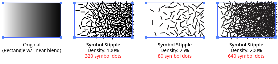
5. Density
Controls the overall density of the symbol dots (as a percentage of its full-strength value). The default value is 100%, but can vary between 0.01% and 10000%. Lower densities will result in fewer symbol dots. If the Preview option at the bottom is enabled, the number of dots will be displayed.
Symbol Stipple Density Example
6. Quality
Controls the uniformity of the stipple dots. Values can range between 1 and 11, with a default of 3. Higher values result in more uniform patterns (and take longer to calculate).
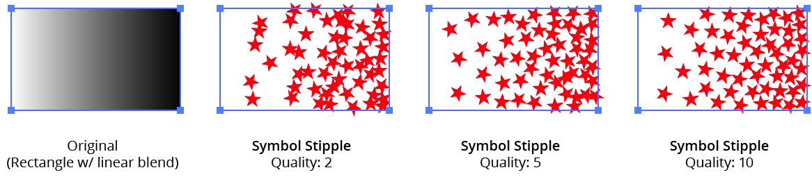
Symbol Stipple Quality Example
The range is not linear, but is based on a logarithmic scale. Each step up in Quality roughly doubles (or more) the amount of time required to create the dots. For example, 10,000 dots typically take less than 2 seconds to create at qualities of 4 or less, but 5 seconds at quality 6, 30 seconds at quality 9, and about 300 seconds at quality 11. Therefore, for Symbol Stipples with large numbers of dots, it’s recommended to start with a low Quality value and increase it later when the design is nearly finalized. If there are many Symbol Stipples in the document, creating Graphic Styles may be useful.
7. Underlying Tone Controls Dot Density
When enabled, the default, the lightness (tone) of the selected artwork controls the density of the generated dots, with lighter areas getting fewer dots. This underlying tone must control either the density of the dots or their size (or both), so when this setting is disabled, the Scale Dots By Tone setting will automatically be enabled.
8. Clip to Object
When enabled, the outlines of the selected artwork (including those of strokes and prior effects) are used as a clipping mask for the generated dots, ensuring they do not protrude beyond these outlines.
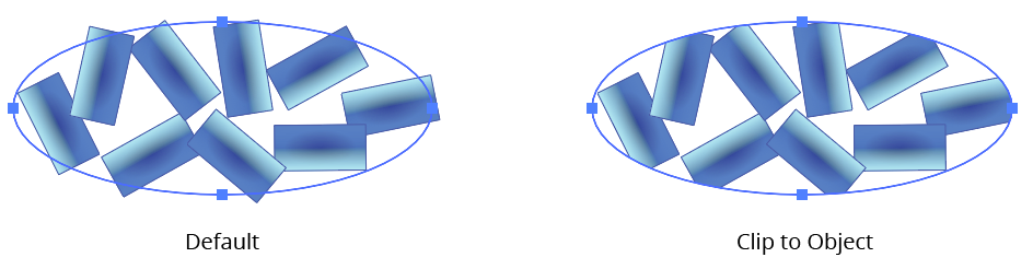
Symbol Stipple Clip to Object
9. Symbol
Specifies the symbol to be used as the stippling dot, from all the symbols available in the native Symbols panel. By default, the first symbol in the panel is used. If a document has no symbols at all, applying the effect won’t produce visible results, so at least one symbol should be created beforehand.
10. Include Variants
If the chosen symbol from the Symbol dropdown list has “variants,” this setting (enabled by default) allows them to be used in addition to the base symbol. The variants must have been created before applying the Symbol Stipple effect to the artwork. See below for information on variants and how to create them. The number of variants found will be displayed in parentheses.
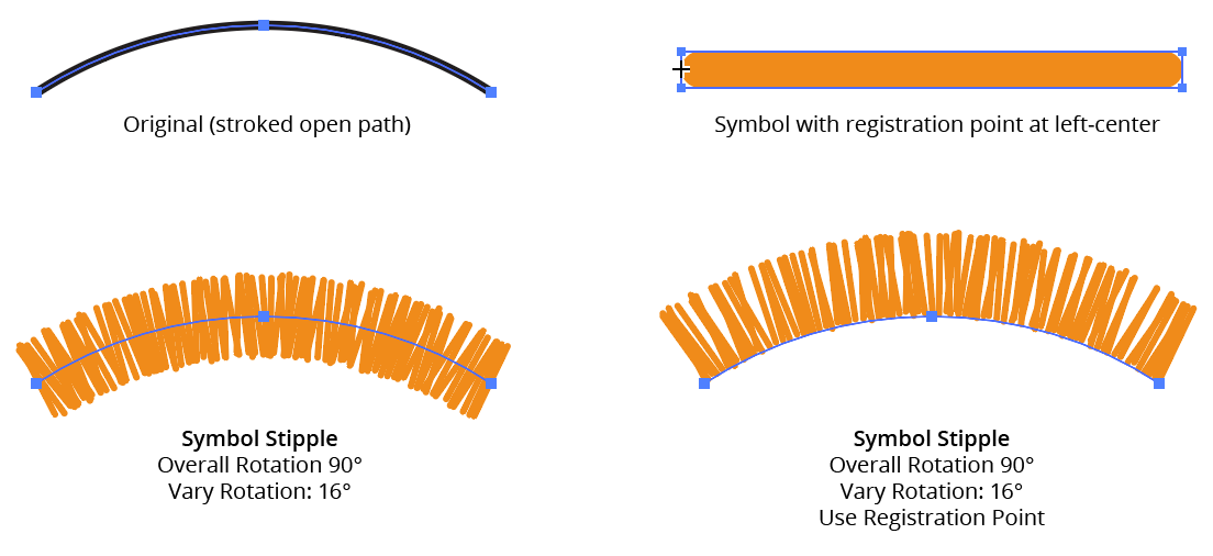
11. Use Registration Point
When creating a symbol, Illustrator allows a registration point to be set for it, using a standard nine-block grid control. It can be treated as a pivot used for rotating a symbol and as the center of its coordinates. When Use Registration Point is disabled, Symbol Stipple assumes the pivot of the symbol is at its geometric center. When enabled, the effect treats the registration point as the pivot.
Symbol Stipple Use Registration Point
12. Overall Scale
Specifies the scale value for all of the symbol dots, relative to the original size of the chosen symbol (or its variants). The default value is 100%. If Scale Dots by Tone is enabled, each dot’s size will be further modified by the curve applied.
13. Vary Scale
When enabled, the Vary Scale value sets the factor which will be used to randomly scale each symbol dot in either the up or down direction. For example, if it is set to 4, each symbol dot will be randomly scaled in the range of 25% (one-quarter) to 400% (four times) the Overall Scale value.
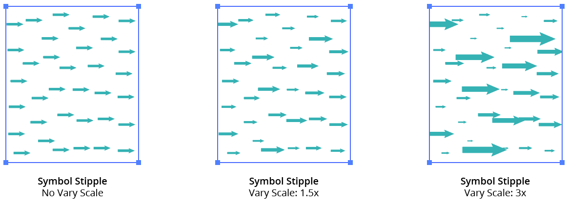
Symbol Stipple Vary Scale
14. Overall Rotation
Specifies the angle to which all the symbol dots are rotated. The default value is 0° (no rotation).
15. Vary Rotation
When enabled, the Vary Rotation value defines a range through which the symbol dots will be randomly rotated, in addition to the base Overall Rotation value. For example, if set to 90°, each symbol dot will be rotated to the Overall Rotation value, and then randomly rotated an additional amount from –45° to +45°. The default value is 360°, which means symbol dots would be rotated randomly to any angle.
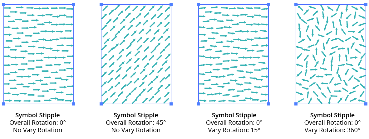
Symbol Stipple Vary Rotation
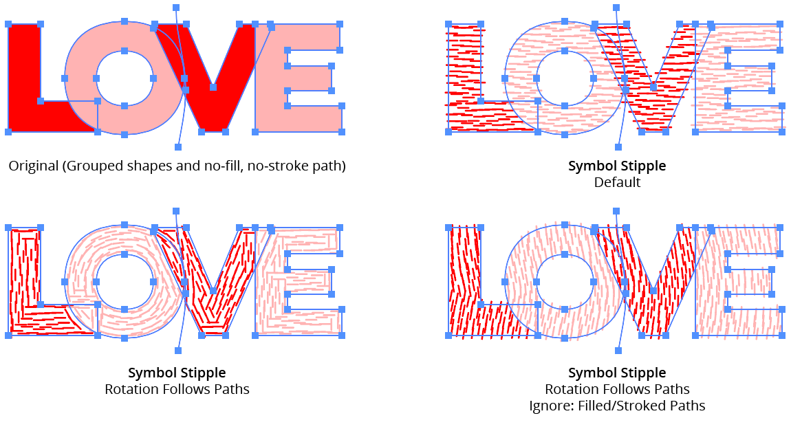
16. Rotation Follows Paths
When enabled, the effect rotates each symbol dot to the tangent angle of the nearest spot on the nearest path in the artwork (when possible) before adding the Overall Rotation and Vary Rotation values. The absolute distance from the artwork to the path is not important.
17. Ignore
When Rotation Follows Paths is enabled, this setting allows certain paths to be ignored when determining the rotation. The two options are Ignore Largest Path (valid when there is more than one path, and measured using bounding box area) and Ignore Filled/Stroked Paths. The latter is useful when applying Symbol Stipple to a group of multiple paths because the symbols’ rotation can be controlled by putting no-stroke, no-fill paths anywhere in the group.
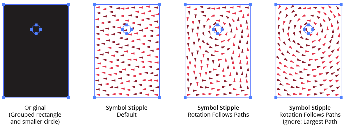
Symbol Stipple Follows Example 1
Symbol Stipple Follow Paths Example 2
18. Colorize
Allows the color of the generated symbol dots to be changed. When enabled and set to the color chip (which can be clicked to bring up the native Color Picker dialog), the specified color is used, replacing those used in all fills and strokes inside the chosen symbol (and, when applicable, its variants). If Sample Object is instead enabled, the symbol dots will automatically pick up the underlying colors of the original artwork at each dot location, again replacing those used in all fills and strokes inside the chosen symbol and variants. Because colors are sampled uniformly without regard to their lightness, when using Sample Object the base density of the Symbol Stipple is calculated as if the object were totally black.
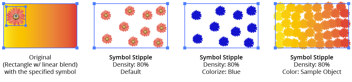
Symbol Stipple Colorize Example
19. Depth Sort
When enabled, changes the stacking order of the generated symbol dots. Dots can be sorted by their X-coordinate, their Y-coordinate, or their distance from a certain point on the artwork bounds. The last option uses the standard nine-point grid control to pick the point location.
20. Strength
Available when Depth Sort is enabled. The lower the Strength value, the less strict is the sorting, and the more randomness is introduced into the stacking order.
21. Reverse Order
Available when Depth Sort is enabled; it reverses the normal stacking order.
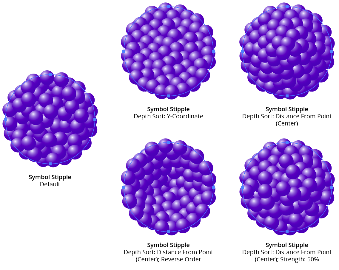
Symbol Stipple Available when Depth Sort is enabled
22. Scale Dots By Tone
Traditionally, stippling is made using dots which are the same size, with only the number of dots in any area (dot density) used to produce different gray levels. However, when this setting is enabled, Symbol Stipple will use the lightness (tone) of the artwork to control the size of the dots (relative to the specified Size), with a graph specifying the relationship between size and tone. Underlying Tone Controls Dot Density can enabled as well, in which case the tone will control both dot size and dot density. When this setting is disabled, the Underlying Tone Controls Dot Density setting will automatically be enabled, as the tone must control at least one or the other.
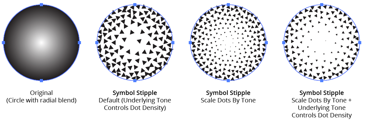
Symbol Stipple Scale by Tone Example
23. Graph Maximum Value
The factor by which the base Size is multiplied (from 0 to 1000%) to calculate the dot size for tone values where the graph curve is at the top.
24. Graph Minimum Value
The factor by which the base Size is multiplied (from 0 to 1000%) to calculate the dot size for tone values where the graph curve is at the bottom. This allows, for example, the ability to keep the dots from becoming too small by forcing them to start at a certain percentage of the base size.
25. Graph
Available when the Scale Dots By Tone setting is enabled. The graph controls the relationship of the scale of the dots (on the vertical axis) to the tone (the horizontal gradient ramp at the bottom of the graph). In its default state, a diagonal line represents a linear relationship. Points can be added along the line and freely moved on the grid. To delete a point, drag it outside of the grid. Clicking the gradient ramp under the graph with Shift held will reset the graph to the default linear type.
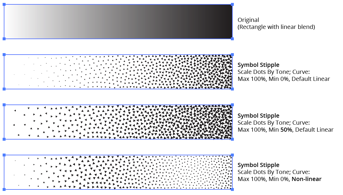
Symbol Stipple Curve Examples
26. Ignore Slow Processing Warning
Using the effect with a small Size value and/or a high Density (i.e., high dot counts), especially combined with higher Quality values, will require long periods of time to calculate. When this is the case, by default a warning dialog will be displayed asking for confirmation to proceed. By enabling this setting, the specific Symbol Stipple to which it is applied will never show the warning dialog.
Symbol Stipple - Ignore Slow Processor Warning
27. Reset Warning button
The Slow Processing Warning dialog can be kept from being displayed again by enabling its Don’t show again checkbox. Thereafter, to re-enable the warning, use the Reset Warning button.
28. Preview
By default this option is disabled and not sticky, since the calculation of the Symbol Stipple effect can be slow when its settings are high. However, it can be made sticky by clicking with Option/Alt held down.
29. Dot Count
Available when Preview is enabled; shows the number of symbol dots that were generated with the current settings.
30. Tips Button
Displays a dialog summarizing how to use symbol variants, including an explanation of naming conventions (see Symbol Stipple Symbol Variants).
31. Help Button
Opens the help documentation in the Astute Manager. If this does not automatically appear, please ensure your Astute Manager is running first.
Illustrator Location:
Advanced Toolbar > Stylism Tool
Tool Location and Cursor Appearance
The Stylism tool appears in Illustrator’s main toolbar (which must be in Advanced mode: View > Toolbars > Advanced).
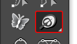
Stylism Tool Location
The Stylism tool’s primary cursor is a crosshair. When interacting with the annotated controls, it can assume other forms:
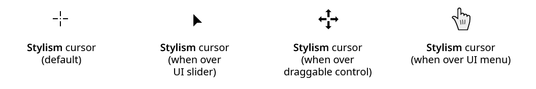
Stylism Tool Cursors
Tool Operation
As the Stylism tool has several keypresses that modify its behavior in different contexts, we suggest installing the free Astute Graphics plugin Astute Buddy, which creates a panel that dynamically updates to inform you of the various keys which can be pressed in the tool’s current context.
The Stylism tool is works in conjunction with the associated Stylism panel, which should be open and accessible. If you are using the free Astute Graphics plugin DirectPrefs, you can have the Stylism panel automatically be shown when the Stylism tool is selected.
To use the Stylism tool, at least one art object must be selected that has in its appearance one of the eight native live effects that Stylism supports (Drop Shadow, Feather, Inner Glow, Outer Glow, Transform, Free Distort, Offset Path, and Gaussian Blur). If this is the case, the art will display (in red, by default) annotated controls (sliders, buttons and dropdown menus) that the tool can interact with to change the effect’s parameters. The controls are always centered over the bounding box of the art object. Common to all effects is a center circle control; the other controls are specific to each live effect.
Illustrator Location:
Illustrator Main Menu > Window > Astute Graphics > Width Stamp
Menu items to show and hide the Width Stamp panel can be found in the main menu under Window > Astute Graphics > Width Stamp. If the Width Stamp object is created using one of the main menu Object > Width Stamp > Make… items, the panel will be automatically shown if it is not already open.
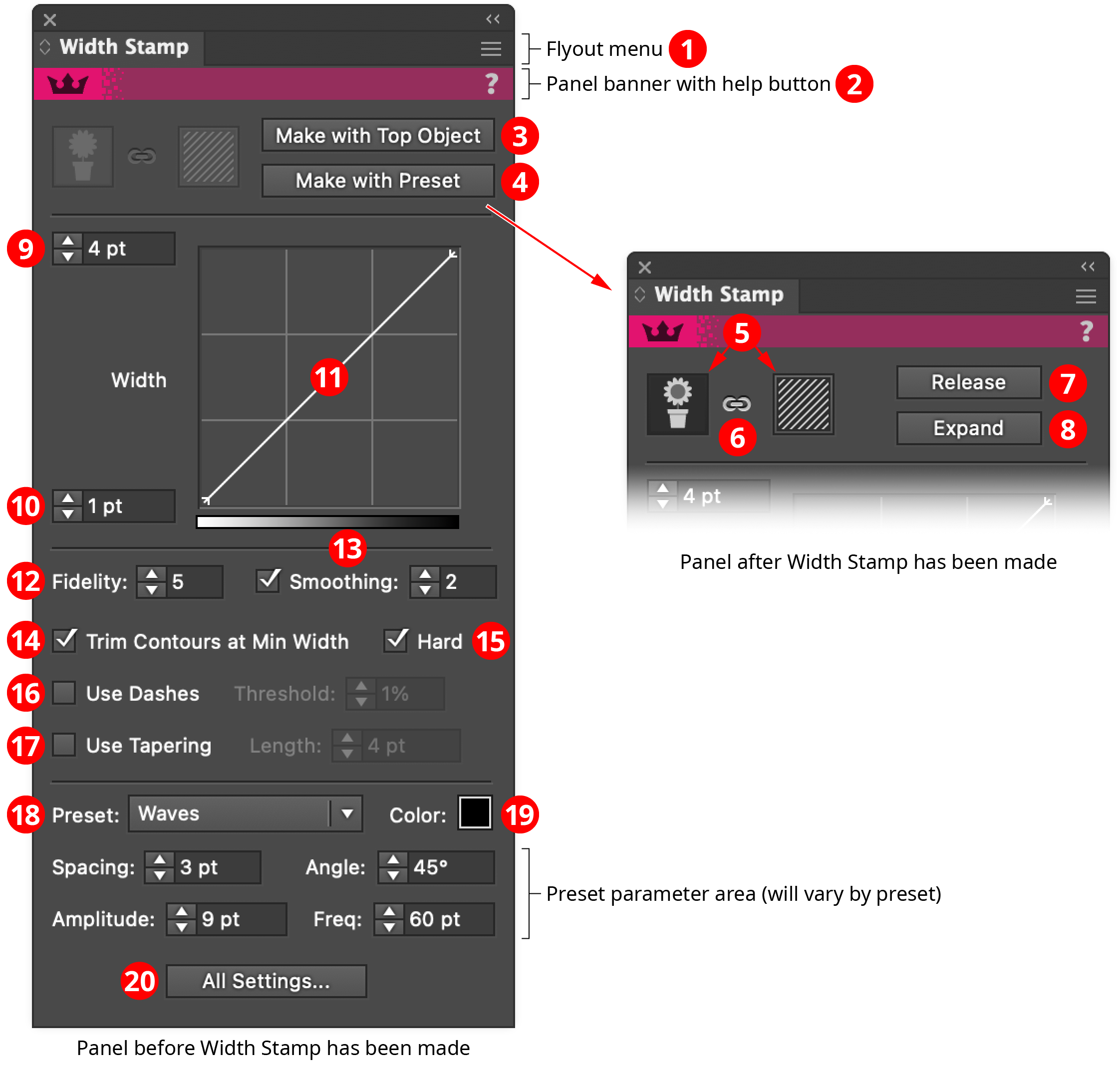
Width Stamp Panel
1. Flyout menu
See Width Stamp Panel: Flyout Menu.
2. Panel banner
The Width Stamp panel banner has a help button on the right which opens the help documentation in the Astute Manager. If this does not automatically appear, please ensure your Astute Manager is running first.
3. Make With Top Object button
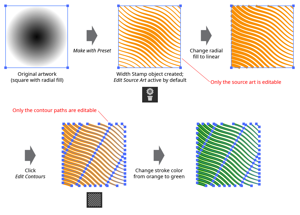
When the selection consists of artwork that is eligible to be turned into a top-object Width Stamp (at least two art objects, and the topmost object is a path or a group that contains at least one path), the Make with Top Object button will be available. Clicking Make with Top Object creates a Width Stamp object from the selected artwork, using the parameters that are currently specified on the lower area of the panel. The bottom object is used as the grayscale source, while the path(s) above it, which must have a stroke, are used as the contours and will have their widths changed to reflect the grayscale values, according to the width settings and curve on the panel.

Width Stamp Make with Top Object Example
To edit the contour paths that were in the top object once the Width Stamp object has been created, either release the Width Stamp (see Release button) or click the Edit Contours button (see Edit Source Art/Contours buttons).
A Width Stamp (from top object) can also be made using the main menu item Object > Width Stamp > Make With Top Object….
4. Make With Preset button
When at least one piece of artwork is selected, the Make with Preset button will be available. Clicking Make with Preset creates one Width Stamp object for each selected piece of art, using the parameters that are currently specified on the lower area of the panel (to make a single Width Stamp object from multiple pieces of art, group them first). The contours are not created from existing art, but are generated algorithmically, their geometry determined by the type of preset (see Preset Menu below).

Width Stamp Make with Preset Example
A Width Stamp (from preset) can also be made using the main menu item Object > Width Stamp > Make With Preset….
5. Edit Source Art/Contours buttons
When at least one Width Stamp object is selected, the Edit Source Art button and the Edit Contours button will be available. Only one of the two buttons can be active at any time; the active button is distinguished by a darker border. When Edit Source Art is active (which is the default after a new Width Stamp object is created), the source art, which provides the grayscale values, is editable (although it will appear empty), while the contour paths are visible but not editable. When Edit Contours is active, the contour paths are visible and editable, while the source art is hidden and cannot be edited.
Width Stamp Edit Source Art vs. Edit Contours
Note: If a Width Stamp object that was made with a preset is active when the Edit Contours button is pressed, its contour paths become normal editable paths, and the preset parameters will no longer be available to change (in other words, it is as if the Width Stamp had been made using a top object).
6. Link/Unlink button
When at least one Width Stamp object is selected, the Link/Unlink button will be available. Clicking it toggles between linked and unlinked states. When linked, transformations (moving, scaling, rotating) made to the source art will similarly affect the contour art, and vice versa. When unlinked, transformations can be made to either the source art or contour art independently (however, if the Width Stamp was made from a preset, the Edit Contours button must be pressed before the source art and contour art will become unlinked).

Width Stamp Edit Linked vs. Unlinked
Note: Illustrator’s Real-Time Drawing and Editing (when using GPU preview) does not properly handle the case of moving the source art when linking is disabled: it appears to move both the source and the contours together, until the mouse button is released. Pressing Shift while moving the source art usually rectifies this.
7. Release button
Clicking Release restores all selected Width Stamp objects to their original component object or objects, which may then be edited and, if desired, made into Width Stamps again.

Width Stamp Release Example
Width Stamps can also be released using the main menu item Object > Width Stamp > Release.
8. Expand button
Clicking Expand “flattens” and removes all selected Width Stamp objects; the resulting variable width paths can subsequently be edited like any other art objects. Each expanded Width Stamp is placed into a group.

Width Stamp Expand Example
Width Stamps can also be expanded using the main menu item Object > Width Stamp > Expand.
9. Width Value 1
(This control may not visible if Hide Curve has been chosen from the panel flyout menu.) Because it is at the top, this value can be thought of as the “maximum” value, although it can be set to any value. When the graph curve is set to the default (a straight line rising from lower left to upper right), it controls the width of the contours where the underlying art is darkest.
10. Width Value 2
(This control may not visible if Hide Curve has been chosen from the panel flyout menu.) Because it is at the bottom, this value can be thought of as the “minimum” value, although it can be set to any value. When the graph curve is set to the default (a straight line rising from lower left to upper right), it controls the width of the contours where the underlying art is lightest.
11. Graph
(This control may not visible if Hide Curve has been chosen from the panel flyout menu.) The graph specifies the relationship between the width values and the grayscale values in the source art. The horizontal axis represents grayscale values (from white to black), while the vertical axis represents the width amount, specified by the “maximum” and “minimum” value inputs. With the default diagonal line, the relationship is a linear one.
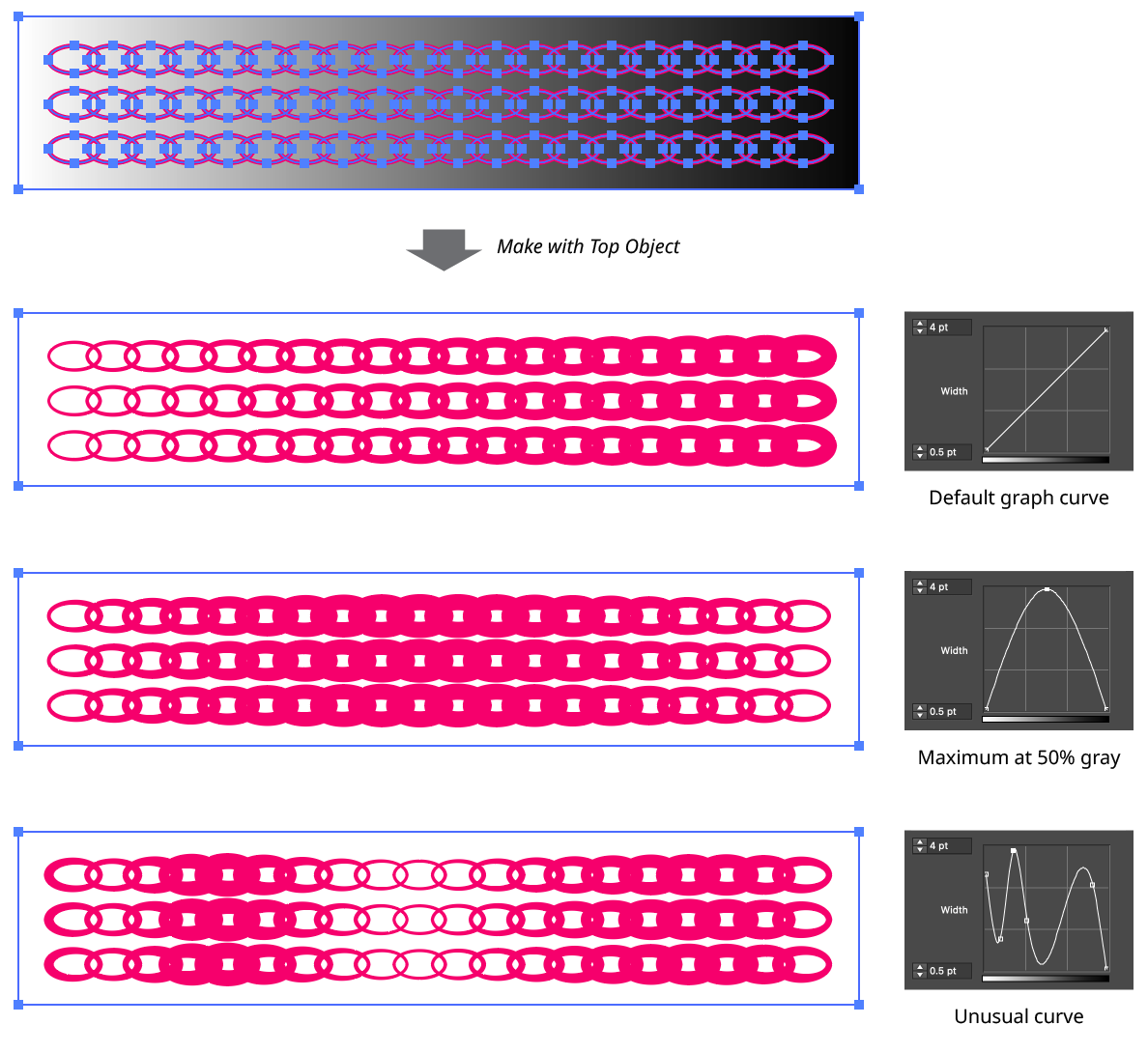
Width Stamp Graph Examples
Nodes on the curve may be moved simply by clicking and dragging them. A new node may be added by clicking at a spot along the curve which does not already have a node. Nodes (except the ones at the beginning and the end of the curve) may be deleted by dragging them off the graph area. The graph can be returned to its default linear state by holding down Shift and clicking on the thin gradient band underneath it.
12. Fidelity
Controls how accurately the grayscale levels of the source art are translated to width markers along the strokes of the contours. The value can range from 1 to 10. High values internally rasterize the source art at a higher resolution, and more closely space the width markers along the contours.

Width Stamp Fidelity Examples
13. Smoothing
When using high Fidelity values on a noisy image, the resulting variable width contours may appear “jagged” as their widths change abruptly over small distances. To alleviate this, the Smoothing setting can be enabled. Smoothing acts as a sort of Gaussian blur on the width markers, smoothing the width changes of adjacent markers:
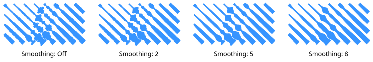
Width Stamp Smoothing Examples
14. Trim Contours at Min Width
When enabled, contours which reach the “minimum” width (the width specified in the lower Width Value 2 control) are trimmed off at that value. For the typical curve which has a node at the bottom left, this has the effect of removing contours where the underlying image or artwork is white:

Width Stamp Trim Contours
When using Trim Contours at Min Width, a high Fidelity setting is often necessary to keep the shape of the trimmed edges smooth.
15. Hard
When Trim Contours at Min Width is enabled, and Use Tapering is not enabled, the tips of the contours do not always look pleasing when the underlying grayscale values change from a dark to white in a sharp manner (thereby creating two markers of relatively high width followed by a single marker of zero width at the end of the path). To remedy this, the Hard parameter can be enabled, which forces the contour trim point to be at the next width maker past the minimum width one:

Width Stamp Trim Contours Hard
16. Use Dashes
When enabled, contours which would normally be below a threshold width will not get any thinner, but will instead change to a dashed appearance, with the dashes getting shorter as the underlying grayscale values get lighter. Dash length depends on the Fidelity and whether Dash Reduction is enabled (the latter setting is not available directly on the panel but can be accessed through the All Settings... dialog).

Width Stamp Use Dashes
The threshold value is specified as a percentage of the minimum-to-maximum range. For example, a threshold value of 25% means the contours will become dashed whenever their calculated width falls in the last quarter of that range. Use Dashes and Use Tapering cannot both be enabled.
17. Use Tapering
When enabled, all contours will have ends that taper to zero width, using the specified length:

Width Stamp Use Tapering
Use Tapering and Use Dashes cannot both be enabled.
18. Preset
The popup menu allows a choice of eight different presets, each of which creates contour lines with a different geometry controlled by preset-specific parameters. The presets are Half Grid, Grid, Waves, Zigzag, Concentric Circles, Concentric Squares, Circular Spiral, and Square Spiral:
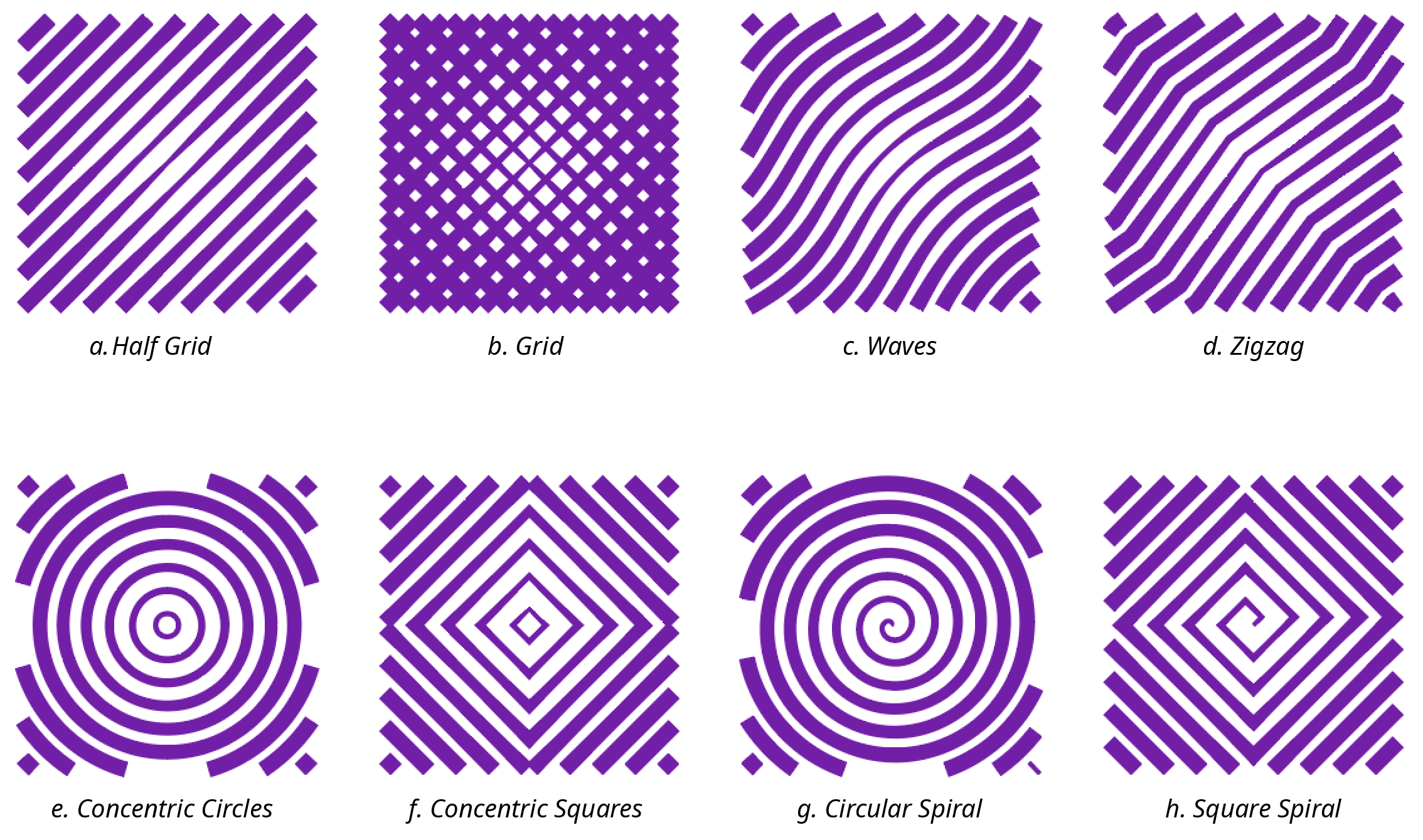
Width Stamp Presets
a. Half Grid
The Half Grid preset creates contours that consist of one set of parallel straight lines. The lines can have their spacing and angle specified.

Width Stamp Half Grid Preset Parameters
b. Grid
The Grid preset creates contours that consist of two sets of parallel straight lines. Each set of lines can have their spacing and angle specified independently.

Width Stamp Grid Preset Parameters
c. Waves
The Waves preset creates contours that consist of roughly parallel lines which curve back and forth like a wave. Their spacing and angle can be specified, as well as the amplitude and frequency of the waves.

Width Stamp Waves Preset Parameters

Width Stamp Waves Preset Examples
d. Zigzag
The Zigzag preset creates contours that consist of parallel lines in a herringbone pattern. Their spacing and angle can be specified, as well as the amplitude and frequency of the “zigzags.”

Width Stamp Zigzag Preset Parameters
e. Concentric Circles
The Concentric Circles preset creates contours that consist of closed, circular paths (or sections thereof) with the same center point. The circles have equal space between them, the value of which can be specified. The diameter of the innermost circle is equal to this spacing value.

Width Stamp Concentric Circles Preset Parameters
f. Concentric Squares
The Concentric Squares preset creates contours that consist of closed, square paths (or sections thereof) with the same center point. The squares have equal space between them, the value of which can be specified (as well as their angle). The side length of the innermost square is equal to the spacing value.

Width Stamp Concentric Squares Preset Parameters
g. Circular Spiral
The Circular Spiral preset creates contours that consist of an Archimedean spiral, where each revolution of the spiral lies a fixed distance from the previous one. This spacing value can be adjusted, as well as the angle at which the spiral initially heads, and whether the spiral is in the clockwise or counterclockwise direction.

Width Stamp Circular Spiral Preset Parameters

Width Stamp Circular Spiral Preset Examples
h. Square Spiral
The Square Spiral preset creates contours that consist of a square spiral (also described as a 4-angle spirangle). Its spacing value and angle can be adjusted, as well as whether the spiral is in the clockwise or counterclockwise direction.
Width Stamp Square Spiral Preset Parameters
19. Color
The color of the preset contours. Clicking the color chip will bring up the standard color picker dialog. To customize the colors (e.g. use different colors for different contours, or use a gradient or pattern for the strokes), convert the preset contours to ordinary paths by clicking the Edit Contours button.
20. All Settings...
In order to remain at a reasonable size, the Width Stamp panel only contains controls for the most-commonly used settings. After clicking the All Settings... button, the Width Stamp Settings Dialog opens, which offers controls for all of the panel settings as well as for several additional lesser-used settings.
Illustrator Location:
Illustrator Main Menu > Window > Astute Graphics > Phantasm
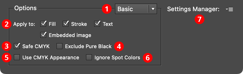
Except for Duotone, Halftone, and Prepress Correct, all of the live effects in Phantasm include a common Options section, which can be in either Basic or Advanced mode. In Basic mode the controls are as follows:
Phantasm Common Options Basic
1. Basic/Advanced Menu
Switches the Options section between Basic mode and Advanced mode.
2. Apply To
Allows the effect to be applied to only certain portions of the artwork or to only certain types of artwork. For example, if the Fill checkbox is unchecked, the effect will not change any fills in the artwork. If the Text checkbox is unchecked, text objects will not be changed.
3. Safe CMYK
Available if the document’s color mode is set to CMYK. When enabled, changed colors will have their ink levels adjusted to conform to the color settings in regards to total ink coverage.
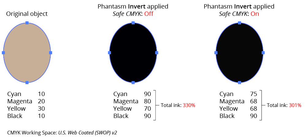
Phantasm Safe CMYK Example
4. Exclude Pure Black
Available if the document’s color mode is set to CMYK and Safe CMYK is enabled. When enabled, and the changed color has only a black component, the Safe CMYK adjustment, which usually has the effect of adding C, M, and Y components, will not be applied to that color.
5. Use CMYK Appearance
Available if the document’s color mode is set to CMYK. When enabled, a color’s grayscale equivalent (which is used when ignoring Rich Black or White in Advanced mode) is derived from its on-screen (RGB) appearance rather than directly from its CMYK value.
6. Ignore Spot Colors
When enabled, spot colors will never be modified by a Phantasm color change, even those that are allowed, such as increasing the brightness.
7. Settings Manager
The popup menu allows a complete set of options (from both the Basic and Advanced sections) to be saved and recalled. Additionally, the default and last used options can be restored.
Illustrator Location:
Advanced Toolbar > Stylism Tool
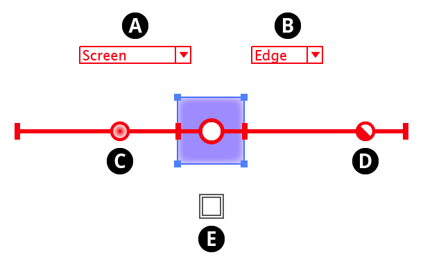
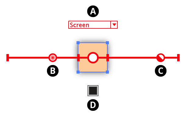
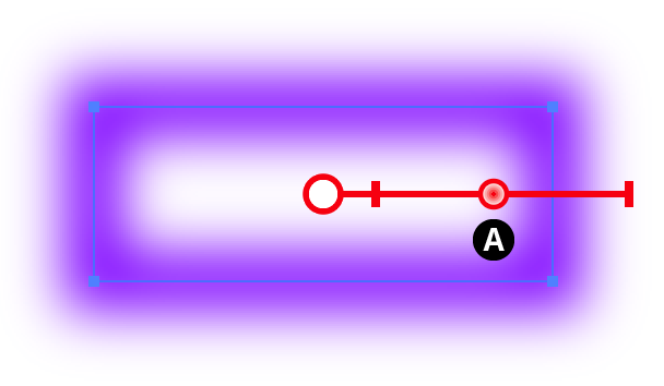
The interactive controls for the native Drop Shadow live effect consist of two sliders and a positioning arm extending from the center circle, along with a dropdown menu and a color chip:
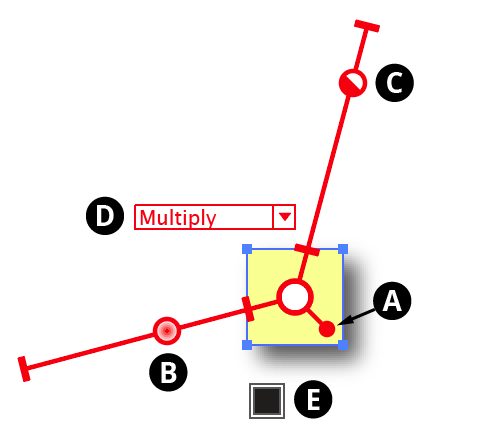
Stylism Drop Shadow Controls
A. Shadow Offset
The position of the small “ball” at the end of the shadow position arm in relation to the center circle reflects the offset of the drop shadow. When the cursor is hovering over the control, the current X and Y offsets are displayed. Dragging the control will update the shadow offset after the mouse button is released. The two sliders will rotate with the shadow offset control.
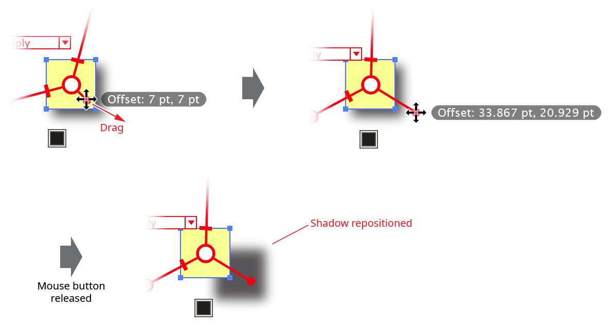
Stylism Drop Shadow Position Control
While dragging the shadow offset control, in addition to the common keypresses (see Stylism Annotated Controls and Common Drag Keypresses), the following keypresses can be used:
Shift: Constrains the angle of the shadow to 45° increments around the general constrain angle.
Option/Alt: Constrains the change in distance to integer values (or less, depending on the zoom level).
Doubleclicking the control brings up a dialog which allows you to enter the shadow offset numerically, either as the standard X and Y values, or as distance and angle values:
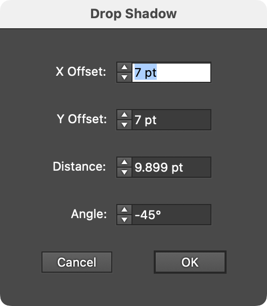
Stylism Drop Shadow Offset Dialog
B. Blur Slider
The blur slider thumb control may be dragged along the blur arm to change the shadow’s blur radius, between 0 and 144 pt. The value increases away from the center circle. When the cursor is hovering over the control or dragging it, the current blur radius is displayed. The blur slider can also be clicked anywhere along its length to move the blur thumb immediately to that position. While dragging the blur slider, in addition to the common keypresses (see Stylism Annotated Controls and Common Drag Keypresses), the following keypresses can be used:
Shift: Constrains the blur radius to integer values.
Doubleclicking the control brings up a dialog which allows you to enter the blur radius numerically.
C. Opacity Slider
The opacity slider thumb control may be dragged along the opacity arm to change the shadow’s opacity, between 0% and 100%. The value increases away from the center circle. When the cursor is hovering over the control or dragging it, the current opacity is displayed. The opacity slider can also be clicked anywhere along its length to move the opacity thumb immediately to that position. While dragging the opacity slider, in addition to the common keypresses (see Stylism Annotated Controls and Common Drag Keypresses), the following keypresses can be used:
Shift: Constrains the opacity to steps of 10%.
Doubleclicking the control brings up a dialog which allows you to enter the opacity numerically.
D. Blending Mode
The annotated blending mode dropdown menu allows you to select the shadow’s blending mode, from among Illustrator’s standard 16 blending modes:
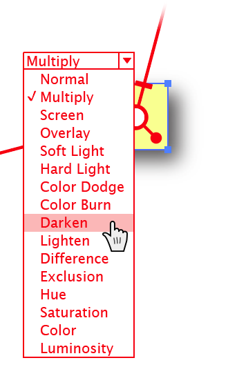
Stylism Drop Shadow Blending Mode Menu
E. Color
The color control shows the color of the shadow. To specify a new color, click the square to bring up the standard color picker. To switch from Color mode to Darkness mode, Option/Alt-click the control. A small “D” symbol is displayed to indicate Darkness mode. To change the darkness value, click the square.
Illustrator Location:
Advanced Toolbar > Stylism Tool
The interactive controls for the native Feather live effect consist of a single slider:
Stylism Feather Controls
A. Blur Slider
The blur slider thumb control may be dragged along the blur arm to change the feather’s blur radius, between 0.2 and 250 pt. The value increases away from the center circle. When the cursor is hovering over the control or dragging it, the current blur radius is displayed. The blur slider can also be clicked anywhere along its length to move the blur thumb immediately to that position. While dragging the blur slider, in addition to the common keypresses (see Stylism Annotated Controls and Common Drag Keypresses), the following keypresses can be used:
Shift: Constrains the blur radius to integer values.
Doubleclicking the control brings up a dialog which allows you to enter the blur radius numerically.
Illustrator Location:
Advanced Toolbar > Stylism Tool
The interactive controls for the native Inner Glow live effect consist of two sliders extending from the center circle, along with two dropdown menus and a color chip:
Stylism Inner Glow Controls
A. Blending Mode
The annotated blending mode dropdown menu allows you to select the inner glow blending mode, from among Illustrator’s standard 16 blending modes.
B. Glow Type
The annotated glow type dropdown menu allows you to select the glow type, which can be either Center or Edge.
C. Blur Slider
The blur slider thumb control may be dragged along the blur arm to change the inner glow’s blur radius, between 0 and 144 pt. The value increases away from the center circle. When the cursor is hovering over the control or dragging it, the current blur radius is displayed. The blur slider can also be clicked anywhere along its length to move the blur thumb immediately to that position. While dragging the blur slider, in addition to the common keypresses (see Stylism Annotated Controls and Common Drag Keypresses), the following keypresses can be used:
Shift: Constrains the blur radius to integer values.
Doubleclicking the control brings up a dialog which allows you to enter the blur radius numerically.
D. Opacity Slider
The opacity slider thumb control may be dragged along the opacity arm to change the inner glow’s opacity, between 0% and 100%. The value increases away from the center circle. When the cursor is hovering over the control or dragging it, the current opacity is displayed. The opacity slider can also be clicked anywhere along its length to move the opacity thumb immediately to that position. While dragging the opacity slider, in addition to the common keypresses (see Stylism Annotated Controls and Common Drag Keypresses), the following keypresses can be used:
Shift: Constrains the opacity to steps of 10%.
E. Color
The color control shows the color of the inner glow. To specify a new color, click the square to bring up the standard color picker.
Illustrator Location:
It is often desirable to have the same live effect applied to a number of objects but with different parameters. For example, you might want to apply an AG Offset to many objects with different distance values:
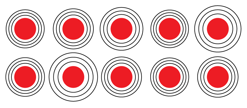
Different AG Offsets Example
Unfortunately, modifying each object one by one is time-consuming and tedious. However, using Randomino, you can instantly assign a random value across multiple objects to many different parameters from a number of common live effects, both native and from Astute Graphics:
Add Points: Seed
AG Block Shadow: Position
AG Offset: Distance
Color Randomizer: Hue Seed, Saturation Seed, Lightness Seed, Filter Seed
Dashify: Seed
Drop Shadow: Blur, Opacity, Position
Extend Path: Seed
Feather: Radius
InkFlow: Size
Inner Glow: Blur, Opacity
Make Shape: Seed
Opacity Randomizer: Variation Seed, Filter Seed
Outer Glow: Blur, Opacity
Path Removal: Seed
Point Removal: Seed
Phantasm: Brightness, Contrast, Hue, Hue (Colorizing), Saturation, Saturation (Colorizing), Lightness
Pucker & Bloat: Strength
Roughen: Size (Absolute), Size (Relative), Detail
Segment Removal: Seed
Stroke Attributes: Seed
When the Randomino panel kind is set to Live Effects, one, and possibly two, additional popup menus will appear on the panel:
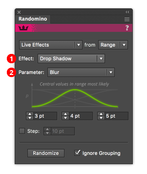
Randomino Panel Live Effect Callouts
1. Effect menu
Selects the live effect or family of effects to randomize.
2. Parameter menu
Appears if there are multiple parameters available within the live effect or family and allows you to select the parameter.
Tip: Artwork that does not have the specified live effect applied to it will not be changed; i.e., the live effect is not automatically added.
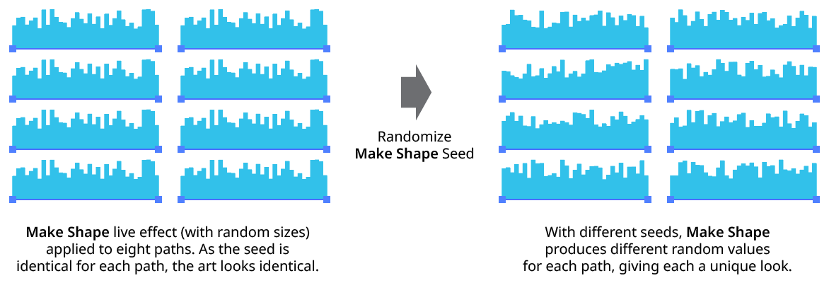
Randomino Randomize Seed
Illustrator Location:
Advanced Toolbar > Stylism Tool
The interactive controls for the native Outer Glow live effect consist of two arms extending from the center circle, along with one dropdown menu and a color chip:
Stylism Outer Glow Controls
A. Blending Mode
The annotated blending mode dropdown menu allows you to select the outer glow blending mode, from among Illustrator’s standard 16 blending modes.
B. Blur Slider
The blur slider thumb control may be dragged along the blur arm to change the outer glow’s blur radius, between 0 and 144 pt. The value increases away from the center circle. When the cursor is hovering over the control or dragging it, the current blur radius is displayed. The blur slider can also be clicked anywhere along its length to move the blur thumb immediately to that position. While dragging the blur slider, in addition to the common keypresses (see Stylism Annotated Controls and Common Drag Keypresses), the following keypresses can be used:
Shift: Constrains the blur radius to integer values.
Doubleclicking the control brings up a dialog which allows you to enter the blur radius numerically.
C. Opacity Slider
The opacity slider thumb control may be dragged along the opacity arm to change the outer glow’s opacity, between 0% and 100%. The value increases away from the center circle. When the cursor is hovering over the control or dragging it, the current opacity is displayed. The opacity slider can also be clicked anywhere along its length to move the opacity thumb immediately to that position. While dragging the opacity slider, in addition to the common keypresses (see Stylism Annotated Controls and Common Drag Keypresses), the following keypresses can be used:
Shift: Constrains the opacity to steps of 10%.
D. Color
The color control shows the color of the outer glow. To specify a new color, click the square to bring up the standard color picker.
Illustrator Location:
Advanced Toolbar > Stylism Tool
The interactive controls for the native Transform live effect are as follows:
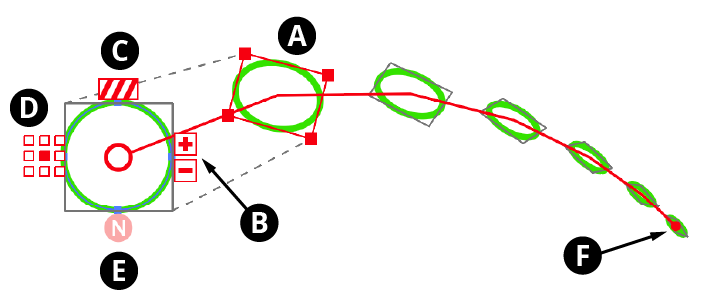
Stylism Transform Controls
A. Transformed Object Bounds
The bounds of the object after it has been offset, scaled, and rotated are indicated by a red rectangle with nodes at each corner. Dashed grey lines connect the corners of the rectangle with the original object’s bounds, indicated by a rectangle of solid grey lines. Each of the transform parameters may be changed by using the Stylism tool on this rectangle:
Offset: Hovering the cursor over the bounds rectangle (except over an edge or corner) displays the current offset values (
Option/Alt-clickingon the bounds toggles the readout between X/Y mode and distance/angle mode). Dragging the bounds rectangle (except on an edge or corner) changes the offset (holdShiftto constrain the motion to 45° increments around the general constrain angle). The rectangle may also bedoubleclickedto enter the offsets numerically, either as the standard X and Y values, or as distance and angle values:
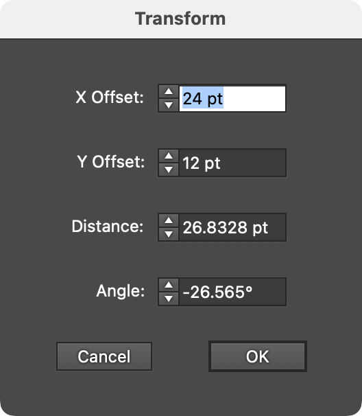
Stylism Transform Offset Dialog
Scale: Dragging one of the corner nodes of the bounds rectangle changes the scaling. Holding
Shiftwhile dragging constrains the aspect ratio. To change only the horizontal scale or only the vertical scale, drag an edge. To specify the scaling numerically,doubleclickone of the edges of corners:
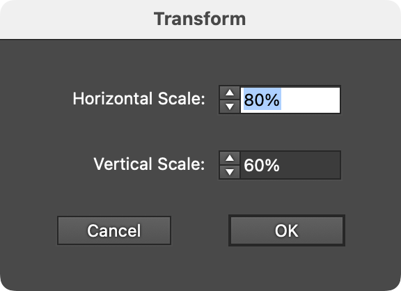
Stylism Transform Scale Dialog
Rotation: When the cursor if hovering outside the rectangle but near one of the corners, the current rotation value will be displayed. Dragging from this location changes the rotation. While dragging, holding
Shiftconstrains the rotation to 45° increments around the general constrain angle.Doubleclickingwhile the current rotation value is being displayed brings up a dialog letting you change the rotation value numerically:
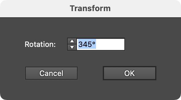
Stylism Transform Rotation Dialog
B. Increment/Decrement Copies
The buttons marked with “+” and “–” increment and decrement the number of transformed copies, from 0 to 1000. Pressing Shift while clicking a button will change the value by 10 instead of 1. Pressing Option/Alt while clicking the button will change number of copies while also retaining the position of the last transformed copy:
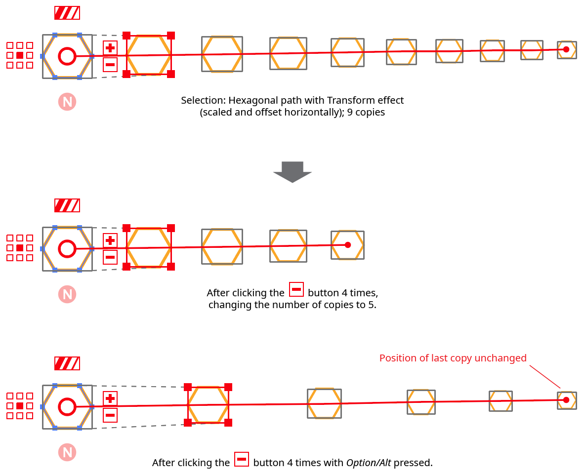
Stylism Transform Copies Button Example
Each copy is joined by a thin red line (the copy chain line), and each copy except the first has its bounding box marked with a rectangle of solid grey lines.
C. Scale Strokes & Effects
Controls the Scale Strokes & Effects setting. When disabled, it shows three stripes of the same width; when enabled, three stripes of varying widths. Clicking the button toggles the setting.
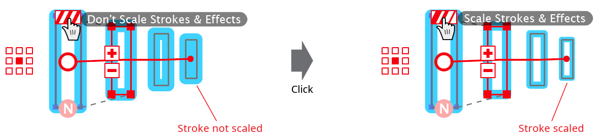
Stylism Transform Scale Strokes Example
D. Reference Point
This nine-block widget is similar to the smaller version in the Transform effect parameters dialog, and specifies the reference point (position of the transformation point relative to the bounds of the original object).
E. Randomize
Toggles the Random parameter of the live effect. When disabled, the button displays “N” (for non-random); when enabled, it displays “R”.
F. Transform Copy Chain Tip
Marks the position of the last copy in the copy chain. When the cursor is hovered over it, a display of the current number of copies will appear. Dragging the control changes the number of copies, extending or shortening the copy chain:
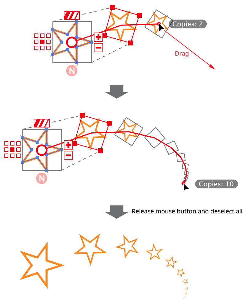
Stylism Transform Copy Chain Drag
Dragging the copy chain tip with Option/Alt held down allows you to move the position of the last copy (and, therefore, all intermediate copies) while retaining the current number of copies. Stylism achieves this by calculating and applying the necessary offset values such that the last copy lands at the given coordinates. The scaling and rotation values are not changed.
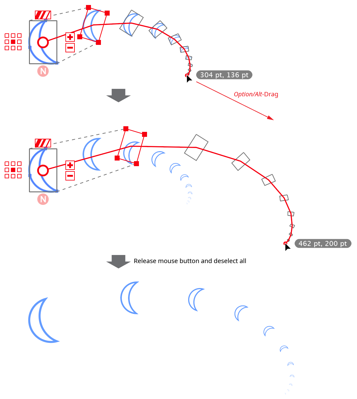
Stylism Transform Copy Chain Drag with Option
Doubleclicking the control brings up a dialog in which the number of copies can be directly entered. If Option/Alt is being held down (so the coordinates of the last copy are displayed), a dialog in which the coordinates can be numerically entered is displayed.
Illustrator Location:
Illustrator Main Menu > Window > Astute Graphics > Phantasm > Curves
Phantasm Curves is a live effect/filter that allows color correction of artwork using a curve, similar to Photoshop. As a live effect, it is accessible through the main menu, under Effect > Phantasm > Curves. It can also be applied directly from the Appearance panel using the “Add New Effect” button at the bottom of the panel, or through the Phantasm panel (see Phantasm: Panel).
After applying the live effect using the menu item (or when clicking on the existing effect in the Appearance panel to edit it), the parameters dialog will appear:
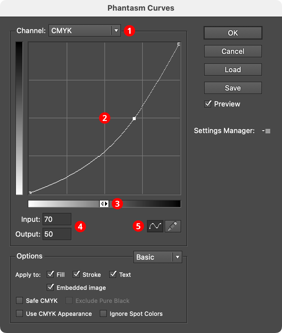
Phantasm Curves Dialog
1. Channel Menu
Specifies which channel or channels the current curve applies to. For CMYK documents, this includes the composite four process colors (CMYK) as well as each individual color. For RGB documents, this includes the composite three primary colors (RGB) as well as each individual color. In both cases, individual spot colors will also appear in the list, as well as Image Alpha, which affects the alpha channel in images with transparency.
Modifying the curve of Image Alpha can be useful for adjusting the output of native live effects which produce an embedded image with transparency, such as Drop Shadow, Outer Glow, and Gaussian Blur:
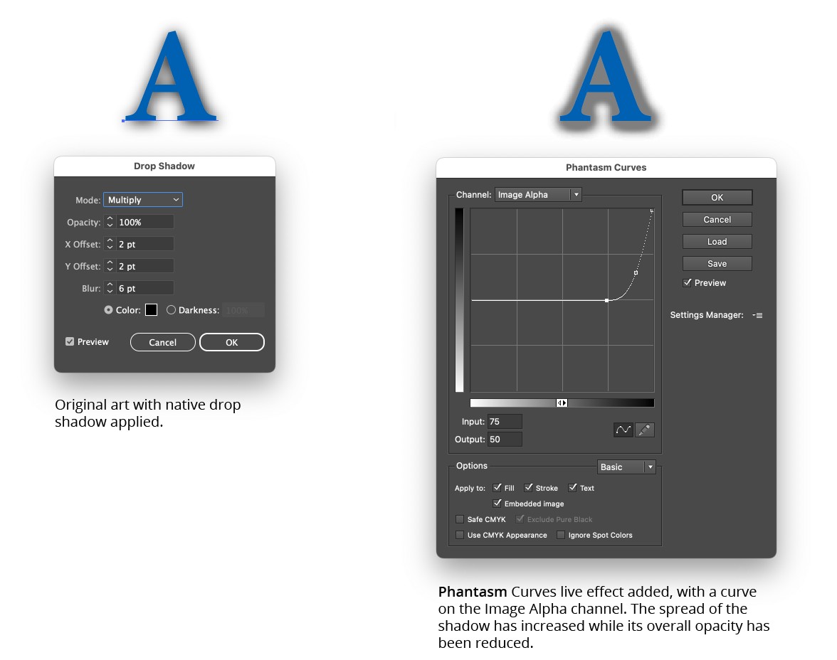
Phantasm Curves Example
2. Curve Graph
The horizontal axis of the graph represents the original brightness values (input levels). The vertical axis represents the new brightness levels (output levels). With the default diagonal line, no colors have been mapped to new values, so all colors have the same input and output values. Nodes on the curve may be moved simply by clicking and dragging them (or their input and/or output values may be modified, see below). A new node may be added by clicking at a spot along the curve which does not already have a node. A node (except the one at the beginning and the one end of the curve) may be deleted by dragging it off the graph area.
By default, the graph has a 4×4 grid, but Option/Alt-clicking on the graph will change the grid to 10×10.
3. Tonal Bar
By default, the graph goes from 0% (white) at lower-left to 100% (black) at upper right, but clicking on the tonal bar icon or the tonal bar itself will switch the graph to go from 0 (black) at lower-left to 255 (white) at upper right.
4. Input/Output levels
These values reflect the selected node, and may be edited to re-position the node.
5. Curve/Map Mode Buttons
By default, the graph is shown as a curve running through individual nodes, but by clicking on the Map button (pencil icon), each point along the axis may be freely drawn on the graph, and may contain discontinuities. Drawing across an existing graph will overwrite the previous lines. If a graph has been drawn in Map mode and the Curve mode button is pressed, Phantasm will approximate the lines as best as it can using a continuous curve. If no nodes are edited and the mode is switched back to Map, the original lines will be restored.
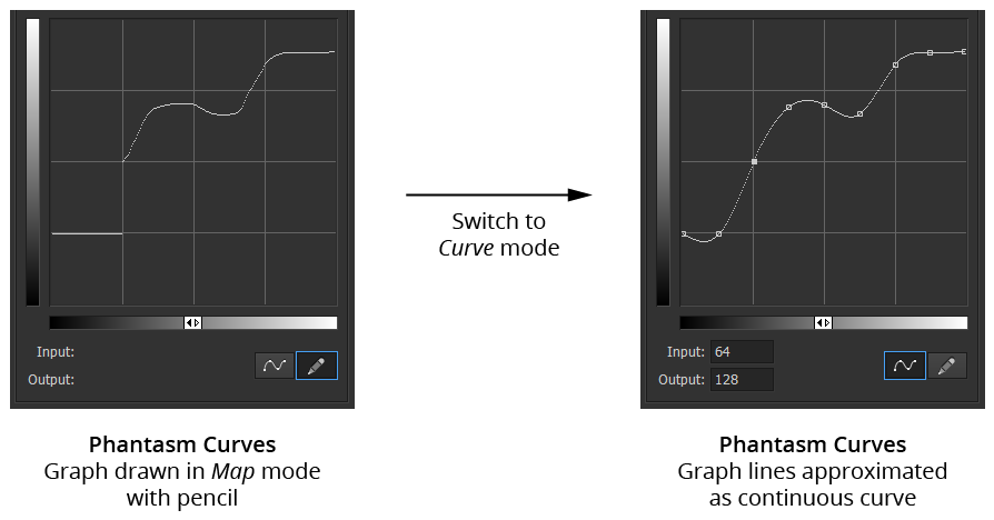
Phantasm Map Mode to Curve Mode
Illustrator Location:
Advanced Toolbar > Stylism Tool
The interactive controls for the native Free Distort live effect consist of a bounding rectangle and two vanishing points:
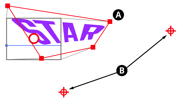
Stylism Free Distort Controls
A. Distorted Object Bounds
The bounds of the object after it has been free distorted are indicated by a red rectangle with nodes at each corner. When the cursor is hovering over a corner node, the corner’s coordinates are displayed. Thin grey lines connect the corners of the rectangle with the original object’s bounds, indicated by a rectangle of solid grey lines. The corner nodes of the distorted object bounds may be dragged to move them (with Shift to constrain the motion to 45° increments around the general constrain angle). The corners will snap to other objects if Smart Guides are enabled; pressing the U key will temporarily toggle the Smart Guides setting. Each corner may also be doubleclicked to numerically enter its coordinates.
The edges may also be dragged to move them.
B. Vanishing Points
If the distorted bounds are configured such that two of the normally parallel edges are no longer parallel, a vanishing point symbol is annotated at the intersection point of their projections (although this may be off the screen). When the cursor is hovering over a vanishing point, the point’s coordinates are displayed, along with dashed lines connecting it to the corresponding edges. The vanishing point may be dragged to reposition it, with Shift used to constrain its motion along one of the edge projections.
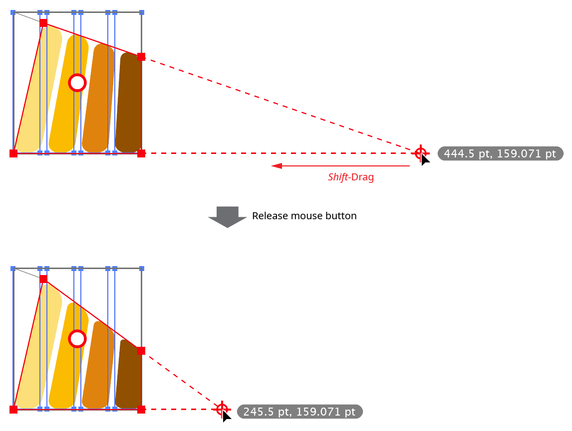
Stylism Free Distort Vanishing Point Drag
Illustrator Location:
Illustrator Main Menu > Window > Astute Graphics > Phantasm > Desaturate
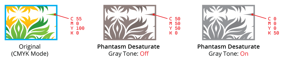
Phantasm Desaturate is a live effect/filter that equalizes color channels. By default, it is the same as using the Hue/Saturation effect with a Saturation value of –100. Note that like Photoshop’s Saturation adjustment, the lightness of the original color is not necessarily preserved. For example, 100% Yellow and 100% Magenta will both be adjusted to a value of 50% Cyan, 50% Magenta, and 50% Yellow.
As a live effect, it is accessible through the main menu, under Effect > Phantasm > Desaturate. It can also be applied directly from the Appearance panel using the “Add New Effect” button at the bottom of the panel, or through the Phantasm panel (see Phantasm: Panel).
After applying the live effect using the menu item (or when clicking on the existing effect in the Appearance panel to edit it), the parameters dialog will appear:
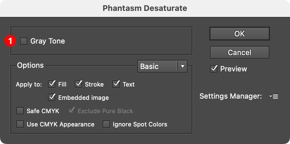
Phantasm Desaturate Dialog
1. Gray Tone
Available only if the document is in CMYK color space. It ensures that the altered color is only composed of Black ink, and it equivalent to using the Hue/Saturation effect in Colorize mode with a Saturation value of 0.
Phantasm Desaturate Example
Illustrator Location:
Advanced Toolbar > Stylism Tool
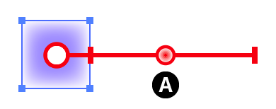
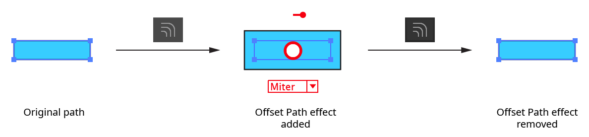
The interactive controls for the native Offset Path live effect consist of a relocatable distance widget and a dropdown menu. For many more options when offsetting a path, including proper offsetting of open paths, as well as multiple offsets, we suggest instead using the Astute Graphics’ AG Offset live effect, which has a dedicated tool and panel.
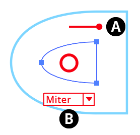
Stylism Offset Path Controls
A. Offset Distance
The length of the widget reflects the offset distance. The “ball” end can be dragged to change the offset value (to the right for positive amounts) or doubleclicked to numerically enter the value. By default, the widget is placed above the center circle. However, it can be repositioned by holding down Option/Alt and dragging the end without the ball. It will snap to the path, which can make adjusting the offset value easier because the widget will be rotated perpendicular to the path, with the offset path therefore passing directly through the ball:
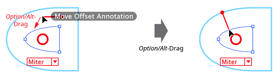
Stylism Offset Path Widget Relocate
B. Corner Type
The dropdown menu specifies the types of corners used when offsetting the path, from among Miter, Round, and Bevel. The rarely-used Miter Limit parameter is not adjustable through the annotated UI.
Illustrator Location:
Illustrator Main Menu > Window > Astute Graphics > Phantasm > Duotone
Phantasm Duotone is a live effect/filter that creates Duotones (or Monotones, Tritones, or Quadtones) from artwork. It is strongly advised that you enable Overprint Preview (in the View menu) before applying the live effect/filter, as it relies on the overprinting of spot colors where applicable.
As a live effect, it is accessible through the main menu, under Effect > Phantasm > Duotone. It can also be applied directly from the Appearance panel using the “Add New Effect” button at the bottom of the panel, or through the Phantasm panel (see Phantasm: Panel).
After applying the live effect using the menu item (or when clicking on the existing effect in the Appearance panel to edit it), the parameters dialog will appear:
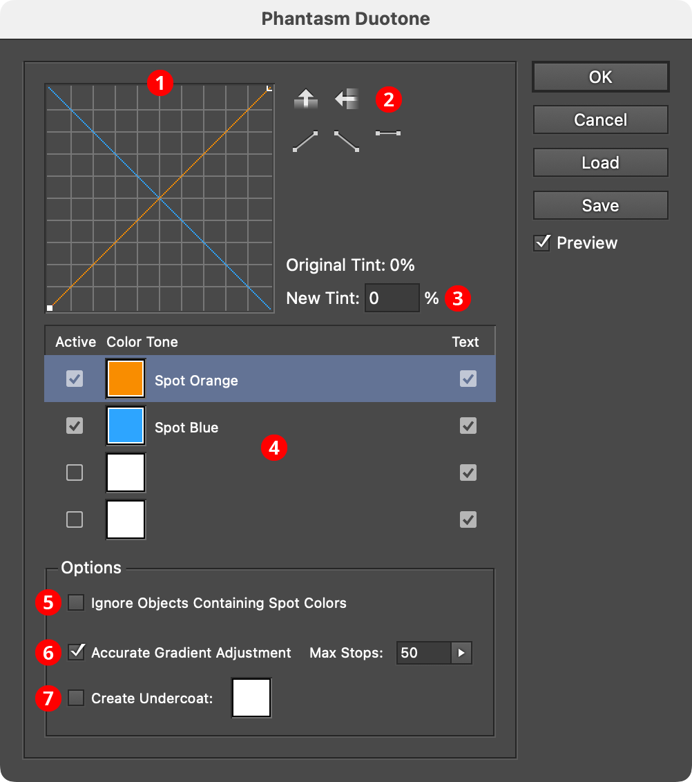
Phantasm Duotone Dialog
1. Color Tone Graph
Shows the relationships between the original tints (shown on the horizontal axis) and the new tints (on the vertical axis) for each color. The graph for the selected color will show nodes, which can be moved (vertically only, as per Photoshop) by dragging them. New nodes can be added by clicking along the curve, but only at horizontal positions where the original tint is a multiple of 10%, plus 5% and 95%. Except for the end nodes, a node can be deleted by dragging it off the graph area.
2. Graph Action Buttons
These five buttons that act to change the selected graph. Flip Vertical and Flip Horizontal flip the graph accordingly; the three lower buttons reset the graph to default linear (0% to 100%), inverse linear (100% to 0%), and full-strength (all 100%), after which it may be edited further as usual.
3. New Tint Input
When a node on a graph is selected, its new tint value (vertical position on the graph) will be displayed here and may be edited numerically.
4. Color Tone List
Shows up to four color tones to use in the effect. Although the color tones are typically spot colors, they may also be process colors (in which case the Multiply transparency effect is used to combine the different tones). The selected color tone in the list is highlighted in a gray-blue; only the selected color tone’s graph is active above and may be edited.
Active Checkbox: Specifies whether a given color tone is part of the effect. If only a single color is active, the result will be a Monotone; if two are active, a Duotone, and so on.
Color Chip: May be clicked to select a new color through the color picker dialog. However, this dialog does not provide for creating new spot colors so these should be created in the normal way on the Swatches panel before applying the Duotone filter or effect. If a new process color is created, it may be renamed by
doubleclickingon the color name in the Color Tone List.Text Checkbox: Specifies whether any editable text present in the selection is rendered in that tone. This can allow users to ensure registration problems are avoided with text by limiting the number of tones in which the text is rendered. Care should be taken when using this option, as various scenarios could mean the text vanishes beneath another color tone.
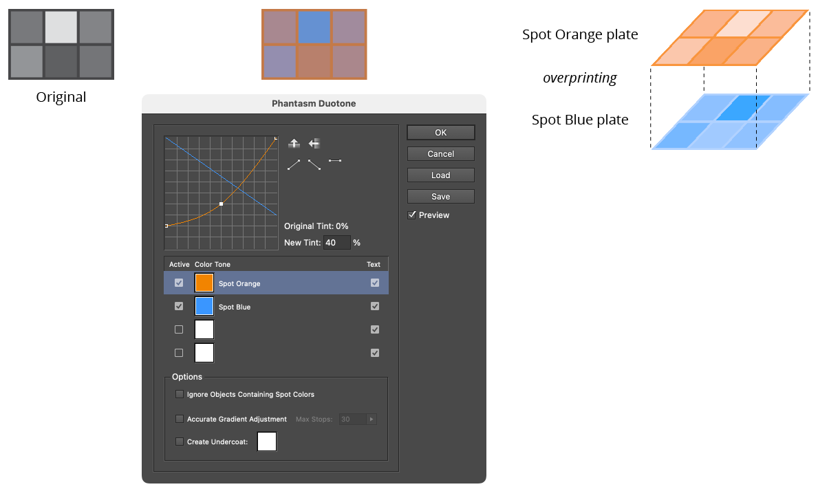
Phantasm Duotone Example
5. Ignore Objects Containing Spot Colors
When enabled, any objects or groups in the selection which contain objects defined with spot colors will not be rendered as a duotone.
6. Accurate Gradient Adjustment
Acts as per other Phantasm effects (See Phantasm: Common Options (Advanced)).
7. Create Undercoat
When enabled, creates a solid, opaque, “undercoat” color for blocking out any underlying artwork which might normally show through due to overprints being added. White is most commonly used as the undercoat color, but it can be changed by clicking on the color chip to bring up the standard color picker dialog.
Illustrator Location:
Advanced Toolbar > Stylism Tool
The interactive controls for the native Gaussian Blur consist of a single slider.
Stylism Gaussian Blur Controls
A. Blur Slider
The blur slider thumb control may be dragged along the blur arm to change the Gaussian blur radius, between 0.1 and 250 pt. The value increases away from the center circle. When the cursor is hovering over the control or dragging it, the current blur radius is displayed. The blur slider can also be clicked anywhere along its length to move the blur thumb immediately to that position. While dragging the blur slider, in addition to the common keypresses (see Stylism Annotated Controls and Common Drag Keypresses), the following keypresses can be used:
Shift: Constrains the blur radius to integer values.
Doubleclicking the control brings up a dialog which allows you to enter the blur radius numerically.
If the blur radius is increased to a value that exceeds the native Document Raster Effects Setting “Add [X] Around Object”, by default this setting will automatically be increased to avoid clipping, and a warning dialog will be shown:
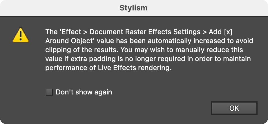
Stylism Raster Effects Around Object Warning
Illustrator Location:
Illustrator Main Menu > Window > Astute Graphics > Phantasm > Exposure
Phantasm Exposure is a live effect/filter that implements the Photoshop “Exposure” adjustment for artwork. As the tool was originally developed for adjusting the tone of HDR RGB images, results may be slightly different when used in CMYK color mode.
As a live effect, it is accessible through the main menu, under Effect > Phantasm > Exposure. It can also be applied directly from the Appearance panel using the “Add New Effect” button at the bottom of the panel, or through the Phantasm panel (see Phantasm: Panel).
After applying the live effect using the menu item (or when clicking on the existing effect in the Appearance panel to edit it), the parameters dialog will appear:
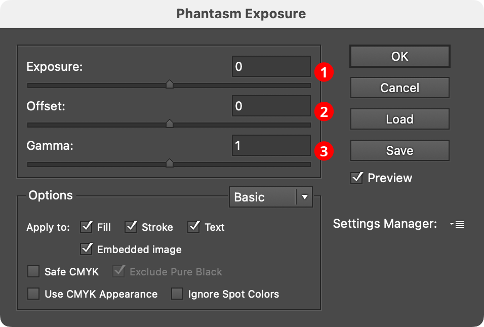
Phantasm Exposure Dialog
1. Exposure
Adjusts the highlights, largely maintaining the deepest shadows. It can range from –20 to 20.
2. Offset
Controls the shadows and midtones, with little effect on the highlights. It can range from –0.5 to 0.5.
3. Gamma
Controls the gamma level. It can range from 9.99 to 0.01; a value of 1 equates to no adjustment.
Illustrator Location:
Illustrator Main Menu > Window > Astute Graphics > Stylism
The menu item to show and hide the Stylism panel can be found in the main menu under Window > Astute Graphics > Stylism.
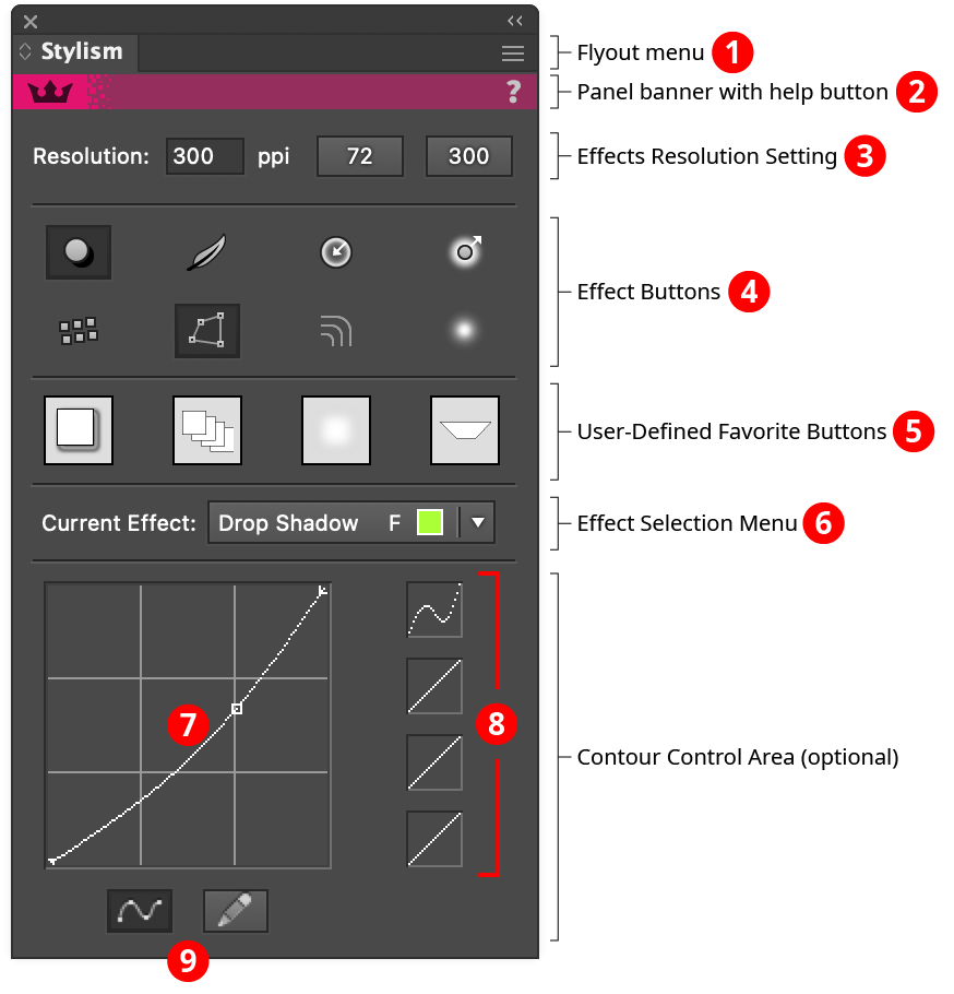
Stylism Panel
1. Flyout menu
See Stylism Panel: Flyout Menu.
2. Panel banner
The Stylism panel banner has a help button on the right which opens the help documentation in the Astute Manager. If this does not automatically appear, please ensure your Astute Manager is running first. Along with the rest of the panel, the panel banner can be clicked to activate the Stylism tool. This is a quick method of locating the tool within the default Advanced toolbar or a custom toolbar.
3. Effects Resolution Setting
This area allows you to see and quickly change the Document Effects Raster Resolution setting, the resolution at which raster objects produced through live effects (such as Drop Shadow, Feather, Gaussian Blur, etc.) are created. Natively, this is found under the dialog opened through the menu item Effect > Document Raster Effects Settings.... Typically, the resolution is set to a fairly low value (for example, 72 ppi) while working on the document, for speed. Then, when the document is ready to go to print, it is changed to higher resolution (typically 300 ppi or more), for quality.
The new resolution can be entered into the input box, or one of the buttons on the right can be clicked. To customize the resolutions produced by either button, hold down Option/Alt when clicking it.
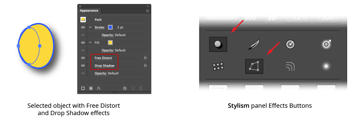
4. Effects Buttons
The effects buttons are used to quickly add and remove the eight supported native live effects from the targeted art simply by clicking on them (clicking once adds the effect; clicking again removes it).
Stylism Panel Effects Buttons Basics
Buttons which are selected (dark) indicate that its effect is present. The buttons in the first row represent (from left to right): Drop Shadow, Feather, Inner Glow, and Outer Glow; those in the second row represent Transform, Free Distort, Offset Path, and Gaussian Blur.
Stylism Panel Effects Buttons
Effects are added in their default positions (below all strokes and fills, except for the Offset Path effect, which is added above all strokes and fills) and always start with a default set of parameters. Initially, these are the same parameters that would be set when adding the effect natively through the Effect menu. For example, a Drop Shadow is initially given X and Y offsets of 7 pt, a blur of 5 pt, and an opacity of 75%.
However, you can change the parameters that are initially applied when the effect is added using one of the Stylism effects buttons (or flyout menu). To do this, select a single object that has the effect and change its parameters to the desired settings. Then, hold down Option/Alt and click the corresponding effects button. From then on, using the button will add the effect with your custom parameters. (The buttons can have their Illustrator-specified default parameters restored by using the panel flyout menu item Reset All Standard Effects).
Normally, if an effect is already present, then clicking the corresponding effects button again will remove it. To instead add a second copy of the effect, hold down Shift when clicking the button.
Holding down Command/Ctrl when clicking a selected effects button is a shortcut for making it the current effect.
5. User-Defined Favorite Buttons
The user-defined favorite (“UDF”) buttons allow you to save the look of one or more Stylism-controlled effects and later apply it to selected objects. Like a native Graphic Style when using its merge mode, the effects in the UDF buttons do not replace the object’s current appearance but instead add to it. User-
defined favorites are available across documents and Illustrator sessions.
To define a UDF button, there must be only one object selected, and it must contain at least one effect from the eight native effects that Stylism controls. Then, hold down Option/Alt and click the button. The thumbnail image in the button will update, showing the effect(s) as applied to a small square with a white fill and black stroke. Now, clicking the button will add those effect(s) to any selected art without affecting any existing effects. The Stylism tool will be automatically made active (if it is not already).
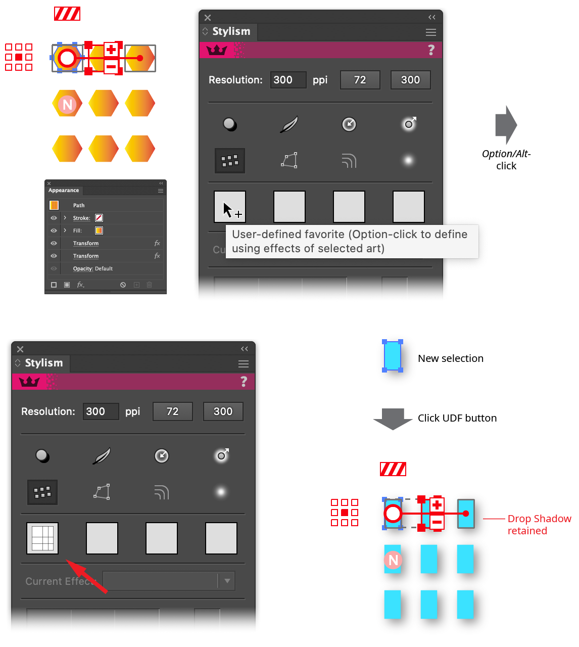
Stylism Panel User Defined Button Usage
If the selected art already contains the same live effect in the same position as one defined in the UDF button, it will not be replaced. If the UDF button had an effect applied in a stroke or fill and the receiving object has no strokes or fills, the effect will instead be added in its normal position.
6. Effect Selection Menu
This menu is used to switch the current effect (the effect for which the Stylism tool is displaying an annotated UI) when the selected art contains more than one effect, including multiple copies of a single effect. Each effect that is present is listed by name in the menu. Following the name is a code for its position in the appearance stack (as viewed in the Appearance panel):
a. Pre: Effect is above any strokes or fills.
b. S: Effect is in a stroke.
c. F: Effect is in a fill.
d. Post: Effect is below any strokes or fills.
For effects contained in strokes and fills, a small swatch of the color of the stroke or fill is also displayed, to make it easier to select the correct effect.
7. Contour Graph
This graph is available when the Contour Control area is showing, the Stylism tool is selected, and the Astute Graphics’ Phantasm plugin is installed. For use with effects which create an image with an alpha mask (Drop Shadow, Feather, Outer Glow, and Gaussian Blur), it allows you to put a curve on the alpha channel (implemented by automatically adding a matching Phantasm Curves live effect at the bottom of the effect stack). This is most commonly used with the Drop Shadow effect, to achieve a look that can’t be made through changes to the Drop Shadow parameters alone.
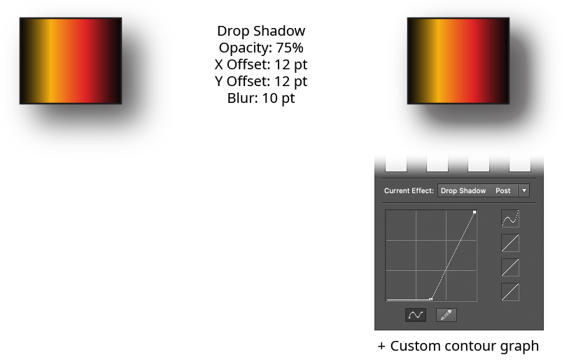
Stylism Contour Control Example
The horizontal axis represents the input alpha value, while the vertical axis represents the output value. With the default diagonal line, the two are the same. Nodes on the curve may be moved simply by clicking and dragging them. A new node may be added by clicking at a spot along the curve which does not already have a node. Nodes (except the ones at the beginning and the end of the curve) may be deleted by dragging them off the graph area.
8. Contour Graph Curve Preset Buttons
These four buttons allow you to load and store contour graph curves. Each displays a thumbnail of the curve it contains. To load a graph, simply click on a button. To store the current curve to a button, hold down Option/Alt and click on a button. Curve presets are preserved across Illustrator sessions.
9. Contour Graph Mode Buttons
The contour graph can be created using one of two modes. The left-hand “Curves” button allows editing it as a smooth curve passing through two or more nodes. The right-hand “Pencil” button allows drawing freehand, with the ability to change each value arbitrarily. If a graph is started in pencil mode and later changed to curves mode, the best possible curve will be fitted through the points.
Illustrator Location:
Illustrator Main Menu > Window > Astute Graphics > Phantasm > Halftone
Phantasm Halftone is a live effect/filter that converts artwork into a vector halftone pattern. It includes numerous options and adjustments, including full separation control, dot gain adjustment, a range of dot patterns and types, and the ability to save and recall custom halftone effects.
As a live effect, it is accessible through the main menu, under Effect > Phantasm > Halftone. It can also be applied directly from the Appearance panel using the “Add New Effect” button at the bottom of the panel, or through the Phantasm panel (see Phantasm: Panel).
After applying the live effect using the menu item (or when clicking on the existing effect in the Appearance panel to edit it), the parameters dialog will appear:
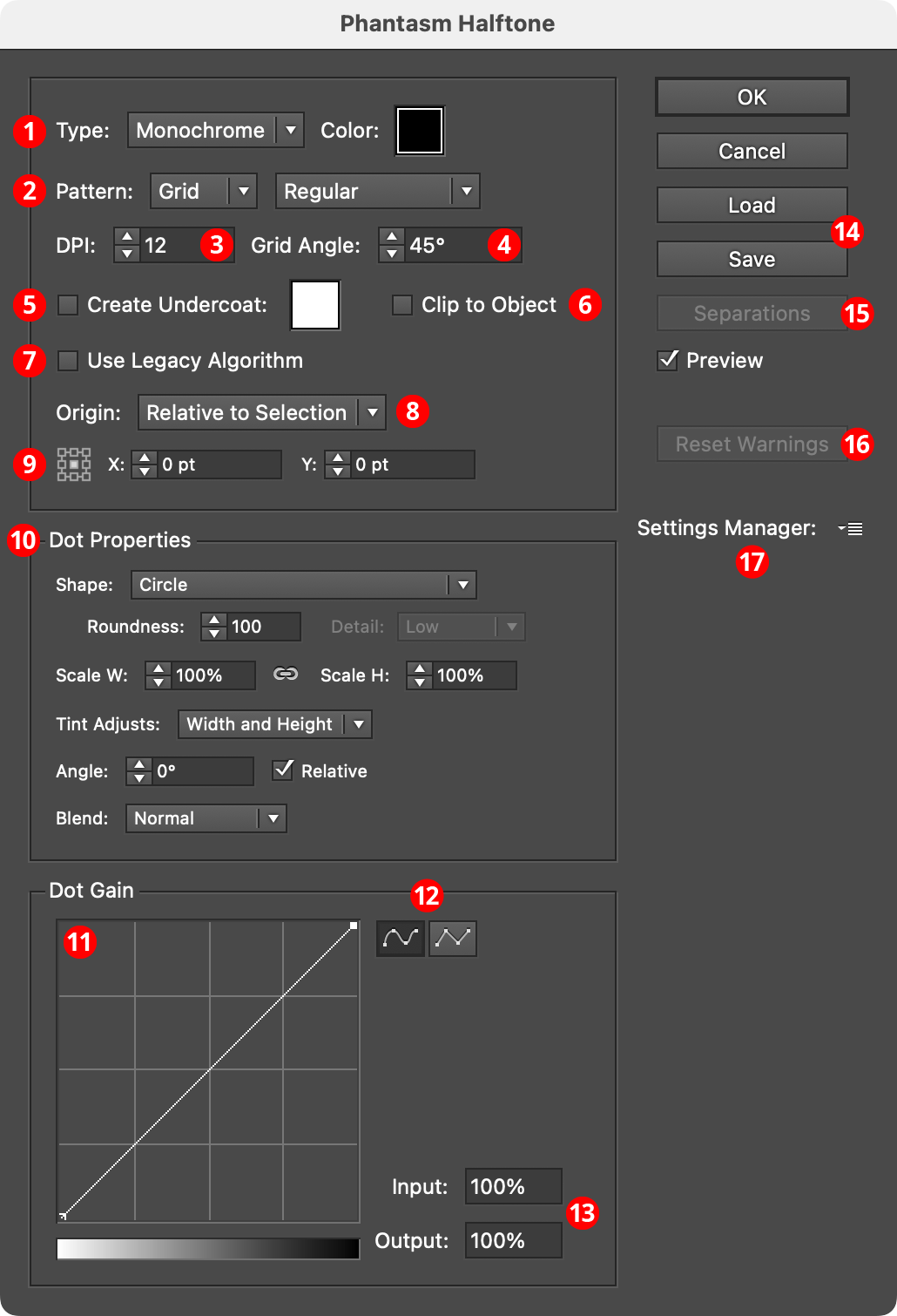
Phantasm Halftones Dialog
1. Type
Specifies the type of halftone:
Monotone: The halftone will be created using one layer of dots, all of the same color. Their sizes are (by default) based on the grayscale equivalent of the underlying artwork. Dot color may be specified by clicking on the color chip to bring up the native color picker dialog.
CMYK: Available when the document is in CMYK color mode. The halftone will be created using four layers of dots, each using one of the process colors (spot colors present in the artwork will add additional dot layers). Their sizes are (by default) based on the CMYK value at each dot’s position in the underlying artwork. By default each dot layer will have its blend mode set to Multiply. If the Sample Tint option is enabled, the grayscale equivalent of the artwork at each dot location is used to set the tint of the dot’s color.
RGB: Available when the document is in RGB color mode. The halftone will be created using three layers of dots, each using one of the primary colors (spot colors present in the artwork will create additional dot layers). Their sizes are (by default) based on the RGB value at each dot’s position in the underlying artwork. By default each dot layer will have its blend mode set to Screen. If the Sample Tint option is enabled, the grayscale equivalent of the artwork at each dot location is used to set the tint of the dot’s color.
Sampled: The halftone will be created using one layer of dots. Each dot’s color will be picked up from the underlying artwork.
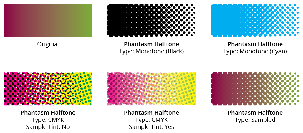
Phantasm Halftone Type Examples
2. Pattern
Specifies the pattern of the dots:
Grid: The dots are placed on a square grid. If the pull-down menu is set to Alternating, the grid cells are staggered, like rows of bricks.
FM: A specialized type of pattern (short for Frequency Modulated); it has the subtypes Floyd-Steinberg (a pseudo-random pattern) and Bayer Dither (a fixed pattern).
Radial: The dots are placed in concentric circles. The number of “spokes” is specifiable, from 5 to 7, where spokes refers to the number of dots in the first circle.
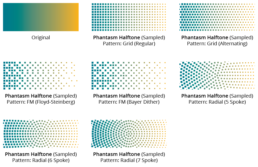
Phantasm Halftone Patterns
3. DPI
Short for dots per inch; specifies the dot size, measured as the distance between dots in inches. Values can range between 0.01 and 600. Higher DPI settings may create tens or even hundreds of thousands of dots, with potential very long processing times. A warning dialog will appear if this is the case:
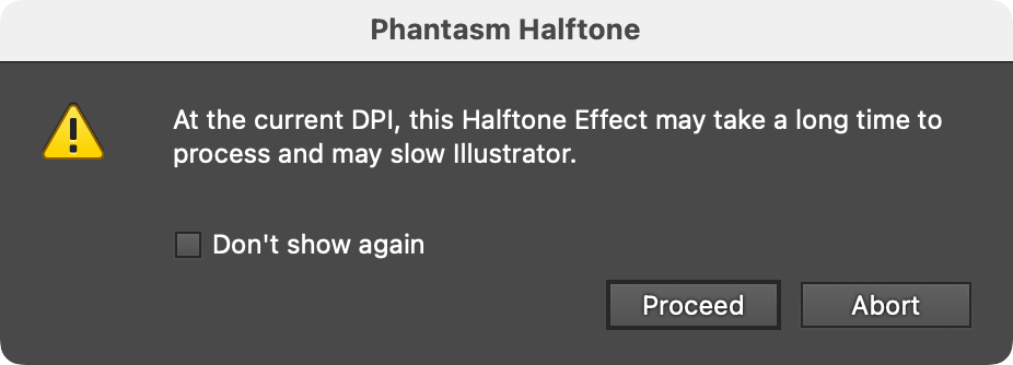
Phantasm Halftone Slow Processing Warning Dialog
Clicking Abort will keep the halftone from being calculated, but the effect will still be attached to the artwork, and if it or the artwork is edited, the effect will need to be re-calculated and thus the warning will re-appear (unless the Don’t show again setting has been enabled).
4. Grid Angle
Rotates the halftone effect relative to the page. When operating with separations (i.e., the halftone Type is CMYK or RGB), each channel’s angle is set relative to the overall Grid Angle.
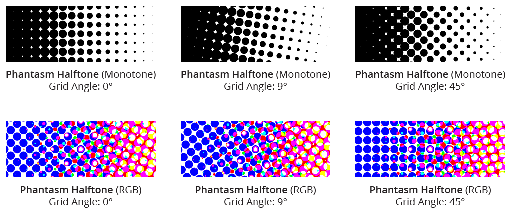
Phantasm Halftone Grid Angle Example
5. Create Undercoat
When enabled, creates a solid, opaque, “undercoat” color for blocking out any underlying artwork which might normally show through when the halftone dots are being created using transparency or overprints. White is most commonly used as the undercoat color, but it can be changed by clicking on the color chip to bring up the standard color picker dialog.
6. Clip to Object
When enabled, all halftone dots are placed inside a clipping mask so they will never protrude beyond the edges of the original artwork.
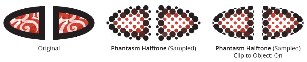
Phantasm Halftone Clip to Object Example
7. Use Legacy Algorithm
With Phantasm version 4.0.0, the algorithm which determines the size of the dots near the edges of the object was changed to better reflect an anti-aliased appearance, and to reduce the number of awkwardly-placed full-sized dots. However, the legacy algorithm may still be used by enabling this option, and it can still be useful for infographics or when used with Clip to Object.
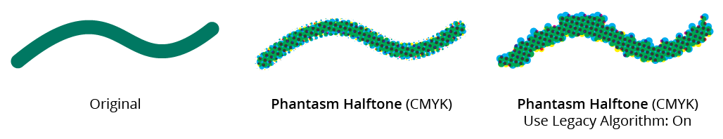
Phantasm Halftone Legacy Algorithm
8. Origin Position
Each halftone grid has an origin, from which the positions of all the dots are calculated (this is most apparent with Radial pattern halftones). By default, the origin is positioned relative to the selection artwork, but, for example, when halftones on different objects need to align regardless of how the objects are moved, it is more appropriate to align the halftone relative to the artboard.
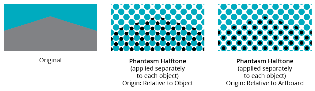
Phantasm Halftone Origin Position
9. Origin Specification
The position of the origin (relative to either the Selection or the Artboard) can be fine-tuned with the nineblock control (to specify Center, Top Left, Bottom Middle, etc.) as well as the X- and Y-offset values, which can be either positive or negative.
10. Dot Properties
By default, the dots used in the halftones are simple circles. However, the Shape pulldown menu offers a range of alternative options for dot shapes. When the Shape is changed, the upper part of the Dot Properties section of the dialog may re-configure itself with alternate or additional controls, as shown below.
11. Dot Gain Graph
The Dot Gain graph allows for precise control of the halftone’s response to tonal changes by allowing a non-linear relationship between the underlying grayscale tone and the dot scaling. This provides the ability to darken or lighten the overall results and can be invaluable when dealing with alternative dot shapes like characters and symbols.
The horizontal axis represents the underlying grayscale-equivalent tone of the artwork, from 0% to 100%, while the vertical axis represents the scaling of the dots (which is in addition to the overall Scale H and Scale V values), also from 0% to 100%. With the default diagonal line, the relationship is linear; that is, the scaling of each dot is equal to the underlying tone. Nodes on the curve may be moved simply by clicking and dragging them (or their input and/or output values may be modified, see below). A new node may be added by clicking at a spot along the curve which does not already have a node. Nodes (except the ones at the beginning and the end of the curve) may be deleted by dragging them off the graph area.
By default, the graph has a 4×4 grid, but Option/Alt-clicking on the graph will change the grid to 10×10.
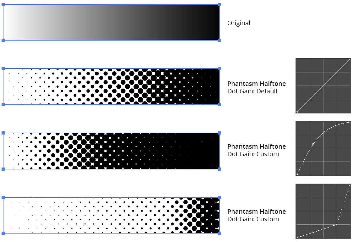
Phantasm Halftone Dot Gain Examples
12. Dot Gain Graph Smooth/Linear Buttons
By default, nodes on the dot gain graph are connected by smooth curves, but by clicking the Linear Segments button, they will instead be connected by straight lines, allowing the curve to change direction abruptly at a node.
13. Input/Output Values
When hovering over the graph, the input and output values corresponding to the cursor location are displayed. When a node of a graph is selected, the values are editable, and may be changed to move the node numerically.
14. Load/Save Buttons
Provide a means to save (or load) all of the current Phantasm Halftone settings to/from an external file, which may be shared with other users. Clicking on either the Load or Save buttons will open the standard operating system’s file load/save dialogue. The file type is of .PHT type.
15. Separations Button
Available when the halftone type is CMYK or RGB. Clicking the button brings up the Separations dialog, in which the visibility, order, angle, origin, and offset of each separation may be edited.
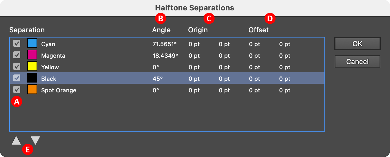
Phantasm Halftone Separations Dialog
A. Visibility Checkbox: Disabling the checkbox will hide that separation in the halftone.
B. Angle: The angle of the halftone for each channel (relative to the overall grid angle). When clicked, the Edit Separation dialog is shown, where the value may be changed. Note that the artwork will not update (even with Preview enabled) until the OK button is clicked.
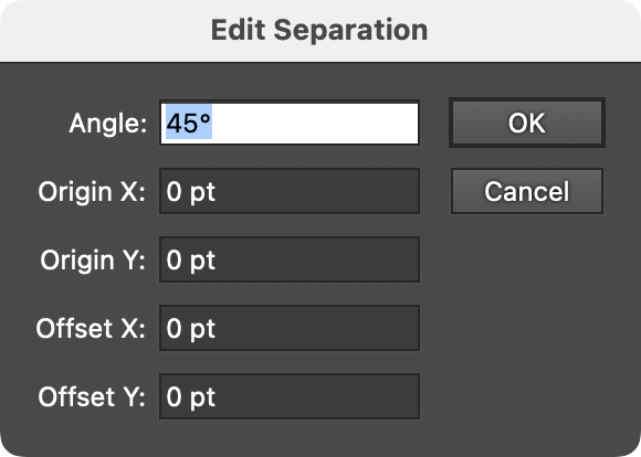
Phantasm Halftone Edit Separations Dialog
C. Origin: The origin of the halftone for each channel (relative to the overall grid origin). When clicked, the Edit Separation dialog is shown, where the value may be changed.
D. Offset: The distance that the halftone dots for a specific separation will be shifted after they have been composed using the underlying art. When clicked, the Edit Separation dialog is shown, where the value may be changed. Adding an offset can be useful for simulating printing press misregistration:
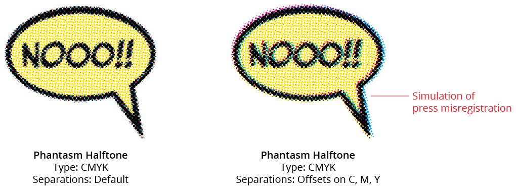
Phantasm Halftone Separations Offsets
E. Move Up/Move Down Buttons: With a separation selected, clicking one of the buttons will move it up or down in the stacking order. Generally, when the halftone blend mode is set to Transparency or Overprint, this will have no visible effect.
16. Reset Warnings Button
If a warning dialog (such as the long processing time warning) has been hidden through the Don’t show again checkbox, this button will reset all warnings so they appear again.
Illustrator Location:
Illustrator Main Menu > Window > Astute Graphics > Perturb
The Perturb Live Effect may be applied both through the main menu (Effect > Randomino > Perturb...) as well as through the Perturb panel, which will appear in the main menu under Windows > Astute Graphics > Perturb:
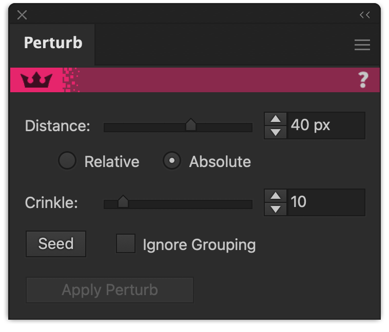
Randomino's Perturb Panel
The Perturb panel is used in conjunction with the Perturb live effect, which allows you to independently move anchor points in the selected art in a random manner.
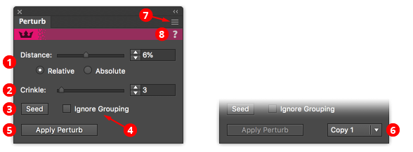
Perturb Panel Callouts
1. Distance controls
The maximum distance that each anchor point will be shifted (in a random direction); it may be adjusted with the slider or by typing a value into the input box. In Relative mode, the value is a percentage of the size of the object (as measured by the diagonal of its bounding box). In Absolute mode, it is a value in the current document units that does not depend on the path’s size.
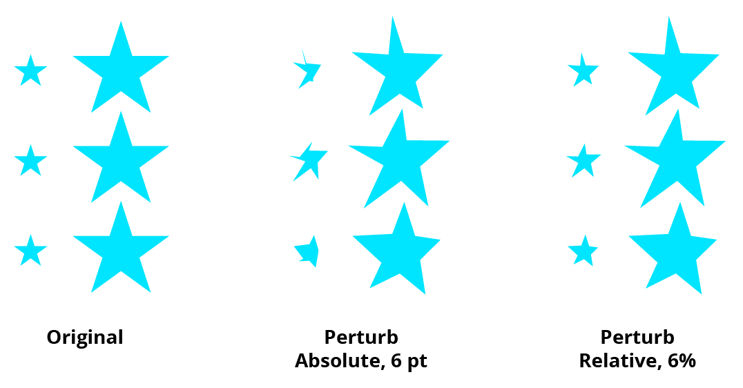
Perturb Panel Distance Settings
2. Crinkle Controls
In general, Perturb is best for subtly changing paths; the distance parameter should be set to a value lower than the closest anchor points in the original paths. Otherwise, path segments can cross and the results are generally not desirable. However, the Crinkle parameter attempts to allow for higher distance values. When the Crinkle value is low, the closer each object’s anchor points are to each other, the more similarly they will be moved. This allows distortion of an entire shape without losing fine details within the shape. Regardless of Crinkle value, points that are coincident will be moved identically.
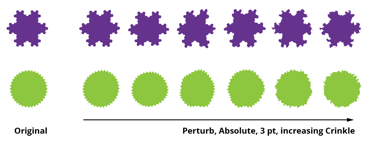
Perturb Panel Crinkle Settings
3. Seed Button
Changes the random seed. Each seed value creates a specific set of random values which Perturb uses to offset the points. When applying the Perturb effect to multiple copies of one object, they will initially have the same seed and therefore look the same. Clicking the seed button will give each a new seed. To view the seed value or to set a specific seed value, Option/Alt-click the button.
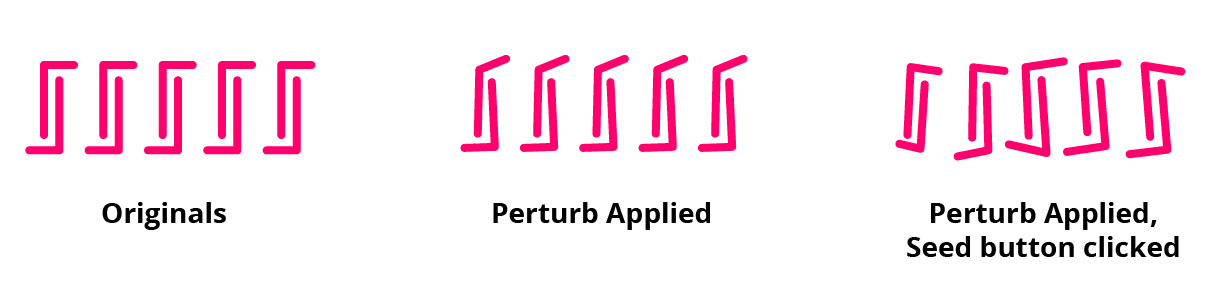
Perturb Panel Seed Settings
4. Ignore Grouping checkbox
When this preference is enabled, grouped objects will be treated as if they were ungrouped. Coincident points of different paths in the group will no longer be locked together.
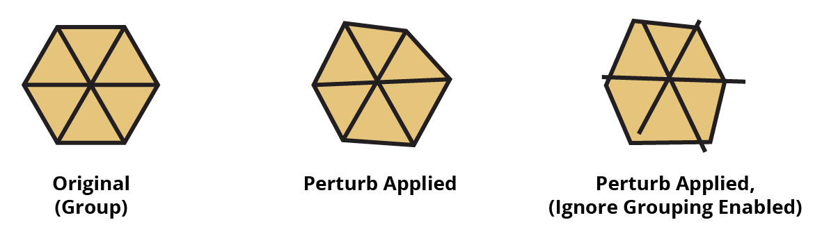
Perturb Ignore Grouping Option
5. Apply button
Click to apply the Perturb effect to the selected artwork. To apply multiple Perturb effects to a single piece of artwork, use the main Illustrator menu item Effect > Randomino > Perturb..., or Option/ Alt-drag the Perturb effect in the Appearance panel. For example, the stroke and the fill of a path could be independently Perturbed.
6. Copy popup menu
Chooses which Perturb effect to edit, when the selected artwork has multiple Perturb effects.
7. Flyout menu
Removes all top-level Perturb effects from the selected artwork. Note that if a Perturb effect is applied to an individual member of a group and the entire group is selected, the menu item will not be available.
8. Panel banner
The help button on the right opens the help documentation in the Astute Manager. If this does not automatically appear, please ensure your Astute Manager is running first.
Illustrator Location:
Illustrator Main Menu > Window > Astute Graphics > Phantasm > Halftone
When the dot shape is set to Circle, the Dot Properties area is configured as follows:
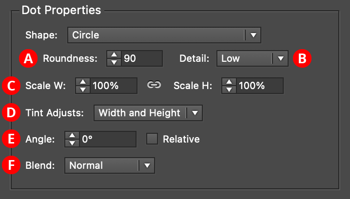
Phantasm Halftone Dot Properties - Circle
A. Roundness
Ranges from 0 to 100, with 100 corresponding to perfect circles. Lower values simulate the appearance of real halftone dots printed with ink on paper, with edges that are never perfectly smooth.
B. Detail
For Roundness less than 100, qualitatively specifies the number of anchor points used to describe the shape. Detail can be either Low, Medium, High, or Very High.
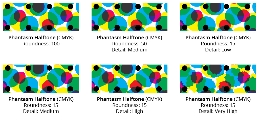
Phantasm Halftone Roundness Detail
C. Scale
Specifies the maximum size of the dot as a percentage (from 1% to 1000%) of the full coverage size. The full coverage size is set such that the dot leaves no gaps when applied to a 100% Black area. By unlinking the Width and Height inputs, the aspect ratio of the dots may be changed. For example, a circle may be transformed into an ellipse.
D. Tint Adjusts
By default, all dots have both their width and height adjusted based on the sample tint value. This is, after all, the very definition of halftoning. However, for special effects, the pull-down menu can be changed so only the Width is adjusted, or only the Height, or neither. The None setting is often useful when using a Sampled type halftone, since the dot’s color already reflects the underlying tint and therefore doesn’t need to get smaller to become lighter.
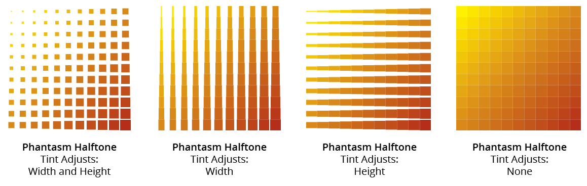
Phantasm Halftone Tint Adjusts
E. Angle
The angle with which to rotate the halftone dot. If the Relative checkbox is enabled, then the angle is relative to the angle of the entire halftone grid.
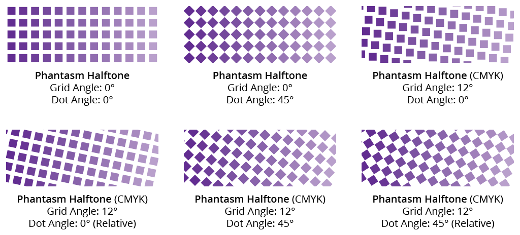
Phantasm Halftone Dot Angle
If the dot shape is set to Circle, changing the dot angle will not result in any visible change, but the placement of the anchor points on each circle is being affected and would be apparent if the appearance were expanded.
F. Blend
The blend mode to use on the halftone dots. The default for Monotone and Sampled halftone types is Normal (resulting in opaque dots), since there is only one layer of dots. Otherwise, the default mode is Transparency, either as Multiply transparency for CMYK documents or Screen transparency for RGB documents.
CMYK type halftones offer a third blend option: Overprint. To properly view halftones using the Overprint blend mode, Overprint Preview (from the View menu) needs to be enabled. This blend mode is recommended if the resultant artwork is destined to be used in commercial offset printing, as it correctly retains original spot color information.
When the blend mode is set to Transparency or Overprint, it may be desirable to opt for Create Undercoat if there is underlying artwork which has not been changed to a halftone effect. This would block out the underlying artwork from showing through.
Illustrator Location:
Illustrator Main Menu > Effect > Randomino > Color Randomizer...
Color Randomizer is an Astute Graphics live effect for randomly and non-destructively varying the hue, saturation, and/or lightness of one or more objects. Both linear and Gaussian random distributions are supported, and the variation amounts can be quantized to a specific number of distinct values. Objects can be “filtered” so only some of them are affected, and, when applying the effect to nested groups, the depth at which it is applied can be specified.

Color Randomizer Example
As with most live effects, Color Randomizer appears in the main menu, under Effect > Randomino. It can also be applied directly from the Appearance panel using the “Add New Effect” button at the bottom of the panel.
Color Randomizer Parameters Dialog
After applying the live effect using the menu item (or when clicking on the existing effect in the Appearance panel to edit it), the parameters dialog will appear:
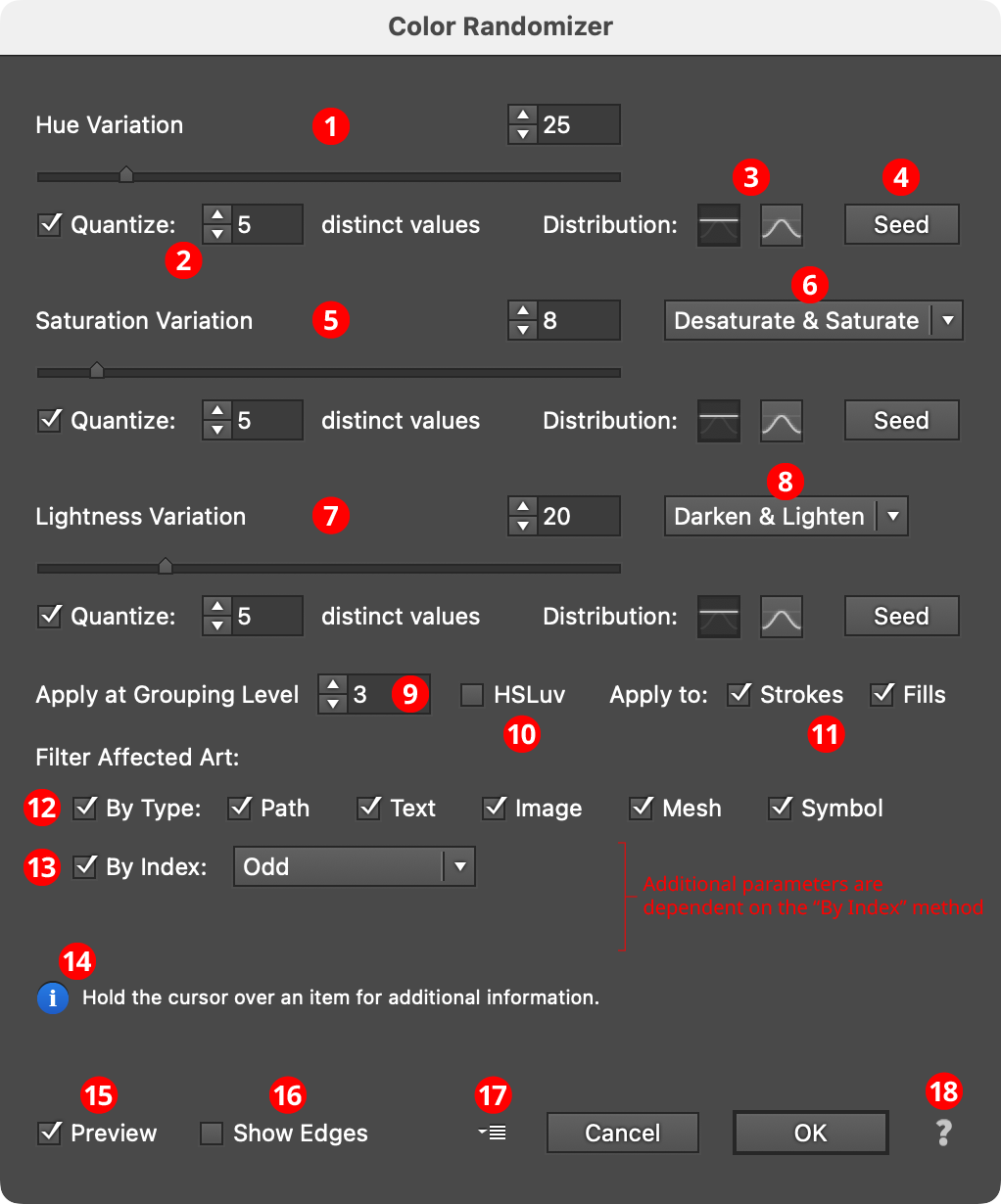
Color Randomizer Parameters Dialog
1. Hue Variation
The amount of variation in hue to apply, ranging from 0 (no variation) to 180 (maximum variation). The value can be changed with the slider or entered numerically in the text box.
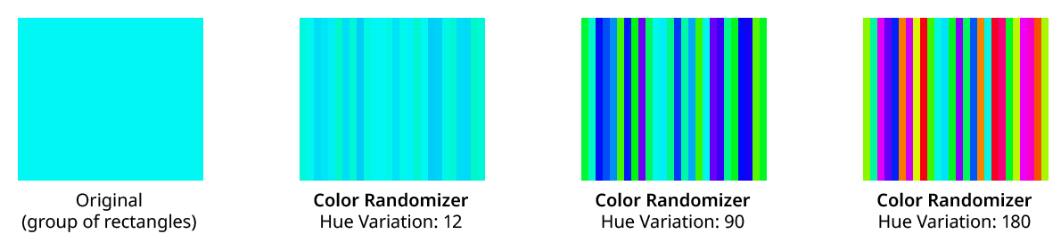
Color Randomizer Hue Variation Examples
Variation values are equivalent to moving in both directions the specified angle away from the original hue around the color wheel. The full wheel is 360°, so a variation of 90 would move 90° or one-quarter of the way, in each direction around the wheel. Any hue between these two end colors may be randomly picked.
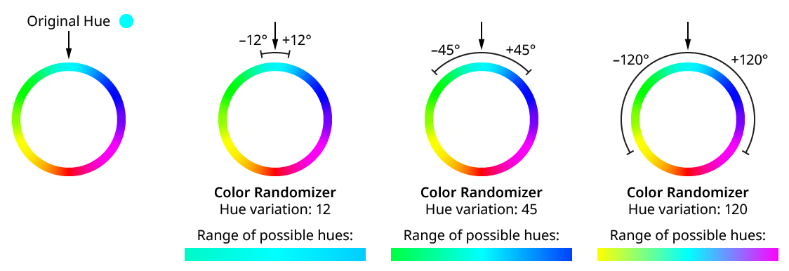
Color Randomizer Hue Variation
2. Quantize
Reduces the range of random variation values so only the specified number of distinct values are produced. For example, a hue variation of 45 would normally produce any value between –45 and 45 — say, 17.63. However, with Quantize turned on and 5 distinct values, the only values that will result are –45, –22.5, 0, 22.5, and 45. Quantized values always include the two end values with some number of evenly-spaced values in between.
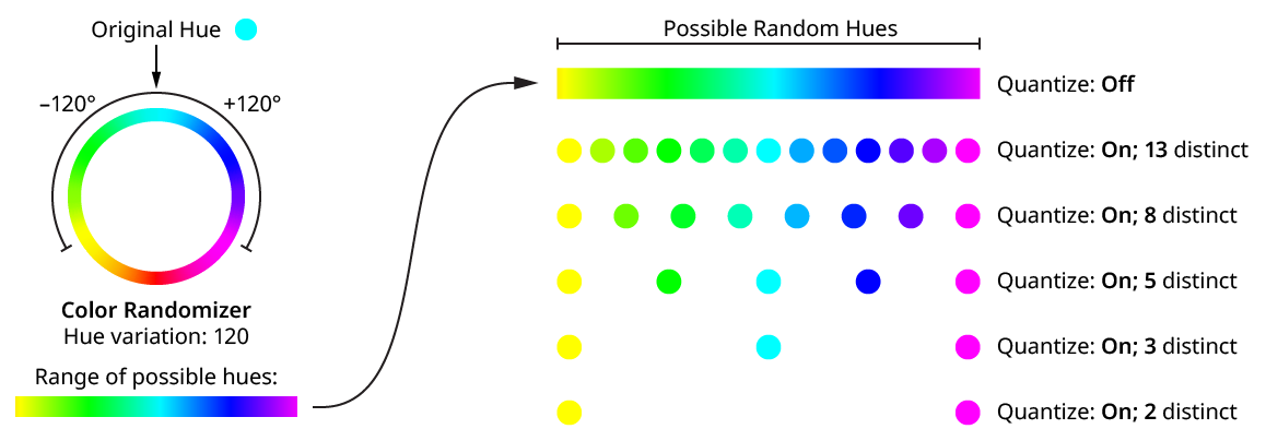
Color Randomizer Hue Variation Quantize
Note that when using a variation of 180 or close to it, the two end values result in the same or roughly the same hue (since they are both halfway around the color wheel, though in opposite directions), so the number of distinct values will appear to be one fewer than specified.
Using the HSLuv color space (see below) changes the way hue and saturation changes are made.
3. Distribution Curves
Specifies either a linear distribution in random values (all values in the range are equally likely to be chosen) or a Gaussian distribution (central values in the range are more likely to be chosen).
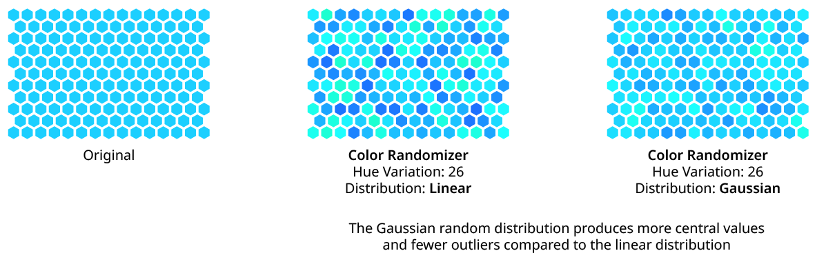
Color Randomizer Distribution
4. Seed
Each random seed number leads to a different sequence of random values. Clicking the button picks a new seed, thereby changing the look of the artwork. To view or specify the seed number directly, Option/Alt-click the button. This lets you recreate a previously-generated look.
5. Saturation Variation
The amount of variation in color saturation to apply, ranging from 0 (no variation) to 100 (maximum variation). Saturation changes are made in the same way that Photoshop and the Phantasm plugin calculates them (unless the HSLuv color space is being used; see below).
6. Saturation Direction
The dropdown menu specifies whether the saturation variation applies in both the negative and positive directions (Desaturate & Saturate), or in just one direction (Desaturate Only or Saturate Only).
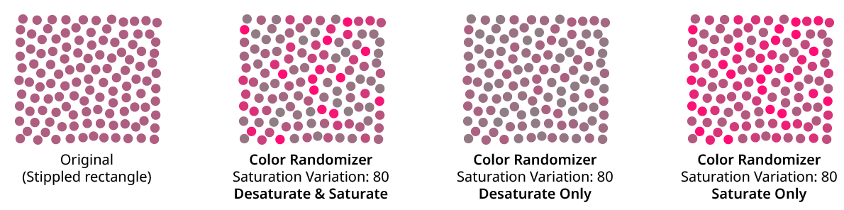
Color Randomizer Saturation Variation Examples
7. Lightness Variation
The amount of variation in lightness to apply, ranging from 0 (no variation) to 100 (maximum variation).
8. Lightness Direction
The dropdown menu specifies whether the lightness variation applies in both the negative and positive directions (Darken & Lighten), or in just one direction (Darken Only or Lighten Only).
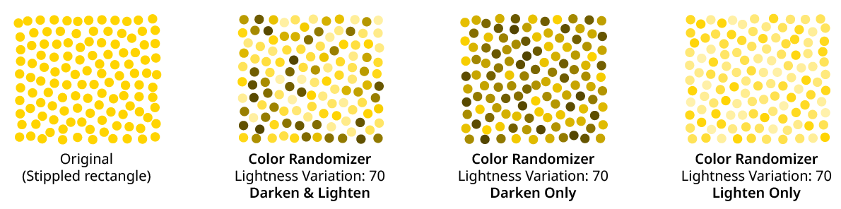
Color Randomizer Lightness Variation Examples
9. Apply at Grouping Level
Unless a live effect is applied above all strokes and fills (a “pre” effect), or inside a stroke or a fill and above other live effects, the art object internally passed to it is always a group. And this group may contain other groups, and so on. The Grouping Level controls the level at which the effect is applied, which affects what elements in the hierarchy get different random opacities. It can range from 0 (representing the top-level art) to 29 (the deepest level of group nesting allowed in Illustrator).
In the simplest case (when the effect is applied to a single stroked-and-filled path), the live effect mechanism separates the stroke from the fill, and passes a stroke-only path and a fill-only path to the live effect in a group. So while a Grouping Level of 0 would apply the same (random) hue change to the stroke and fill (because it is applied at the top grouping level), a Grouping Level of 1 would cause it to choose a different hue change for the fill than that of the stroke:
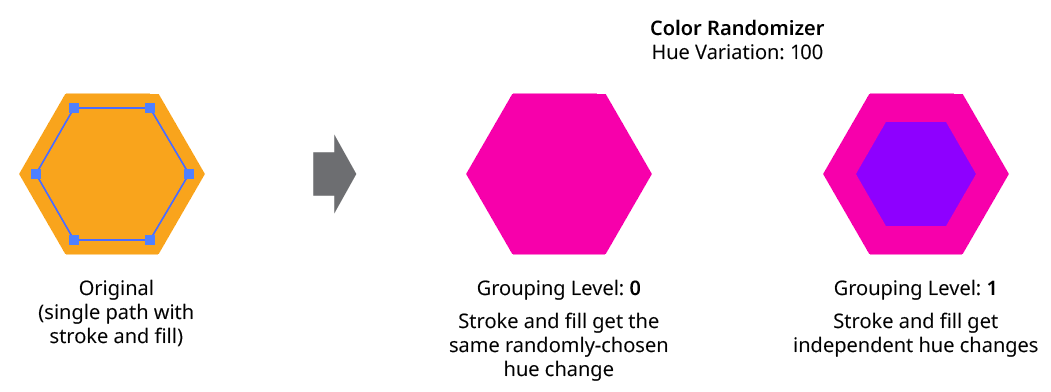
Color Randomizer Grouping Level on Simple Path
Next, consider the case of applying Color Randomizer to a group of stroked and filled paths. This top-level group may or may not have its own stroke and/or fill in its appearance. Here, the group passed to the effect has three groups inside it. One is composed of the paths with group level strokes (if there is no group level stroke, these would have no stroke or fill); another is composed of the paths with group level fills (similarly, if there is no group level fill, these would also have no stroke or fill); and the last is composed of the original paths in the group (and here, strokes and fills are not broken apart).
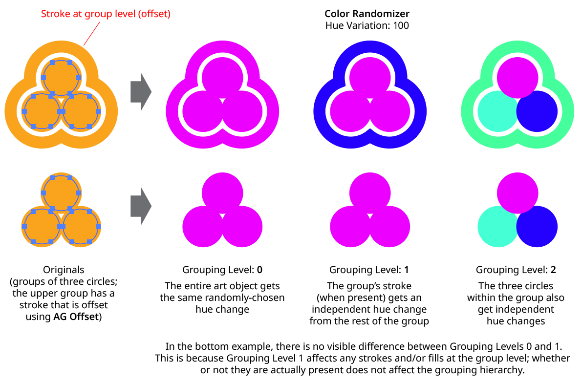
Color Randomizer Grouping Level on Group of Paths
In general, each nested group in the original art requires two Grouping Levels to “dig into,” due to the fact that a group stroke or fill can be present at each level. Because it can be difficult to anticipate what Grouping Level to use because the live effect mechanism can be complicated, it is recommended to simply increase the Grouping Level until the results are what is desired (changing the seed, if necessary, to see what is really changing independently). Setting the Grouping Level above the highest “valid” value will not cause a problem.
10. HSLuv
When enabled, the color changes are made using the HSLuv color space, which reduces perceived brightness changes when the hue and/or saturation is shifted.
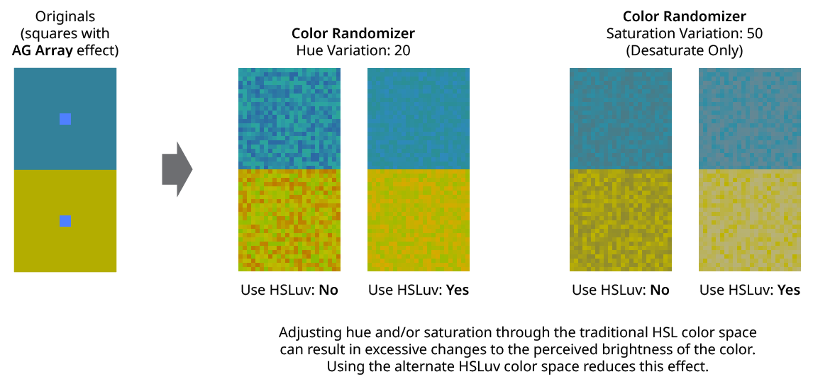
Color Randomizer Use HSLuv
11. Apply To Strokes/Fills
Allows strokes and/or fills to be ignored by the effect. If both options are turned off, the effect would still apply to raster images.
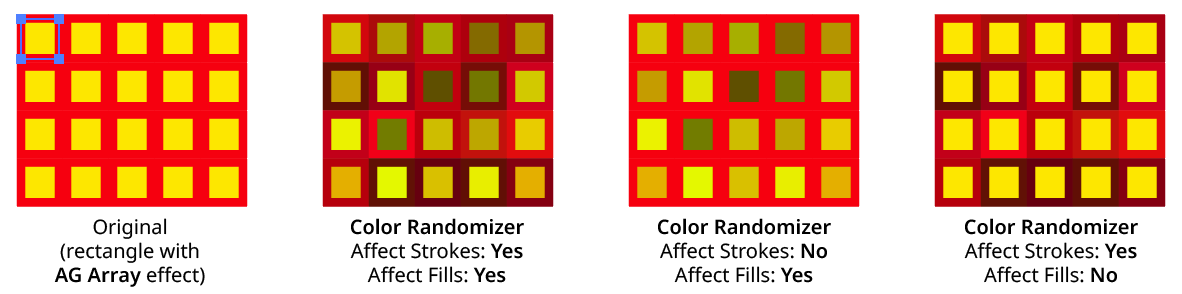
Color Randomizer Apply to Strokes/Fills
12. Filter Affected Art By Type
When enabled, only the art types that have a checkmark next to them will have their colors randomly changed. For example, if many images are each grouped with a text caption, the colors of just the images could be randomized by turning off the “Text” checkbox:

Color Randomizer Filter by Type Example
13. Filter Affected Art By Index
When enabled, each art object’s index is used to determine whether it should have its color randomly changed, using one of seven different methods. The index is simply an integer sequentially assigned to each object at the specified Grouping Level in the order it is encountered, starting with zero for the first object. Generally, the index increases going downwards in the stacking order; however, other live effects present in the appearance stack may change this order, sometimes randomly (such as PathFinder effects). The available By Index methods are as follows:
a. First: Only the first n objects are affected, where n is the specified value.

Color Randomizer by Index First Controls

Color Randomizer Filter by Index - First
b. Last: Only the last n objects are affected, where n is the specified value.

Color Randomizer by Index Last Controls

Color Randomizer Filter by Index - Last
c. First or Last: Only the first and last objects are affected.
d. Odd: Only objects with an odd index (1, 3, 5, 7...) are affected.
e. Even: Only objects with an even index (0, 2, 4, 6...) are affected.

Color Randomizer Filter by Index - Odd & Even
f. Pattern: Creates a repeating pattern of matching indices based on the three pattern parameters.

Color Randomizer by Index Pattern Controls
Initial Skip specifies the number of indices to skip over at the start (art with these indices will not be affected). Then, Match specified the number of indices that will match and therefore be affected. Finally, Skip specifies the number of indices to skip over following the matching indices. When the total of the values in the three parameters is less than the number of eligible art objects, the pattern repeats, using the Match and Skip values in alternation.
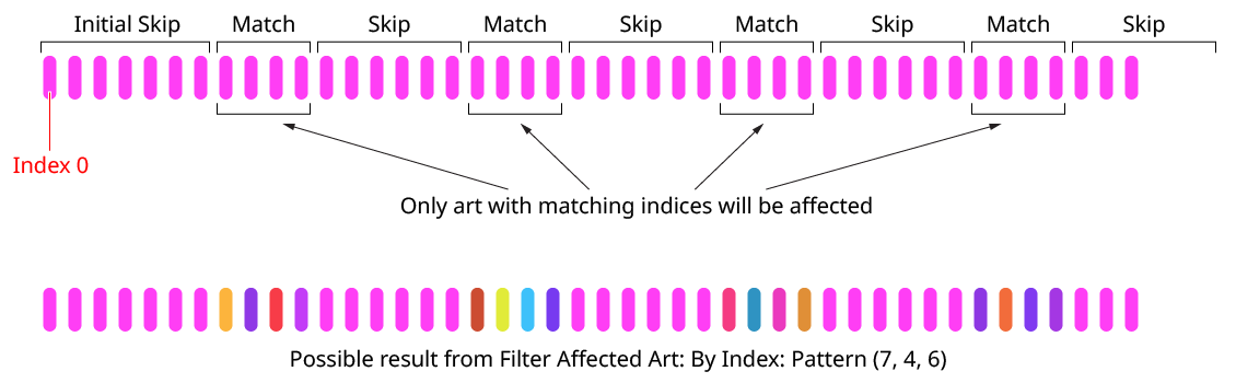
Color Randomizer Index by Pattern
g. Randomly: Each art object has the specified random chance (from 0% to 100%) of being affected. The parameter has a seed value that is independent from the hue/saturation/lightness seed values. Just as with those seed values, clicking the button picks a new seed, thereby changing the look of the artwork. To view or specify the seed number directly,
Option/Alt-clickthe button. This lets you recreate a previously-generated look.

Color Randomizer by Index Randomly Controls

14. Informational area
Shows a brief description of each control when the cursor is being hovered over it.
15. Preview
As with all live effects, when enabled, changing a parameter will immediately update the artwork while the dialog is still open.
16. Show Edges
By default, artwork selection edges are automatically hidden when the Color Randomizer parameters dialog is up, to make it easier to see color changes. However, by toggling the checkbox on, they may be shown again.
17. Defaults Popup Menu
Contains several functions concerning the default Color Randomizer settings. Default settings are those that initially appear in the parameters dialog whenever Color Randomizer is applied to art as a new effect (i.e., not when adjusting an existing instance of the effect).

Color Randomizer Defaults Menu
A. Save Current Settings as Defaults: The settings that are currently displayed in the dialog will be saved and used as the defaults in the future.
B. Restore Factory Defaults: The default settings will be restored to those that were in place when the plugin was installed and run for the first time. They will also automatically be loaded into the dialog.
C. Load Defaults: All current settings will be replaced with the default settings (which may have been customized through the first menu item).
18. Help Button
Opens the help documentation in the Astute Manager. If this does not automatically appear, please ensure your Astute Manager is running first.
Illustrator Location:
Illustrator Main Menu > Window > Astute Graphics > Phantasm > Halftone
A Euclidean dot shape was traditionally produced with analog halftoning methods. It starts out as a circle, but as the tint approaches 50%, it transitions into a square. Therefore, at 50% tint, the halftone pattern is a checkerboard. At higher tint levels, the dots invert, with the gaps between the dots forming circles. Such a dot shape is difficult to implement as vector art as areas of tints greater than 50% would essentially have to form one large compound path. However, Phantasm’s Pseudo-Euclidean dot shape can often be an acceptable approximation when the DPI is set to a fairly high value.
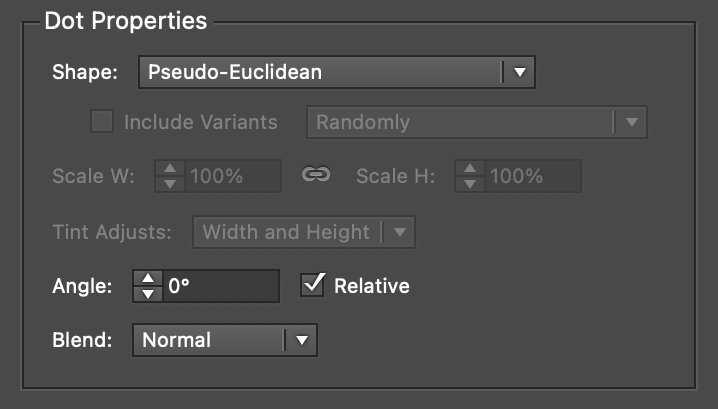
Phantasm Halftone Dot Properties - Pseudo-Euclidean
Because the Pseudo-Euclidean dots assume many different shapes which must touch to give the illusion of a continuous, inverted field for tints over 50%, dot scaling is not allowed, and the scaling controls are dimmed. While the dot angle may be changed from the default of 0%, it generally leads to undesirable results. Relative Angle should always be enabled, for the same reason. The Blend parameter acts identically to the Circle dot shape (see above).

Phantasm Halftone Pseudo-Euclidean Comparison Example
Pseudo-Euclidean dots generally do a better job representing the tonality of the original artwork, especially in shadow areas, without the need to adjust the Dot Gain curve:
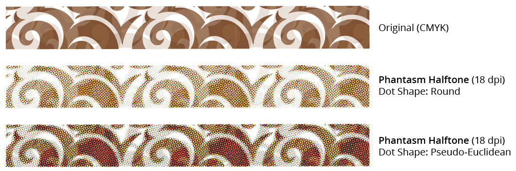
Phantasm Halftone Pseudo-Euclidean CMYK Comparison
Illustrator Location:
Illustrator Main Menu > Effect > Randomino > Opacity Randomizer...
Opacity Randomizer is an Astute Graphics live effect for randomly and non-destructively varying the opacity of one or more objects. Both linear and Gaussian random distributions are supported, and the applied opacity values can be rounded. Objects can be “filtered” so only some of them are affected, and, when applying the effect to nested groups, the depth at which it is applied can be specified.
Opacity Randomizer Example
As with most live effects, Opacity Randomizer appears in the main menu, under Effect > Randomino. It can also be applied directly from the Appearance panel using the “Add New Effect” button at the bottom of the panel.
Opacity Randomizer Parameters Dialog
After applying the live effect using the menu item (or when clicking on the existing effect in the Appearance panel to edit it), the parameters dialog will appear:
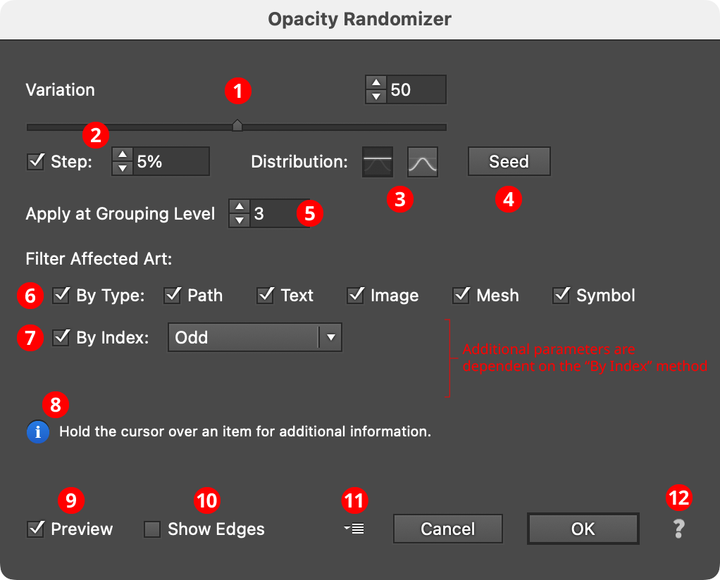
Opacity Randomizer Parameters Dialog
1. Variation
The amount of variation in opacity to apply, ranging from 0 (no variation) to 100 (maximum variation). The value can be changed with the slider or entered numerically in the text box. A variation of 20, for example, would apply opacities randomly ranging from 80% to 100%, while a variation of 75 would apply opacities from 25% to 100%.
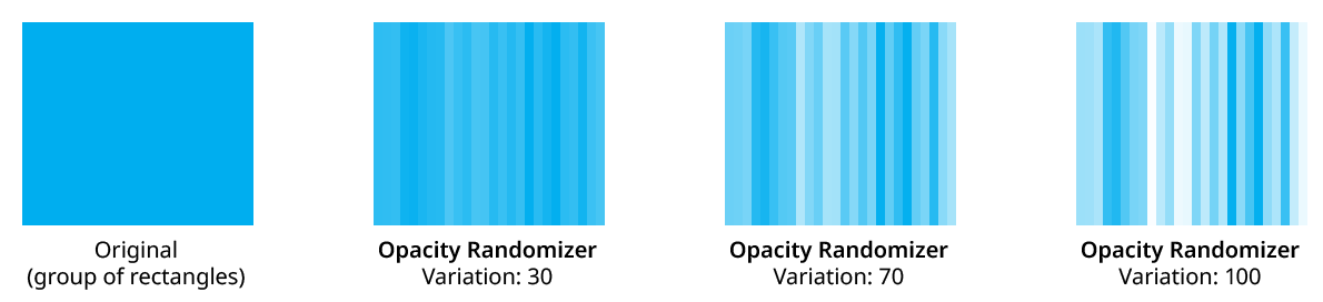
Opacity Randomizer Variation Examples
Because the opacities that Opacity Randomizer applies are multiplied onto existing opacities, final random opacities from 0% to 50%, say, may be achieved by setting the art’s overall opacity to 50% and then applying Opacity Randomizer with a variation of 100.
2. Step
Constrains each applied opacity value (after randomization) to multiples of the specified step value while still remaining in the original range (when possible). For example, if the variation is set to 34, then normally any opacity value between 66% and 100% might be produced — say, 87%. But enabling Step with a value of 10% would result in only values of 70%, 80%, 90%, or 100%.
3. Distribution Curves
Specifies either a linear distribution in random values (all values in the range are equally likely to be chosen) or a Gaussian distribution (central values in the range are more likely to be chosen).
4. Seed
Each random seed number leads to a different sequence of random values. Clicking the button picks a new seed, thereby changing the look of the artwork. To view or specify the seed number directly, Option/Alt-click the button. This lets you recreate a previously-generated look.
5. Apply at Grouping Level
Unless a live effect is applied above all strokes and fills (a “pre” effect), or inside a stroke or a fill and above other live effects, the art object internally passed to it is always a group. And this group may contain other groups, and so on. The Grouping Level controls the level at which the effect is applied, which affects what elements in the hierarchy get different random opacities. It can range from 0 (representing the top-level art) to 29 (the deepest level of group nesting allowed in Illustrator).
In the simplest case (when the effect is applied to a single stroked-and-filled path), the live effect mechanism separates the stroke from the fill, and passes a stroke-only path and a fill-only path to the live effect in a group. So while a Grouping Level of 0 would apply the same (random) opacity to the stroke and fill (because it is applied at the top grouping level), a Grouping Level of 1 would cause it to choose a different opacity for the fill than that of the stroke:
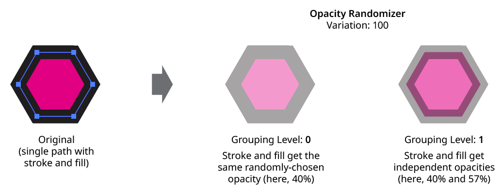
Opacity Randomizer Grouping Level on Simple Path
Next, consider the case of applying Opacity Randomizer to a group of stroked and filled paths. This top-level group may or may not have its own stroke and/or fill in its appearance. Here, the group passed to the effect has three groups inside it. One is composed of the paths with group level strokes (if there is no group level stroke, these would have no stroke or fill); another is composed of the paths with group level fills (similarly, if there is no group level fill, these would also have no stroke or fill); and the last is composed of the original paths in the group (and here, strokes and fills are not broken apart).
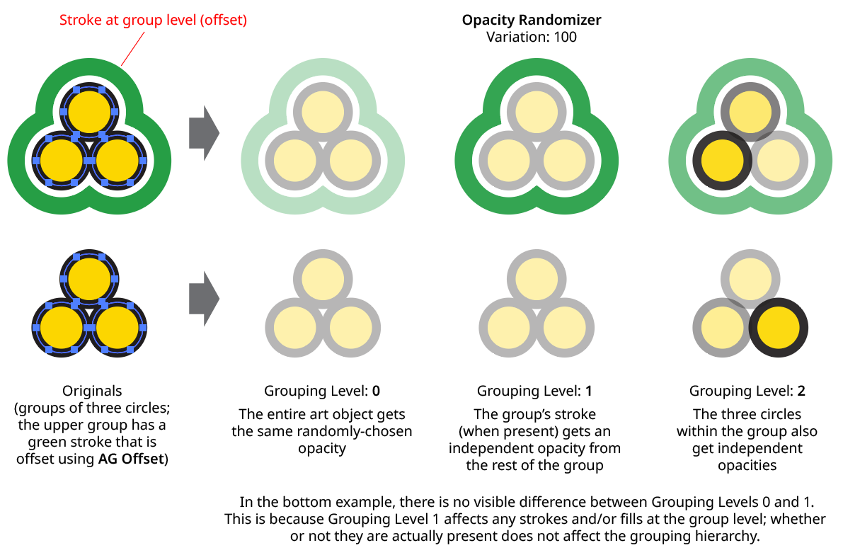
Opacity Randomizer Grouping Level on Group of Paths
In general, each nested group in the original art requires two Grouping Levels to “dig into,” due to the fact that a group stroke or fill can be present at each level. Because it can be difficult to anticipate what Grouping Level to use because the live effect mechanism can be complicated, it is recommended to simply increase the Grouping Level until the results are what is desired (changing the seed, if necessary, to see what is really changing independently). Setting the Grouping Level above the highest “valid” value will not cause a problem.
6. Filter Affected Art By Type
When enabled, only the art types that have a checkmark next to them will have their opacities randomly changed. For example, if many images are each grouped with a text caption, the opacities of just the images could be randomized by turning off the “Text” checkbox:

Opacity Randomizer Filter by Type Example
7. Filter Affected Art By Index
When enabled, each art object’s index is used to determine whether it should have its opacity randomly changed, using one of seven different methods. The index is simply an integer sequentially assigned to each object at the specified Grouping Level in the order it is encountered, starting with zero for the first object. Generally, the index increases going downwards in the stacking order; however, other live effects present in the appearance stack may change this order, sometimes randomly (such as PathFinder effects). The available By Index methods are as follows:
a. First: Only the first n objects are affected, where n is the specified value.

Opacity Randomizer by Index First Controls
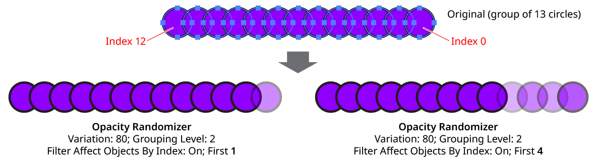
Opacity Randomizer Filter by Index - First
b. Last: Only the last n objects are affected, where n is the specified value.

Opacity Randomizer by Index Last Controls
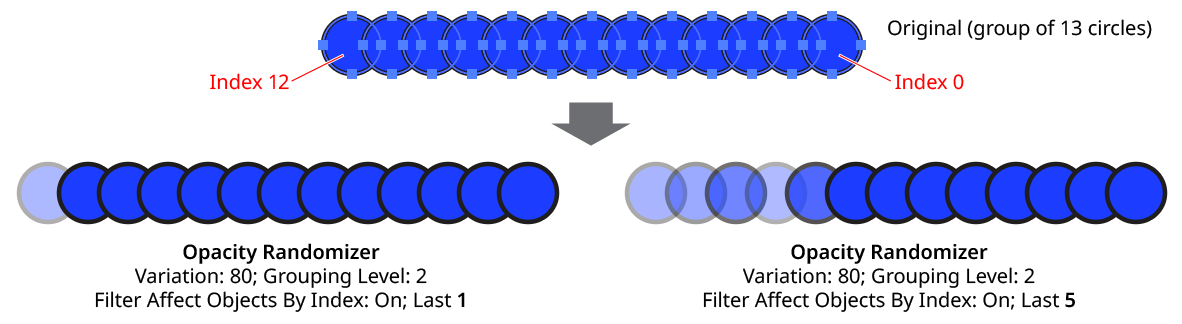
Opacity Randomizer Filter by Index - Last
c. First or Last: Only the first and last objects are affected.
d. Odd: Only objects with an odd index (1, 3, 5, 7...) are affected.
e. Even: Only objects with an even index (0, 2, 4, 6...) are affected.
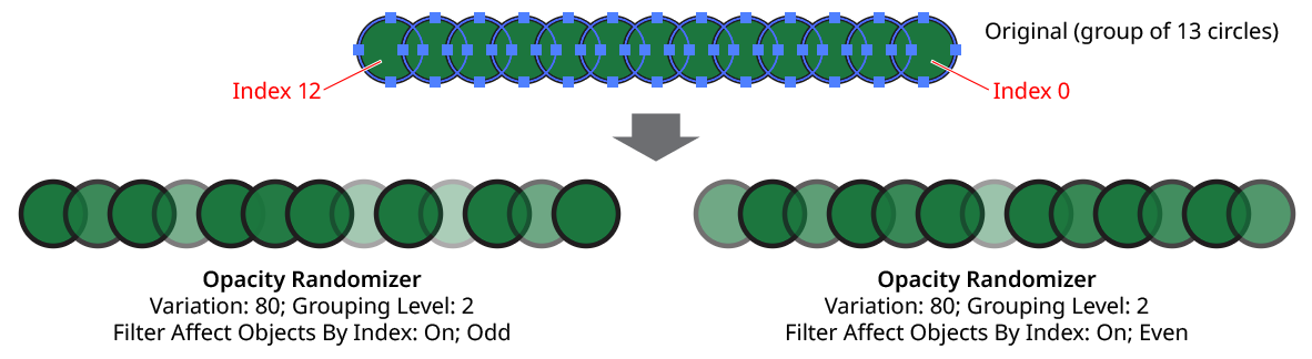
Opacity Randomizer Filter by Index - Odd & Even
f. Pattern: Creates a repeating pattern of matching indices based on the three pattern parameters.
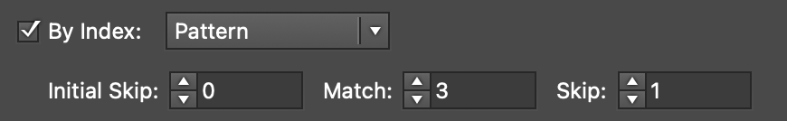
Opacity Randomizer by Index Pattern Controls
Initial Skip specifies the number of indices to skip over at the start (art with these indices will not be affected). Then, Match specified the number of indices that will match and therefore be affected. Finally, Skip specifies the number of indices to skip over following the matching indices. When the total of the values in the three parameters is less than the number of eligible art objects, the pattern repeats, using the Match and Skip values in alternation.
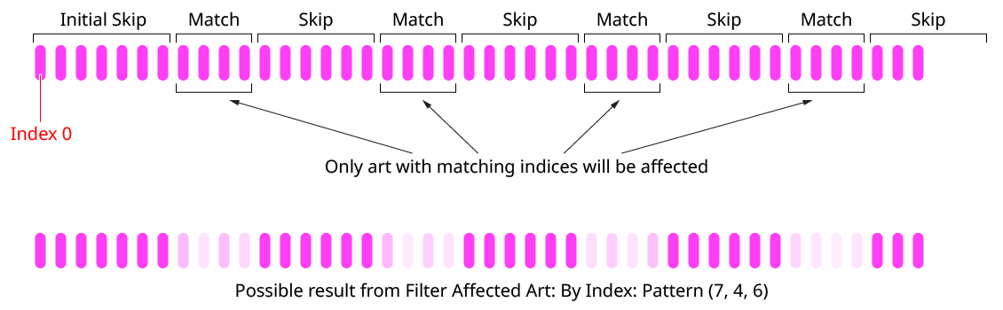
Opacity Randomizer Index by Pattern
g. Randomly: Each art object has the specified random chance (from 0% to 100%) of being affected. The parameter has a seed value that is independent from the main opacity seed value. Just as with that seed value, clicking the button picks a new seed, thereby changing the look of the artwork. To view or specify the seed number directly,
Option/Alt-clickthe button. This lets you recreate a previously-generated look.

Opacity Randomizer by Index Randomly Controls
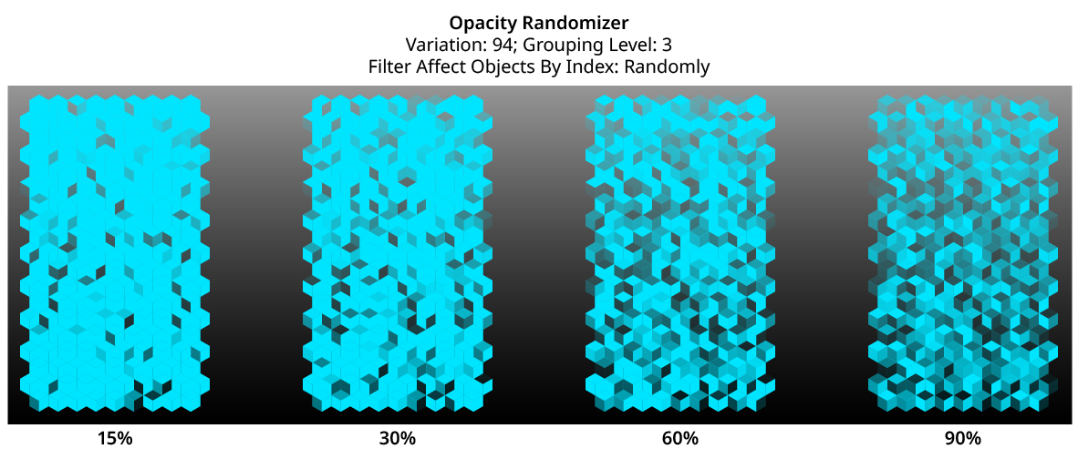
Opacity Randomizer Filter by Index - Randomly
8. Informational area
Shows a brief description of each control when the cursor is being hovered over it.
9. Preview
As with all live effects, when enabled, changing a parameter will immediately update the artwork while the dialog is still open.
10. Show Edges
By default, artwork selection edges are automatically hidden when the Opacity Randomizer parameters dialog is up, to make it easier to see opacity changes. However, by toggling the checkbox on, they may be shown again.
11. Defaults Popup Menu
Contains several functions concerning the default Opacity Randomizer settings. Default settings are those that initially appear in the parameters dialog whenever Opacity Randomizer is applied to art as a new effect (i.e., not when adjusting an existing instance of the effect).
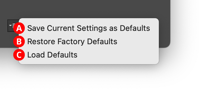
Opacity Randomizer Default Menu
A. Save Current Settings as Defaults: The settings that are currently displayed in the dialog will be saved and used as the defaults in the future.
B. Restore Factory Defaults: The default settings will be restored to those that were in place when the plugin was installed and run for the first time. They will also automatically be loaded into the dialog.
C. Load Defaults: All current settings will be replaced with the default settings (which may have been customized through the first menu item).
12. Help Button
Opens the help documentation in the Astute Manager. If this does not automatically appear, please ensure your Astute Manager is running first.
Illustrator Location:
The following operations can be recorded and played back as Actions:
1. User-Defined Favorite Buttons (recorded by position, not by content).
Illustrator Location:
Illustrator Main Menu > Window > Astute Graphics > Phantasm > Halftone
When the dot shape is set to Square or Line, the Dot Properties area is configured as follows:
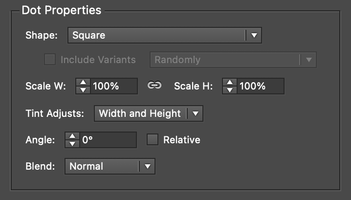
Phantasm Halftone Dot Properties - Square/Line
All of the parameters used for the Circle dot shape (with the exception of Roundness and Detail, which are not applicable) apply to Square and Line. The Line shape option constructs each “dot” out of a single, straight, stroked path. The line’s end caps are always set to rounded; if a different style end cap is required, there are two methods. The first is to add the additional Astute Graphics live effect Stroke Attributes, which can modify the end caps. The second method is to simply use a Square shape type instead, and change the Scale W parameter to be smaller than the Scale H.
Illustrator Location:
Illustrator Main Menu > Window > Astute Graphics > AG Architect
AG Architect is an Astute Graphics live effect that adds extension lines to path segments, which can be used to give live text or paths an architectural blueprint feel, or for other special effects. A wide variety of parameters can be specified through a panel interface, such as whether the lines appear on curved or straight segments; the lines’ length, style, and position; and whether or not to randomize the results. AG Architect is part of the Stylism plugin.
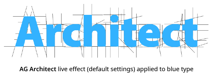
AG Architect Default Example
As with most live effects, AG Architect appears in the main menu, under Effect > Stylism > AG Architect. It can also be applied directly from the Appearance panel using the “Add New Effect” button at the bottom of the panel. However, the easiest way to apply the live effect is using the Apply button on the AG Architect panel.
Illustrator Location:
Illustrator Main Menu > Window > Astute Graphics > Phantasm > Halftone
The Character dot shape allows the use of text characters as halftone dots. When the dot shape is set to Character, the Dot Properties area is configured as follows:
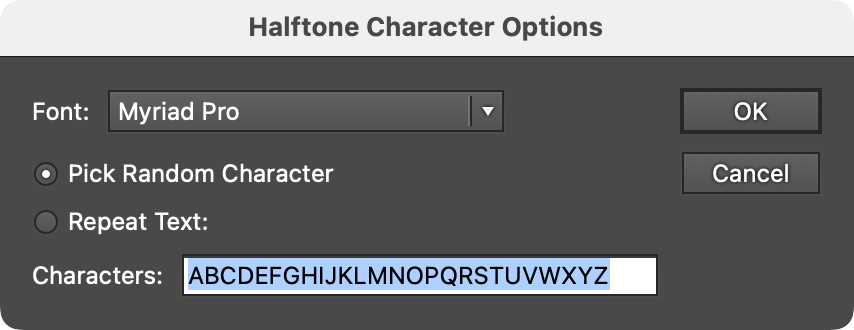
Phantasm Halftone Character Options Dialog
A. Options
Opens the Halftone Character Options dialog:
Phantasm Halftone Character Options Dialog
The font of the characters may be chosen using the pull-down menu. Generally, heavier typefaces give closer color-matching results as glyphs in the lighter ones do not offer sufficient area. If Pick Random Character is enabled, each dot will use a random character from the characters which appear in the Characters field (by default, the English uppercase alphabet; up to 2047 characters may be entered). Characters may be entered more than once to increase their random frequency. When Repeat Text is enabled, dots will use the characters in their entered order, repeating as necessary.
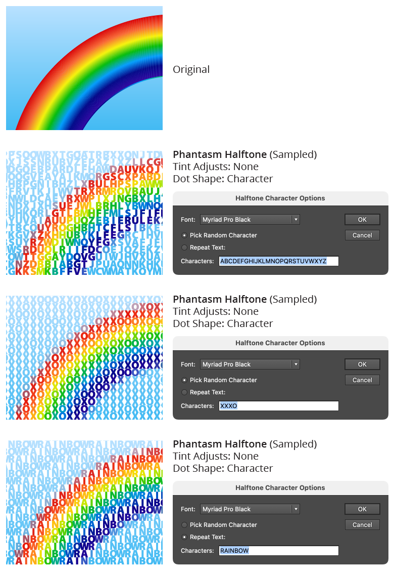
Phantasm Halftone Character Examples
All of the parameters used for the Circle dot shape (with the exception of Roundness and Detail, which are not applicable) apply to Character.
Illustrator Location:
Illustrator Main Menu > Window > Astute Graphics > AG Architect
The AG Architect live effect does not have a modal parameters dialog, but is instead edited using a panel, which can be shown and hidden using the menu item found in the main menu at Window > Astute Graphics > AG Architect. When at least one selected object has the AG Architect live effect applied, the panel controls will update to reflect the parameters of those effects, which can then be edited. A value field which is blank or (for checkboxes) with a dash indicates that the parameter has different values in the selection. These can be unified (made the same) by entering a new value.
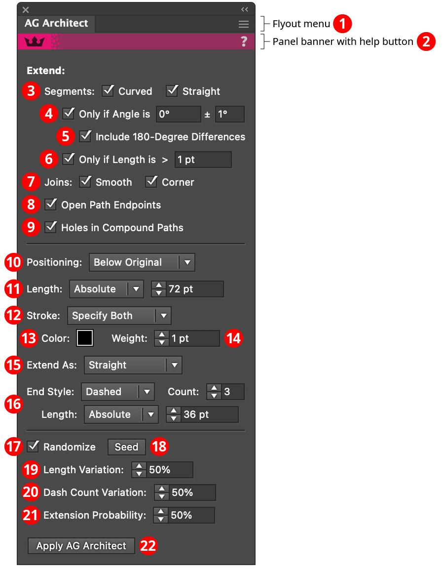
AG Architect Panel
1. Flyout menu
See AG Architect Panel: Flyout Menu.
2. Panel banner
The help button on the right opens the help documentation in the Astute Manager. If this does not automatically appear, please ensure your Astute Manager is running first.
3. Segments
Extension lines will be added to path segments which are curved and/or straight, when the corresponding option is enabled.
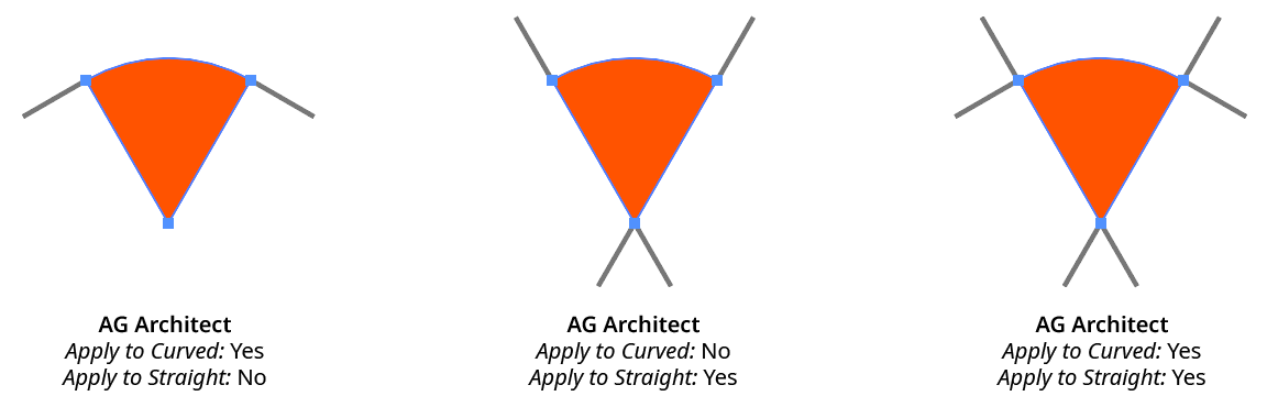
AG Architect Curved Straight Example
4. Only If Angle Is
When enabled, extension lines are only added if their angle matches the specified value (within the specified tolerance). Angles are measured using the normal Illustrator convention.
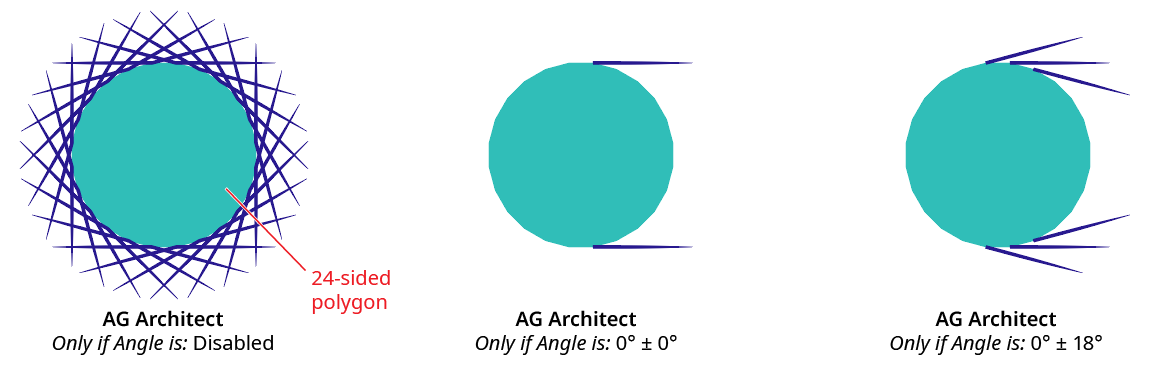
AG Architect Only if Angle is Example
5. Include 180-Degree Differences
When using the Only if Angle is setting, specifies that directions 180° from the specified angle should be considered the same.

AG Architect 180 Degree Difference Example
6. Only If Length is
When enabled, extension lines are only added to path segments that are longer than the specified length.
7. Joins
Extension lines will be applied at the ends of path segments which end in smooth or corner anchor points, when the corresponding option is enabled.
8. Open Path Endpoints
Extension lines will be added at the ends of open paths.
9. Holes in Compound Paths
Extension lines will be applied to path segments which comprise subpaths which form holes in compound paths.
10. Positioning
The stacking position of the extension lines relative to the original source art, from among Above Original, Replace Original, or Below Original.
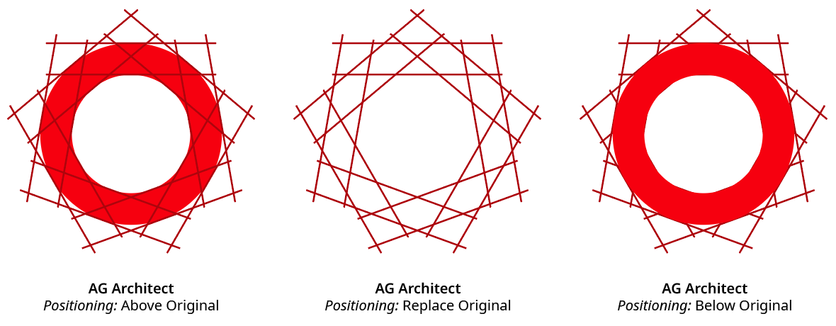
AG Architect Positioning Example
11. Length
The base length of the extension lines (before any randomization). When the dropdown menu is set to Absolute, the length is specified as an absolute value (for example, 15 pt). When the dropdown men is set to Relative, the length is specified as a percentage of the diagonal length of the source path’s bounding box.
12. Stroke
The stroke style of the extension lines, as specified using the dropdown menu. When set to Use Original, the stroke’s style is taken from the original source path (except dashes are not preserved). Otherwise, the color, weight, or both is set to the specified values.
13. Color
Available when the stroke is set to Specify Color or Specify Both; specifies the color of the extension lines. Clicking the color chip brings up a standard color picker dialog.
14. Weight
Available when the stroke is set to Specify Weight or Specify Both; specifies the stroke weight of the extension lines.
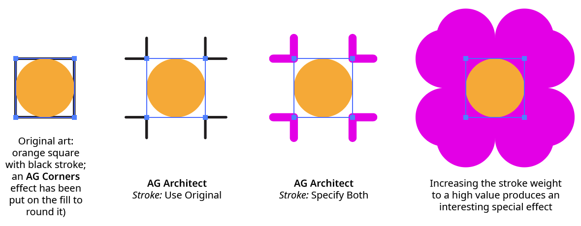
AG Architect Stroke Example
15. Extend As
Specifies the extension’s geometry, either Straight (all extension lines are straight) or Smooth Curve (extensions from curved path segments will also be curved, following the natural extension of the bezier curve’s shape).
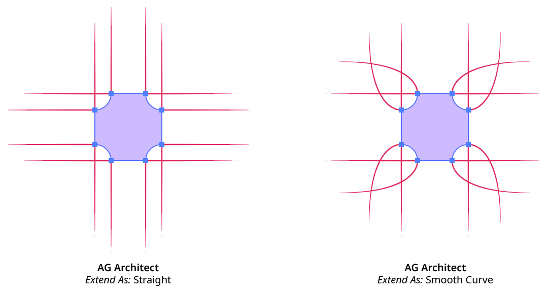
AG Architect Extend As Example
16. End Style
Specifies the style for the terminus of the extension lines.
Normal extension line end without any special treatment; the end cap type is either taken from the stroke on the original path (if the Stroke setting is set to Use Original or Specify Color), else is set to Butt Cap type.
Tapered extension line thin to a sharp point. The length of the tapered portion of the line can be specified either as an absolute distance or as a percentage of the total line length. When AG Architect effects with Tapered extension lines are expanded, the lines are converted into closed path shapes.
Dashed extension line end in one or more dashes, which shorten towards the end of the line. The number of dashes can be changed (from 1 to 9), and the length of the dashed portion of the line can be specified either as an absolute distance or as a percentage of the total line length.
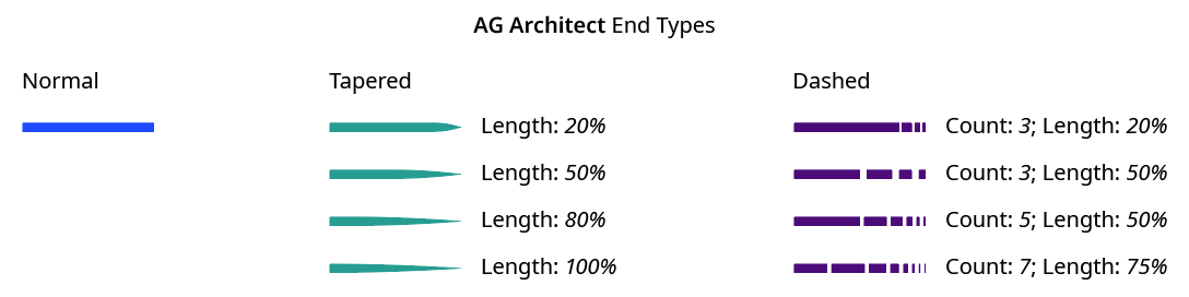
AG Architect End Styles
17. Randomize
When enabled, several of the live effect’s parameters can be randomly varied: the length of the extensions, the dash count (if Dashed end type is used), and the probability that an extension line will be created at all.
18. Seed
Each random seed number leads to a different sequence of random values. Clicking the button picks a new seed, thereby changing the look of the artwork. To view or specify the seed number directly, Option/Alt-click the button. This lets you recreate a previously-generated look.
19. Length Variation
When randomization is enabled, specifies the maximum amount of variation in the final extension line length. For example, if the length is set to 20 pt, then a variation value of 25% would produce lengths that vary by as much as 20 pt × 25% = 5 pt, that is, between 15 pt and 20 pt; a variation value of 90% would produce lengths between 2 pt and 20 pt.
20. Dash Count Variation
When randomization is enabled, specifies the random variation in the dash count (when using the Dashed end type). For example, if the count is set to 8, then a variation value of 25% would produce count values that vary by as much as 8 × 25% = 2, that is, either 7 or 8; a variation value of 100% would produce count values between 1 and 8.
21. Retention Probability
When randomization is enabled, specifies the probability that an extension line will be created at each spot where one is eligible.
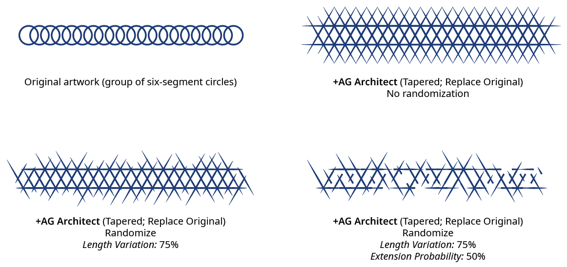
AG Architect Randomization
22. Apply Button
Click to apply the AG Architect live effect to the selected artwork, with the parameters set as they currently exist in the panel. If the button is not available, then either nothing is selected or the selection already contains at least one object with an AG Architect effect. If the button is clicked with Shift pressed, the extension lines will be added and immediately detached, essentially creating them as editable artwork rather than as a live effect. However, this loses the ability to preview the effect first.
Illustrator Location:
Illustrator Main Menu > Window > Astute Graphics > Phantasm > Halftone
Available when there is at least one symbol in the document, the Symbol dot shape allows symbols to be used as halftone dots. Each symbol that is not a variant (see below) appears in the pull-down menu, in alphabetical order, and can be chosen as the shape to use for the dots. The Dot Properties area is configured as follows:
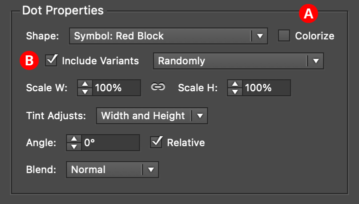
Phantasm Halftone Dot Properties - Symbol
A. Colorize
By default, symbols remain in their original colors. However, by enabling Colorize, each symbol will have all of its fills and strokes changed to the color that the dot would normally have if it were of Circle shape, say.
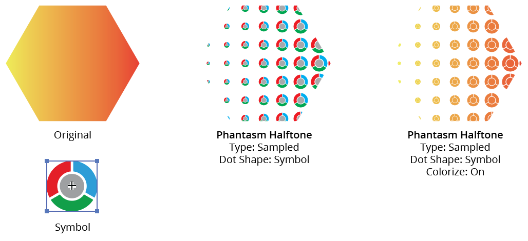
Phantasm Halftone Symbol Colorize
B. Include Variants
If the chosen symbol from the Shape pull-down menu has “variants,” this setting (disabled by default) allows them to be used in addition to the base symbol. The variants must have been created before applying the Phantasm Halftone effect to the artwork. For more information on symbol variants, see Phantasm Halftone: Symbol Variants. Additionally, when a symbol is chosen as the dot shape, a Tips button will appear on the dialog; when clicked, it brings up a dialog summarizing symbol variant creation and naming.
All of the parameters used for the Circle dot shape (with the exception of Roundness and Detail, which are not applicable) apply to Symbol.
Illustrator Location:
Illustrator Main Menu > Window > Astute Graphics > AG Architect > Panel Flyout Menu
The AG Architect panel flyout menu items are contextually sensitive and all items may not be available, depending on the current selection.
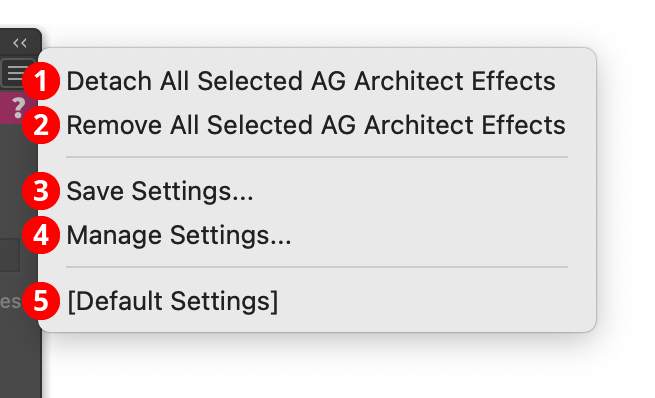
AG Architect Panel Flyout Menu
1. Detach All Selected AG Architect Effects
Changes the extension lines created by all AG Architect live effects in the selection into editable artwork, and removes the effect from the appearance(s). This is similar to using the native menu command Object > Expand Appearance, but is more flexible because it leaves the existing artwork (and other live effects which may be present) intact.
2. Remove All Selected AG Architect Effects
Removes any AG Architect live effects from the selection. (This can be done from the Appearance panel as well, but not if multiple AG Architect effects are present with different parameters. In that case, the Appearance panel will simply display “Mixed Appearances” and the ability to select the live effect and delete it will no longer be available.)
3. Save Settings...
Captures all of the current parameter settings on the panel to a file, which can be instantly recalled later (either in the current file session or a later one). A dialog will appear through which the file name may be specified.
4. Manage Settings...
Brings up a dialog through which existing settings files may be renamed or deleted:

AG Architect Manage Settings Dialog
A. Settings List: Shows all user-saved settings. One or more settings files can be selected for use with the buttons at the bottom of the dialog by clicking on them in the list, with Shift pressed to select contiguously or Command/Ctrl pressed to select discontiguously, as normal.
B. Rename Button: If a single settings file is selected, allows it to be renamed, through a separate dialog. If the Cancel button is used, the original names will be restored.
C. Delete Button: Removes the selected settings file(s). The files are not permanently deleted until the OK button is clicked.
5. Settings Files
User-defined settings will appear below the built-in [Default Settings] menu item. Choosing a settings menu item will load the panel with the settings it had when the file was saved; the AG Architect effects in any selected art will be updated to match.
Illustrator Location:
Illustrator Main Menu > Window > Astute Graphics > Phantasm > Halftone
Halftone can use more than one symbol within a single applied effect by utilizing symbol variants, which are simply additional symbols with special names that enable Halftone to identify them as belonging to one “group”. An advanced naming technique allows further control over the distribution of each variant within the halftone.
There are two ways to create symbol variants: automated and manual.
Halftone Symbol Variants: Automated creation
Note: The automated creation method requires the Astute Graphics Stipplism plugin to be installed.
1. Create the base symbol first. Due to internal limitations, automatically-created variants are always created as Static Type symbols, so it is best to also use the Static Type symbol when creating the base symbol, because otherwise they may react differently to scaling when the general preference Scale Strokes & Effects is disabled.
2. Create other artwork which will be used as the variants. These may be similar to the base symbol (such as just having a different color), but they may also be completely different. If a variant is composed of more than one object, the objects need to be grouped.
3. With the artwork selected, choose Object > Create Symbol Variants... from the main menu to display the Create Symbol Variants dialog.
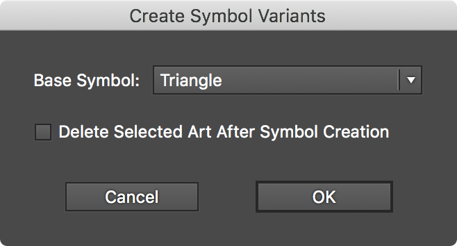
Phantasm Halftone Symbol Variants Dialog
4. Pick a symbol to use as the base symbol from the pull-down menu.
5. Enable Delete Selected Art After Symbol Creation if you don’t want the original objects to be retained on the artboard. Note that the retained artwork won’t be replaced with their respective newly-created symbols they way Illustrator does when a symbol is created manually.
6. Click OK to finish.
To see the result, open the native Symbols panel. If the symbol names are not visible, from its flyout menu choose either the Small List View or Large List View menu item.
The chosen objects are added as symbols, but with special names assigned. For example, given a base symbol name of Triangle, its symbol variants would have names like these:
Triangle_var_001
Triangle_var_002
Triangle_var_003
Halftone Symbol Variants: Manual creation
The special _var_[string] suffix, added to the base name, is the sole determinant of whether a symbol is considered a variant or not. Therefore, symbols can be named manually using this pattern to turn them into variants. The Tab key can be used to quickly rename symbols in succession. While the automated method of variant creation uses a three-digit number that increments as the string following the _var_ suffix, it need not be a number; it can be any unique identifying name. So the following names would also be equally valid:
Triangle_var_darker
Triangle_var_verydark
Triangle_var_black
Halftone Symbol Variants: Usage
To use symbol variants in addition to the base symbol in Halftone, simply enable the Use Variants checkbox in the parameters dialog. Note that only base symbols will appear in the list of available symbols, so variants can’t be used independently. For each halftone symbol dot, either the base symbol or one of its variants are chosen at random with equal frequency, unless additional naming options have been used to specify the density distribution (see below).
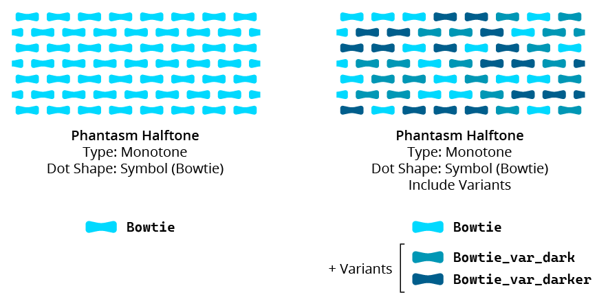
Phantasm Halftone Symbol Variants Example
Halftone Symbol Variants: Density Specification
Additional naming syntax allows control over the distribution of symbol variants used within a Halftone. The following suffix can be added to a variant symbol’s name to make it a density-specified variant (its position in the halftone is restricted to a density range):
=dxxx-xxx (where each xxx is a three-digit number between 000 and 255) means the variant will be only used within the halftone where the underlying grayscale-equivalent tone (as measured from 0–255) is equal to or between the two specified values. The smaller value must come first in the name. If the underlying tone lies inside more than one variant’s density range specifier, then the variant is randomly picked from among the valid variants, thereby creating a mix of symbols in certain areas.
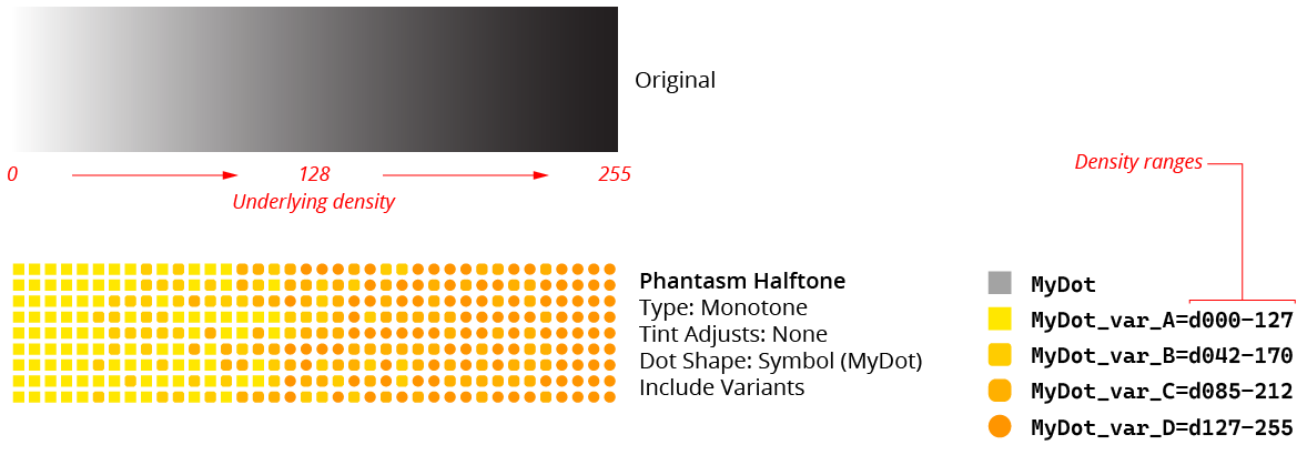
Phantasm Halftone Symbol Variants - Density Specified
If any density-specified variants are present, then the base symbol and any normal variants will not be used at all. If a variant name is changed after the Halftone is created, the live effect will not be updated until its parameters dialog is opened.
Illustrator Location:
Illustrator Main Menu > Window > Astute Graphics > Phantasm > Hue/Saturation
Phantasm Hue/Saturation is a live effect/filter that allows hue, saturation, and lightness correction of artwork similar to Photoshop’s. As a live effect, it is accessible through the main menu, under Effect > Phantasm > Hue/Saturation. It can also be applied directly from the Appearance panel using the “Add New Effect” button at the bottom of the panel, or through the Phantasm panel (see Phantasm: Panel).
After applying the live effect using the menu item (or when clicking on the existing effect in the Appearance panel to edit it), the parameters dialog will appear:
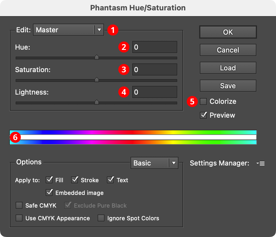
Phantasm Hue/Saturation Dialog
1. Hue Range Pull-down Menu
When set to Master, the adjustments will apply to all colors in the artwork. However, it can also be changed to one of six independent hue ranges. By default, these are: Reds, Yellows, Greens, Cyans, Blues, and Magentas. Each color can have its own adjustment parameters, with variable start, fade-in, end, and fade-out parameters (see item 6 below). These color ranges refer the artwork’s original colors, not the color that results from any Master adjustment. The menu is not available when Colorize is being used.
2. Hue
Adjusts the hue of the art, from –180 to 180. The slider may be dragged, or a numerical value entered directly.
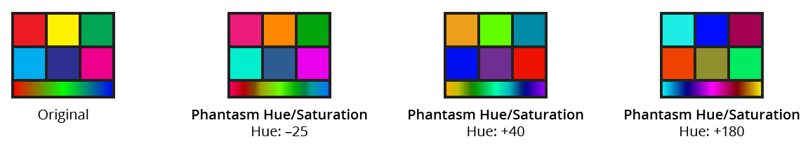
Phantasm Hue Examples
3. Saturation
Adjusts the saturation of the art, from –100 to 100. The slider may be dragged, or a numerical value entered directly.
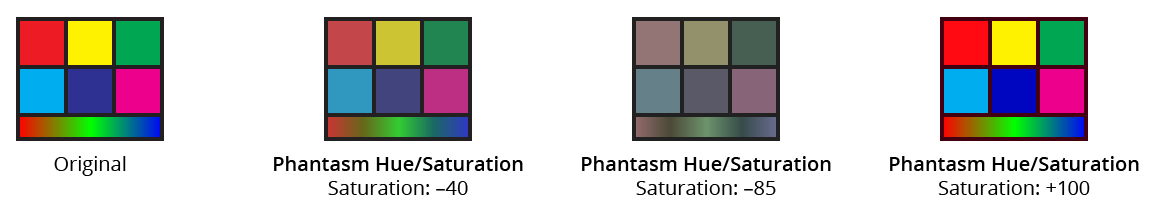
Phantasm Saturation Examples
4. Lightness
Adjusts the lightness of the art, from –100 to 100. The slider may be dragged, or a numerical value entered directly.
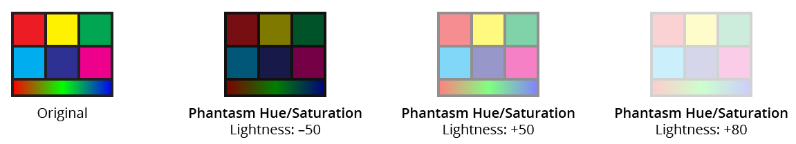
Phantasm Lightness Examples
5. Colorize Checkbox
When enabled, the hue/saturation/lightness functionality is changed; the artwork is changed to a single hue, with adjustable saturation and lightness. In Colorize mode, the Hue parameter changes to a range of 0 to 360, and the Lightness parameter changes to a range of 0 to 100. The Hue Range Pull-down Menu is no longer available.
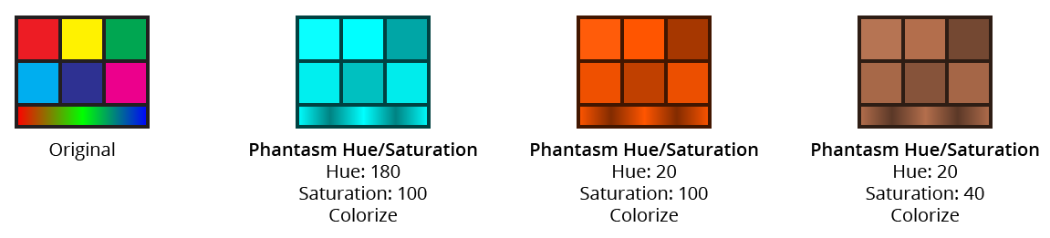
Phantasm HLS with Colorize Examples
6. Color Range Stripes
The top stripe represents the original colors, and the bottom stripe shows the corresponding colors after adjustment. Certain adjustments may not be clearly reflected in the stripes, such as increasing the saturation, as the colors shown are already saturated. When adjusting a hue range other than Master, the stripes will also display controls which offer the ability to adjust the start, fade-in, end, and fade-out parameters for that range:
Phantasm HLS with Colorize Examples
To edit the hue range controls, drag the inner controls (B and D) to specify the range that will be affected 100% and the outer controls (A and E) for the fade-in/fade-out limits. Dragging the area marked C will move all four controls together. It is also possible to drag the regions between controls A and B, and between D and E, to move the pair of controls together (this also makes it possible to put A or E on the opposite end of the stripe from its corresponding inner control). Numeric values are shown for each control’s position above the upper color stripe (a, b, d, and e).
The Hue Range menu color name entries will adjust automatically to best describe the range that is described by the controls. If there are multiple ranges that describe the same basic color, a number will be appended to the color name (for example, there might be Reds and Reds 2).
Illustrator Location:
Illustrator Main Menu > Window > Astute Graphics > Phantasm > Invert
Phantasm Invert is a live effect/filter that simply inverts the levels of all color channels. As a live effect, it is accessible through the main menu, under Effect > Phantasm > Invert. It can also be applied directly from the Appearance panel using the “Add New Effect” button at the bottom of the panel, or through the Phantasm panel (see Phantasm: Panel).
After applying the live effect using the menu item (or when clicking on the existing effect in the Appearance panel to edit it), the parameters dialog will appear:
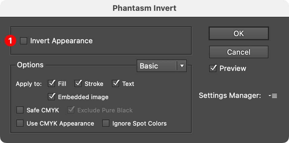
Phantasm Invert Dialog
1. Invert Appearance
Available only if the document is in CMYK color space. Most common CMYK colors do not have large amounts of Black in them, so when that channel is inverted, the Black level becomes high and the colors typically get very dark. When Invert Appearance is enabled, artwork is instead inverted in a visually-similar way to how RGB artwork would be inverted, which is generally more useful:
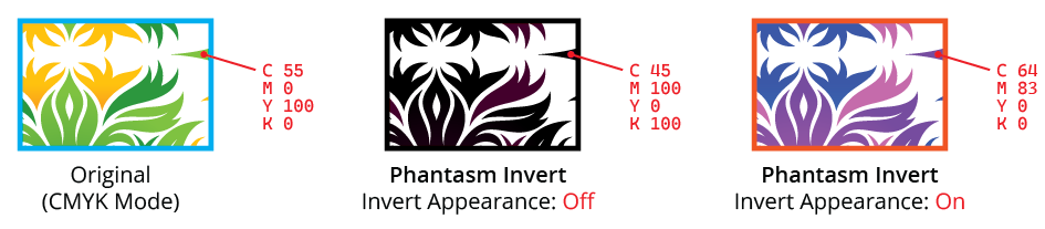
Phantasm Invert Example
Illustrator Location:
Illustrator Main Menu > Window > Astute Graphics > Phantasm > Levels
Phantasm Levels is a live effect/filter that allows adjustment of the black, white, and mid-point gray input levels and output levels of artwork, similar to Photoshop’s Levels dialog. As a live effect, it is accessible through the main menu, under Effect > Phantasm > Levels. It can also be applied directly from the Appearance panel using the “Add New Effect” button at the bottom of the panel, or through the Phantasm panel (see Phantasm: Panel).
After applying the live effect using the menu item (or when clicking on the existing effect in the Appearance panel to edit it), the parameters dialog will appear:
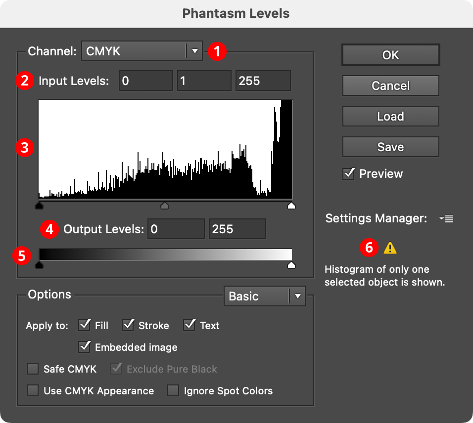
Phantasm Levels Dialog
1. Channel Menu
Specifies which channel or channels the current levels settings apply to. For CMYK documents, this includes the composite four process colors (CMYK) as well as each individual color. For RGB documents, this includes the composite three primary colors (RGB) as well as each individual color. In both cases, individual spot colors will also appear in the list, as well as Image Alpha, which affects the alpha channel in images with transparency.
2. Input Levels
Sets the levels for the shadows (0 to 253), midtones (0.1 to 9.99), and highlights (2 to 255). The shadow and highlight levels are absolute values, while the midtone value is always relative to them.
3. Histogram
Shows the levels of the tints of the selected channels within the targeted art as a histogram. Due to plugin limitations, if the Levels live effect is applied to multiple targeted art objects, a histogram of only one of them can be displayed (a warning will be shown). Histograms that cannot be displayed, such as for Image Alpha, will show a “Null” symbol (a circle with a slash through it). The slider thumbs under the histogram reflect the current input levels, and can also be dragged to adjust them.
4. Output Levels
Sets the tonal range that the adjusted art will assume. The shadow level can be brought to the right of the highlight level, in which case the levels will be inverted.
5. Output Level Slider
The slider thumbs reflect the current output levels, and can be dragged to adjust them.
6. Warning Area
Displays warnings, such as when the effect is being applied to multiple targeted art objects, or when a spot color is present in the artwork.
Illustrator Location:
Advanced Toolbar > Stylism Stack > AG Block Shadow
The AG Block Shadow tool appears in Illustrator’s main toolbar (which must be in Advanced mode: View > Toolbars > Advanced), stacked under the Stylism tool. As with other stacked tools, click and hold on the top tool icon to display the tools stacked under it.
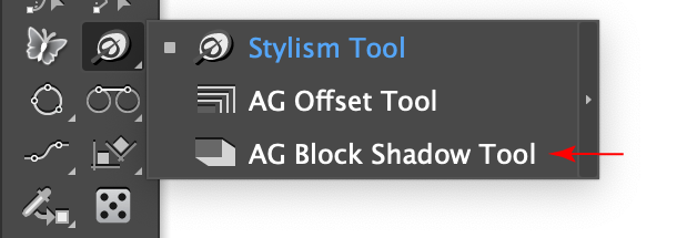
AG Block Shadow Tool Location
The AG Block Shadow tool’s cursor is a crosshair, except when previewing a new shadow or adjusting an existing shadow, in which case it appears as an arrowhead with a shadow:
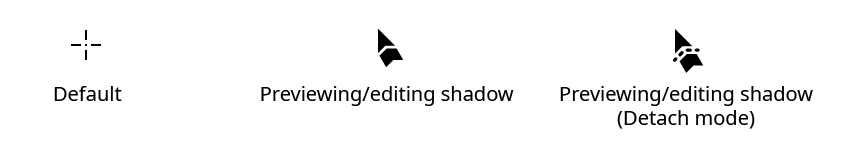
AG Block Shadow Tool Cursors
Illustrator Location:
Illustrator Main Menu > Window > Astute Graphics > Phantasm > Prepress Correct
Phantasm Prepress Correct is a live effect/filter for CMYK documents destined for print that offers the most common ink control operations from the Basic and Advanced Options section present in most of Phantasm’s other live effects.
As a live effect, it is accessible through the main menu, under Effect > Phantasm > Prepress Correct. It can also be applied directly from the Appearance panel using the “Add New Effect” button at the bottom of the panel, or through the Phantasm panel (see Phantasm: Panel).
After applying the live effect using the menu item (or when clicking on the existing effect in the Appearance panel to edit it), the parameters dialog will appear:
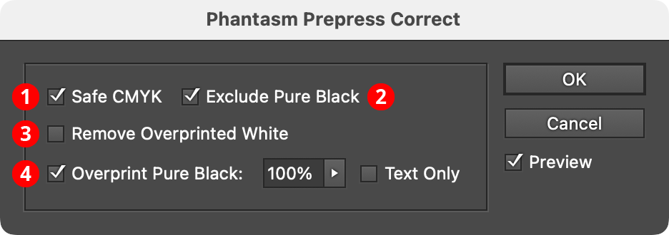
Phantasm Prepress Correct Dialog
1. Safe CMYK
When enabled, if the document’s color mode is set to CMYK, colors will have their ink levels adjusted to conform to the color setting in regards to total ink coverage. For example, typically offset presses require that the total ink in any one spot on the paper is 300% total coverage or less. See Phantasm: Common Options (Basic).
2. Exclude Pure Black
Available if Safe CMYK is enabled. This option keeps any Safe CMYK adjustment, which usually has the effect of adding C, M, and Y components, from being applied to pure black colors.
3. Remove Overprinted White
Removes the overprint flag from any white art objects, which normally would cause them to disappear completely on separated output for printing.
4. Overprint Pure Black
Adds the overprint flag to art objects which are pure black, which can be beneficial by reducing knockout/alignment issues that can occur on an offset press. The associated slider determines the percentage of Black, and above, that should have the overprint flag added. For example, if the slider is set to 75%, only objects colored with 75% Black (no Cyan, Magenta or Yellow) or 75% grayscale or above would have an overprint setting added (if not already present). The overprint would only apply to the relevant fill or stroke, or both. Enabling the associated Text Only checkbox will limit the flag to pure black editable text objects. Gradient meshes and bitmaps are not affected by Overprint Pure Black.
Illustrator Location:
Advanced Toolbar > Stylism Stack > AG Block Shadow
As the AG Block Shadow tool has several keypresses for certain operations, we suggest installing the free Astute Graphics plugin Astute Buddy, which creates a panel that dynamically updates to inform you of the various keys which can be pressed in the tool’s current context.
The AG Block Shadow tool is works in conjunction with the associated AG Block Shadow panel, which generally should be open and accessible. If you are using the free Astute Graphics plugin DirectPrefs, you can have the AG Block Shadow panel automatically be shown when the AG Block Shadow tool is selected.
The AG Block Shadow tool offers a graphical method for both adding and editing AG Block Shadow live effects.
Illustrator Location:
Illustrator Main Menu > Window > Astute Graphics > Phantasm > Shift to Color
Phantasm Shift to Color is a live effect/filter that allows moving all of an art object’s colors towards a specified color by a variable amount, simulating transparency without actually using it. This may be useful when exporting to basic vector formats or other situations where using actual transparency might require flattening which can cause other issues.
As a live effect, it is accessible through the main menu, under Effect > Phantasm > Shift to Color. It can also be applied directly from the Appearance panel using the “Add New Effect” button at the bottom of the panel, or through the Phantasm panel (see Phantasm: Panel).
After applying the live effect using the menu item (or when clicking on the existing effect in the Appearance panel to edit it), the parameters dialog will appear:
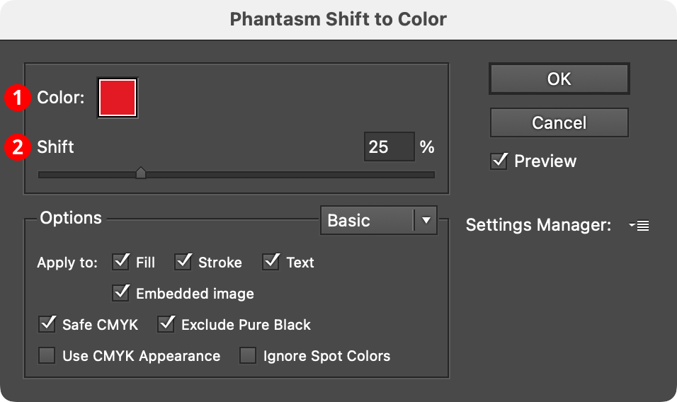
Phantasm Shift to Color Dialog
1. Color
The color that the artwork is shifted towards. Clicking the color chip brings up the native color picker. Although spot colors can be used, the resulting colors will always be process CMYK or RGB (depending on document type).
2. Shift
Specifies the amount of shift, from 0% to 100%.
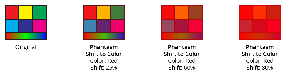
Phantasm Shift to Color Example
Illustrator Location:
Advanced Toolbar > Stylism Stack > AG Block Shadow
When the tool is hovered close to or over an art object that can accept an AG Block Shadow effect (but does not currently have one), it will automatically preview the shadow as it would generally appear using the current panel parameters. The art does not need to be selected. The type of preview depends on the tool preference settings. The default preview is a full one, showing the solid fill of the shadow in the specified color (however, the preview will not show gradients or patterns when the object has such a fill and the preference Shadow Adopts Artwork Fill Color is enabled). Previews are based on the shape of the base artwork, and will not reflect any existing live effects that might change that shape.
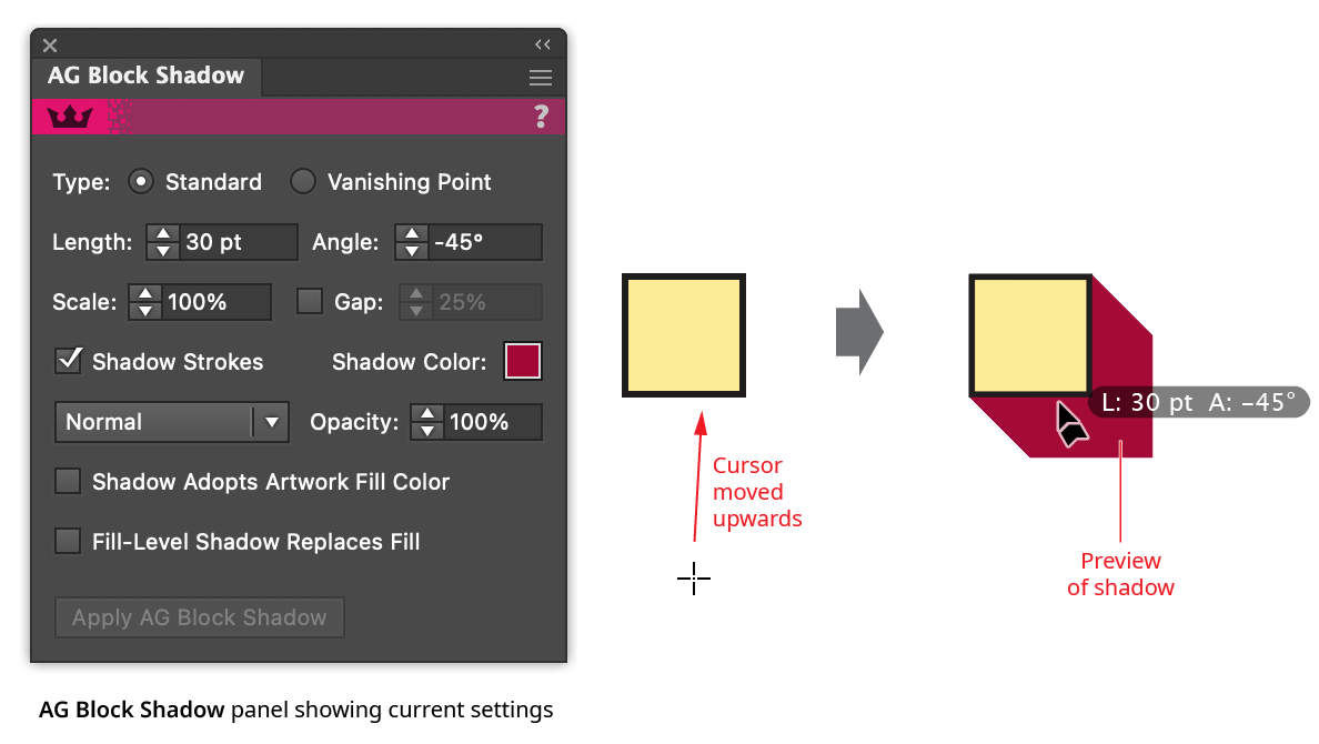
AG Block Shadow Tool Preview
By default, annotated text by the cursor will show the shadow’s length (abbreviated as “L:”), angle (as “A:”), and scale (as “S:”; omitted if it is set to the default 100%); if the shadow is a Vanishing Point type shadow, the vanishing point’s coordinates are annotated in place of its length and angle. These annotations can be temporarily hidden by holding down the Option/Alt key. Clicking will add the block shadow to the art object (always placing the live effect below all strokes and fills in the object’s appearance), or the shadow can be dragged first to adjust it in the same way an existing block shadow would be edited (see Editing Existing Block Shadows).
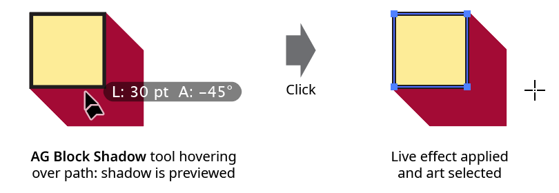
AG Block Shadow Tool Click Apply
Because the AG Block Shadow tool creates previews of shadows for any artwork it is over, selected or not, care should be taken not to pass it inadvertently over unlocked artwork with high numbers of path segments, such as large blocks of text or objects with Phantasm Halftone or Stipple effects, because calculating the shadow for these objects can take some time. In addition to keeping such art on locked layers, the preference Auto Switch To Fast Preview can help (see AG Block Shadow: Preferences).
Illustrator Location:
When the tool is hovered close to or over an existing block shadow, it can be edited with the tool. By default, a wireframe preview of the shadow will be added when the cursor is above it (and the cursor will show the length/angle/scale annotations, unless these have been disabled). Dragging the shadow will allow its length and angle to be changed.
If the shadow is of Vanishing Point type, the vanishing point will be annotated by a crosshair icon, which can be repositioned by dragging it (dragging the shadow itself also moves the vanishing point, and the shadow’s movement may not match the cursor’s). If at least one object with a Vanishing Point type shadow is selected, the tool may be Shift+Option/Alt-clicked to immediately move the vanishing point(s) to the clicked location. If multiple Vanishing Point type shadows are selected, the new location applies to all the shadows, regardless of the state of the Link Shadow Vanishing Points preference.
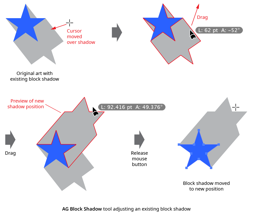
AG Block Shadow Tool Drag Edit
When the preference Edit Existing Shadows Using Original Position is enabled (the default), then a Standard type shadow is moved relative to its original position rather than being reset to zero length before being dragged.
While dragging to edit a shadow, a number of keypresses may be used:
Shift: Constrains the angle of the shadow to 45° increments around the general constrain angle (for Standard type shadows); or constrains the movement of the vanishing point to 45° increments around the general constrain angle (for Vanishing Point type shadows).
Option/Alt: For Standard type shadows, constrains the length to integer values.
Up Arrow/Down Arrow: Changes the Scale parameter by the increment value specified in the preferences (1%, by default).
Left Arrow/Right Arrow: Changes the Gap parameter by the increment value specified in the preferences (1%, by default).
1: Sets the scale to 100%.
2: Sets the scale to 200%.
5: Sets the scale to 50%.
7: Sets the scale to 75%.
0: Sets the scale to 0%.
A: Toggles on and off the tool’s cursor annotation (length, angle, and scale values).
C: Changes the wireframe color, cycling through red, blue, magenta, green, black and grey.
D: Sets the shadow to its default parameters (Standard type, 100% scale, no gap, black color, Shadow Strokes enabled; the length and angle are dependent on where the cursor is located).
G: Toggles the Gap parameter on and off.
Q: Switches the shadow preview type between Full, Wireframe, and Fast Wireframe (see AG Block Shadow: Preferences).
S: Toggles the Shadow Strokes parameter.
U: Temporarily disables Smart Guides, if they were enabled when the drag started.
X: Toggles detach mode. When true, the cursor shows a dotted line between the arrowhead and the shadow, and the shadow will be added but then immediately detached after the mouse button is released, essentially creating it as editable artwork rather than as a live effect.
The AG Block Shadow tool works on a single shadow at a time (except potentially when moving a vanishing point and the preference Link Shadow Vanishing Points is enabled), and at the highest group level. In other words, if an object is given a block shadow, and then grouped with another object, then normally the tool will not be able to edit the block shadow that is inside the group, but will instead offer to add a new block shadow at the group level. To edit the inner shadow, either isolate the grouped object (in which case the tool can be used) or edit the shadow numerically using the panel. To edit multiple shadows simultaneously, use the panel.
Illustrator Location:
Illustrator Main Menu > Window > Astute Graphics > Phantasm > Temperature/Tint
Phantasm Temperature/Tint is a photography-oriented live effect/filter that allows subtle adjustment of color temperature and tint.
As a live effect, it is accessible through the main menu, under Effect > Phantasm > Temperature/Tint. It can also be applied directly from the Appearance panel using the “Add New Effect” button at the bottom of the panel, or through the Phantasm panel (see Phantasm: Panel).
After applying the live effect using the menu item (or when clicking on the existing effect in the Appearance panel to edit it), the parameters dialog will appear:
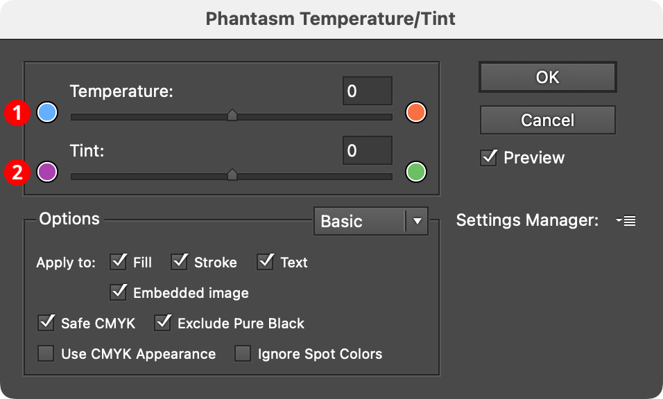
Phantasm Temperature/Tint Example
1. Temperature
Changes the “coldness” or “warmth” of artwork by adjusting the orange and blue tones. Ranges between –100 (more blue) and 100 (less blue/more orange).
2. Tint
Adjusts the red and green tones, which can be helpful for compensating for fluorescent lighting or improving natural tone such as skin and greenery. Ranges between –100 (less green) and 100 (more green).
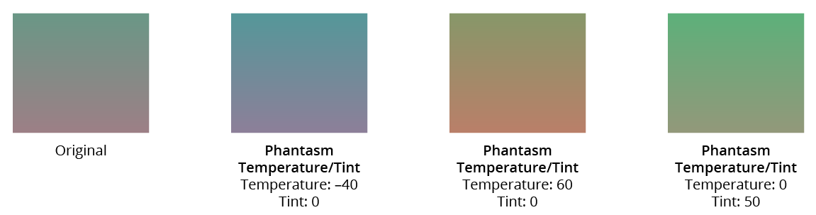
Phantasm Temperature/Tint Example
Illustrator Location:
Illustrator Main Menu > Window > Astute Graphics > AG Block Shadow
The AG Block Shadow live effect does not have a modal parameters dialog, but is instead edited using either the AG Block Shadow tool (for many parameters) or its panel (for complete control over all its parameters). The AG Block Shadow panel can be shown and hidden using the menu item found in the main menu at Window > Astute Graphics > AG Block Shadow. When at least one selected object has the AG Block Shadow live effect applied, the panel controls will update to reflect the parameters of those effects, which can then be edited. A value field which is blank or (for checkboxes) with a dash indicates that the parameter has different values in the selection. These can be unified (made the same) by entering a new value.
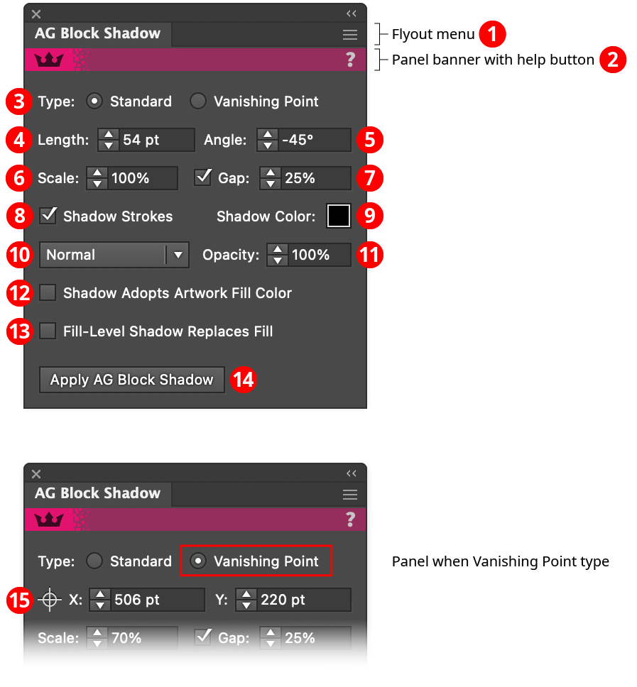
AG Block Shadow Panel
1. Flyout menu
See AG Block Shadow Panel: Flyout Menu.
2. Panel banner
The help button on the right opens the help documentation in the Astute Manager. If this does not automatically appear, please ensure your Astute Manager is running first.
3. Type
This control is only visible when the panel is in advanced mode (the panel flyout menu item Show Advanced Parameters has been chosen, or an AG Block Shadow effect using one of those advanced parameters is in the current selection). The radio buttons allow a choice between a Standard block shadow (specified by length and angle) and a Vanishing Point block shadow, which is specified through the coordinates of the vanishing point, the point to which the shadow appears to converge.
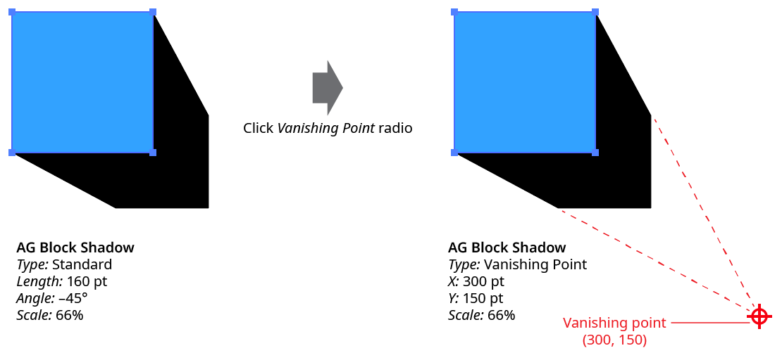
AG Block Shadow Type Example
Shadows can be freely converted between Standard and Vanishing Point, except when a Standard shadow has a Scale value of 100%, since this would imply a vanishing point at infinite distance. The advantage of a Vanishing Point type shadow is that the shadow’s point of convergence remains the same even if the object or objects to which the effect is applied are subsequently moved.
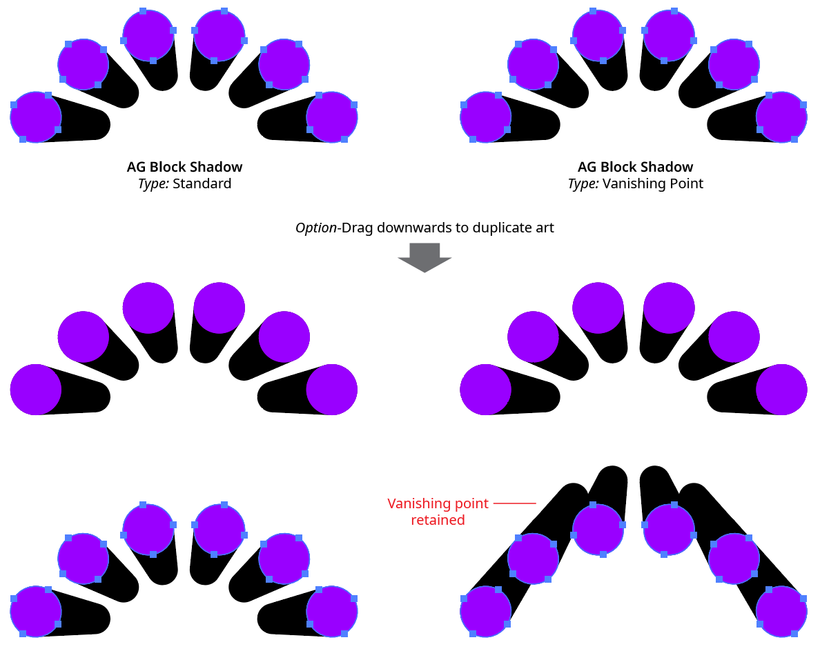
AG Block Shadow Standard vs. Vanishing Point
Tip: To move an object with a Vanishing Point type shadow and also move its vanishing point, convert the shadow to Standard type, move the object, and then convert back to Vanishing Point.
4. Length
For Standard type shadows, the nominal length of the shadow (distance from the edge of the object to the edge of the shadow, in the direction of the shadow). The default value is 72 pt. The length parameter is equal to the actual shadow length only when the shadow has no gap and the scale is set to 100%. Otherwise, the actual length may vary.
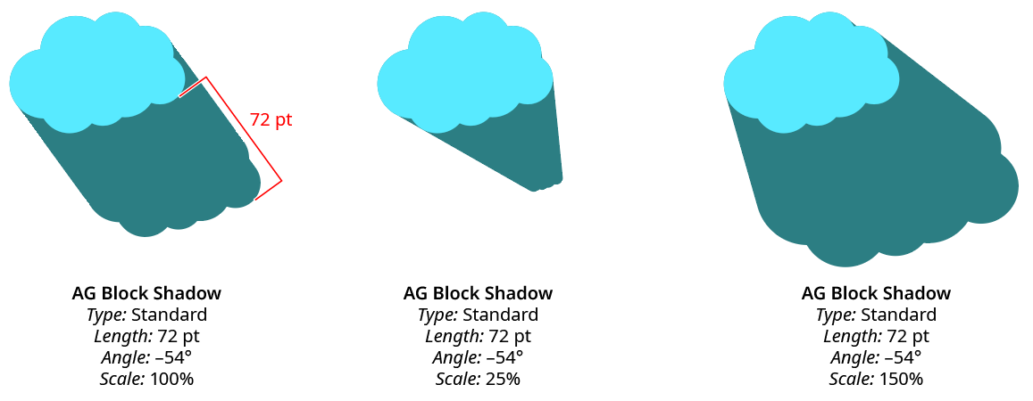
AG Block Shadow Length Comparison
5. Angle
For Standard type shadows, the angle of the shadow, specified using the normal Illustrator angle convention (to the right is 0°, with positive values going counterclockwise). The default value is –45°.
6. Scale
Specifies the relative size of the shifted shape that forms the end of the shadow, from 0% to 10000%. Scaling is done from the center of the shifted shape’s bounding box. Vanishing Point type shadows cannot have the default scale value of 100%, since this would imply a vanishing point located at infinite distance.
7. Gap
When enabled, a gap is left between the source object and its shadow. The size of the gap is specified as a percentage, which is relative to the length of the entire shadow.
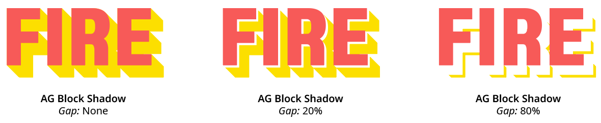
AG Block Shadow Gap Examples
8. Shadow Strokes
When enabled, shadows are cast using not only object’s stroke, but also its fill.
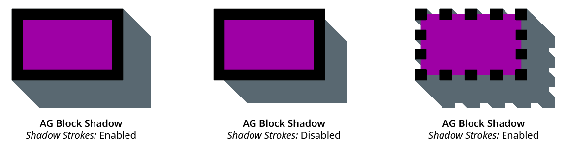
AG Block Shadow Strokes
If the stroke is dashed, shadows will be cast from each dash, as expected (but the final shadow will still be united into a single path or compound path). If a path has a stroke but no fill, then when Shadow Strokes is enabled, the shadow will be produced only from the stroke.
9. Shadow Color
The color of the shadow, unless Shadow Adopts Artwork Fill Color is enabled. Clicking the color chip will bring up the standard color picker dialog. To fill a shadow with a gradient or pattern, see the parameter Shadow Adopts Artwork Fill Color. The default Shadow Color is black.
10. Blending Mode
Specifies the blending mode of the shadow, from among the standard sixteen Illustrator blending modes. The default is Normal blending mode.
11. Opacity
Specifies the opacity of the shadow (100%, by default).
12. Shadow Adopts Artwork Fill Color
When enabled, the shadow’s color will be taken from the fill of the artwork, including gradients and patterns. If there are multiple fills, then the first one in the Appearance stacking order is used (unless the live effect is placed inside a fill, in which case that fill is used). When applied to text with differently-colored glyphs, the color of the last glyph is used. If the object has no fill, then the color is taken from the Color parameter, just as if Shadow Adopts Artwork Fill Color were not enabled.
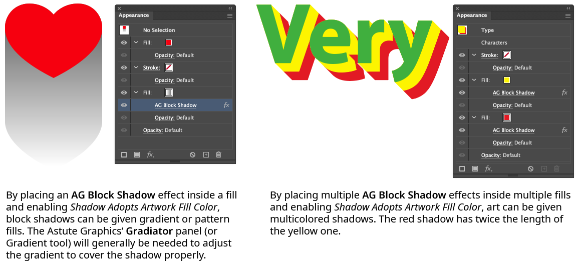
AG Block Shadow Adopt Fill Color
13. Fill-Level Shadow Replaces Fill
This control is only visible when the panel is in advanced mode (the panel flyout menu item Show Advanced Parameters has been chosen, or an AG Block Shadow effect using one of those advanced parameters is in the current selection). When enabled, and an AG Block Shadow effect has been put inside a fill in the Appearance panel, the fill from which the shadow is created is itself suppressed in the appearance. This is generally desirable unless using a block shadow with a gap because the shadow itself will also include the fill area, and an extra copy could cause undesirable results when combined with other live effects such as Boolean operations or blurs.
14. Apply Button
Click to apply the AG Block Shadow live effect to the selected artwork, with the parameters set as they currently exist in the panel. If the button is not available, then either nothing is selected or the selection already contains at least one object with an AG Block Shadow effect. If the button is clicked with Shift pressed, the shadow will be added and immediately detached, essentially creating it as editable artwork rather than as a live effect. However, this loses the ability to preview the effect first.
Illustrator Location:
Illustrator Main Menu > Window > Astute Graphics > AG Block Shadow > Panel Flyout Menu
The AG Block Shadow panel flyout menu items are contextually sensitive and all items may not be available, depending on the current selection.
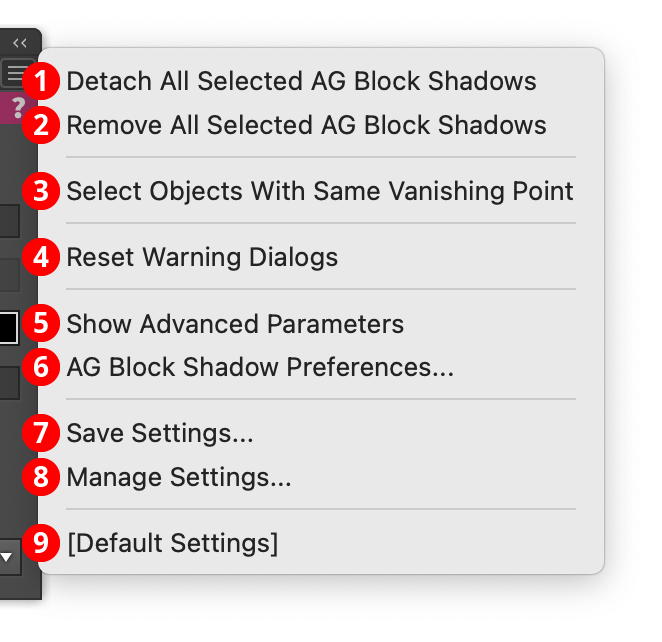
AG Block Shadow Panel Flyout Menu
1. Detach All Selected AG Block Shadows
Changes the shadows created by all AG Block Shadow live effects in the selection into editable artwork, and removes the effect from the appearance(s). This is similar to using the native menu command Object > Expand Appearance, but is more flexible because it leaves the existing artwork (and other live effects which may be present) intact.
2. Remove All Selected AG Block Shadows
Removes any AG Block Shadow live effects from the selection. (This can be done from the Appearance panel as well, but not if multiple AG Block Shadow effects are present with different parameters. In that case, the Appearance panel will simply display “Mixed Appearances” and the ability to select the live effect and delete it will no longer be available.)
3. Select Objects With Same Vanishing Point
Available if a single art object with a Vanishing Point type AG Block Shadow is selected. The menu item will select all other objects with an AG Block Shadow effect that has the same vanishing point coordinates. Different coordinates may then be entered on the panel, moving the vanishing point of all the objects together (this can also be done with the AG Block Shadow tool).
4. Reset Warning Dialogs
If one or more of AG Block Shadow’s warning dialogs (for example, the one shown when trying to use the AG Block Shadow tool in Pattern Editing Mode) have been suppressed using the Don’t show again checkbox, clicking this button will re-enable them.
5. Show Advanced Parameters
The Standard/Vanishing Point type controls and the Fill-Level Shadow Replaces Fill checkbox control are considered advanced parameters, and can be shown or hidden on the panel using this menu item. When the controls are visible, the menu item will change to Hide Advanced Parameters. If one or more objects in the current selection containing an AG Block Shadow effect that is Vanishing Point type or has Fill-Level Shadow Replaces Fill enabled, the advanced controls will automatically be shown so that the effect(s) can be properly edited.
6. AG Block Shadow Preferences...
Brings up the preference dialog (see AG Block Shadow: Preferences).
7. Save Settings...
Captures all of the current parameter settings on the panel to a file, which can be instantly recalled later (either in the current file session or a later one). A dialog will appear through which the file name may be specified.
8. Manage Settings...
Brings up a dialog through which existing settings files may be renamed or deleted:
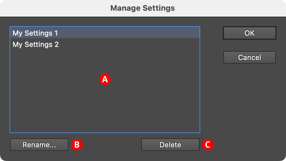
AG Block Shadow Manage Settings Dialog
A. Settings List: Shows all user-saved settings. One or more settings files can be selected for use with the buttons at the bottom of the dialog by clicking on them in the list, with Shift pressed to select contiguously or Command/Ctrl pressed to select discontiguously, as normal.
B. Rename Button: If a single settings file is selected, allows it to be renamed, through a separate dialog. If the Cancel button is used, the original names will be restored.
C. Delete Button: Removes the selected settings file(s). The files are not permanently deleted until the OK button is clicked.
9. Settings Files
User-defined settings will appear below the built-in [Default Settings] menu item. Choosing a settings menu item will load the panel with the settings it had when the file was saved; the AG Block Shadow effects in any selected art will be updated to match.
Illustrator Location:
Advanced Toolbar > Stylism Stack > AG Offset
The AG Offset tool appears in Illustrator’s main toolbar (which must be in Advanced mode: View > Toolbars > Advanced), stacked under the Stylism tool. As with other stacked tools, click and hold on the top tool icon to display the tools stacked under it.
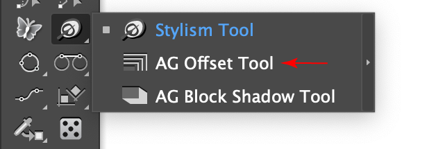
AG Offset Tool Location
The AG Offset tool’s cursor is a crosshair, except when previewing a new offset or adjusting an existing offset, in which case it appears as an arrowhead with a small group of parallel lines:
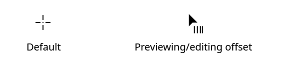
AG Offset Tool Cursors
Illustrator Location:
Advanced Toolbar > Stylism Stack > AG Offset
As the AG Offset tool has many keypresses for certain operations, we suggest installing the free Astute Graphics plugin Astute Buddy, which creates a panel that dynamically updates to inform you of the various keys which can be pressed in the tool’s current context.
The AG Offset tool is works in conjunction with the associated AG Offset panel, which generally should be open and accessible. If you are using the free Astute Graphics plugin DirectPrefs, you can have the AG Offset panel automatically be shown when the AG Offset tool is selected.
The AG Offset tool offers a graphical method for both adding and editing AG Offset live effects.
Illustrator Location:
Advanced Toolbar > Stylism Stack > AG Offset
When the tool is hovered close to or over an art object that can accept an AG Offset effect (but does not currently have one), it will automatically preview the offset as it would generally appear using the current panel parameters. The art does not need to be selected. The type of preview depends on the tool preference settings; the default preview is a full one, showing a complete trace of each offset path in the specified color (red by default, but can be changed). Previews are based on the shape of the base artwork, and will not reflect any existing live effects that might change that shape.
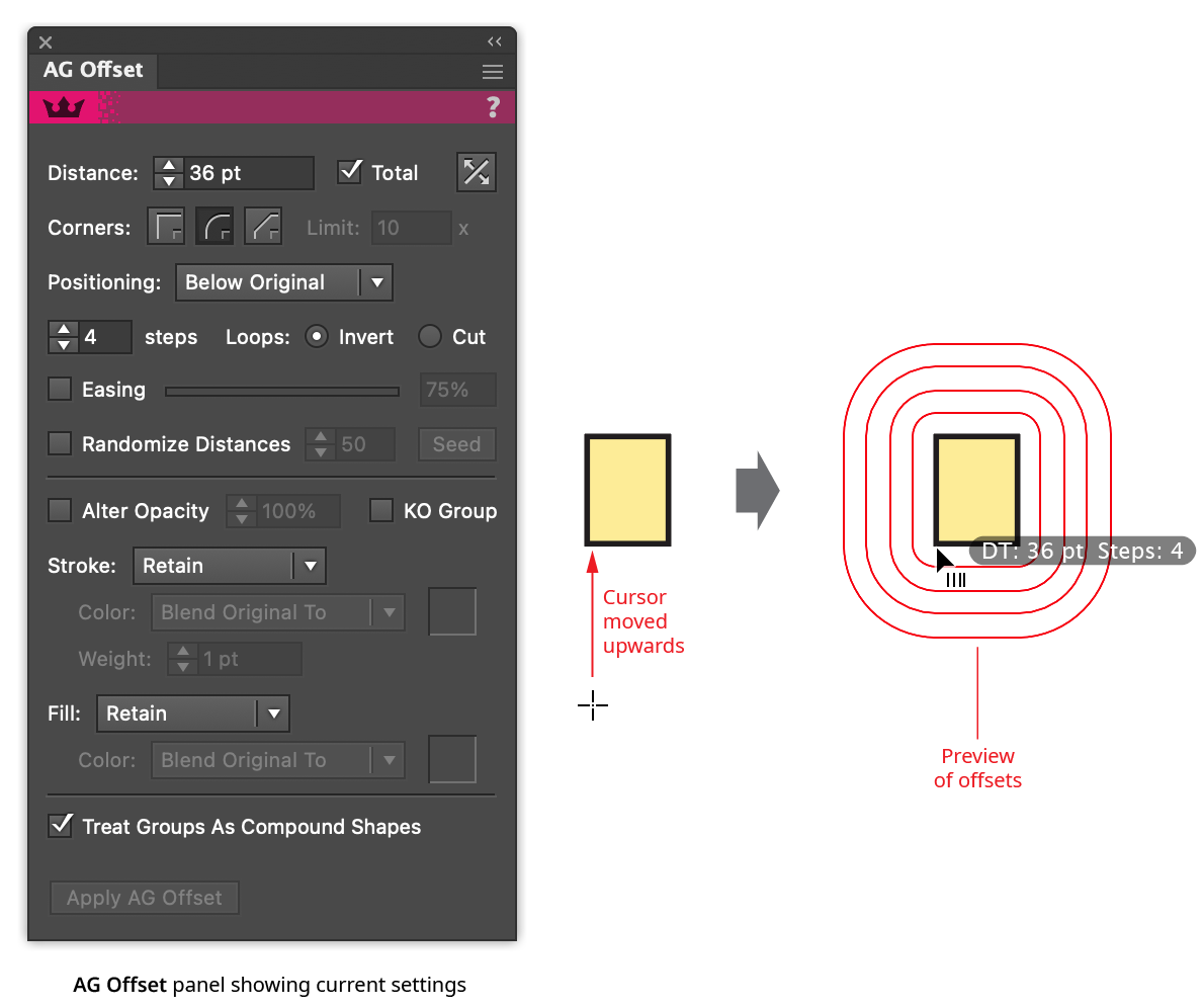
AG Offset Tool Preview
By default, annotated text by the cursor will show the offset’s distance (abbreviated as “D:”, or “DT:” if the Total parameter is enabled) and the step count. Easing, if enabled, will also be indicated. These annotations can be temporarily hidden by holding down the Option/Alt key. Clicking will add the offset effect to the art object (always placing the live effect below all strokes and fills in the object’s appearance), or the offset can be dragged first to adjust it in the same way an existing offset would be edited (see Editing Existing Offsets).
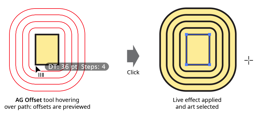
AG Offset Tool Click Apply
By default, the AG Offset tool creates previews of shadows for any artwork it is over, selected or not,
so care should be taken not to pass it inadvertently over unlocked artwork with high numbers of path segments, such as large blocks of text or objects with expanded Phantasm Halftone or Stipple effects, because calculating the offsets for these objects can take some time. In addition to keeping such art on locked layers, the preference Operate On Selected Objects Only limits the hover preview to selected objects only (see AG Offset: Preferences). If the AG Offset cursor is passed over an unlocked text object containing many characters, a warning dialog will be displayed:
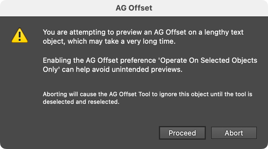
AG Offset Lengthy Text Object Warning
Click Abort unless you are sure you want to put the effect on the text object and are prepared to wait.
Illustrator Location:
Advanced Toolbar > Stylism Stack > AG Offset
When the tool is hovered close to or over an existing offset path or the original object, the existing AG Offset live effect can be edited with the tool. By default, the cursor will show the distance/steps annotations, unless these have been disabled. Dragging with the tool changes the distance parameter. When the AG Offset has multiple steps, only one of the offset paths is kept under the cursor. When the Total parameter is enabled, the last offset is kept under the cursor; otherwise the first offset is kept under the cursor.
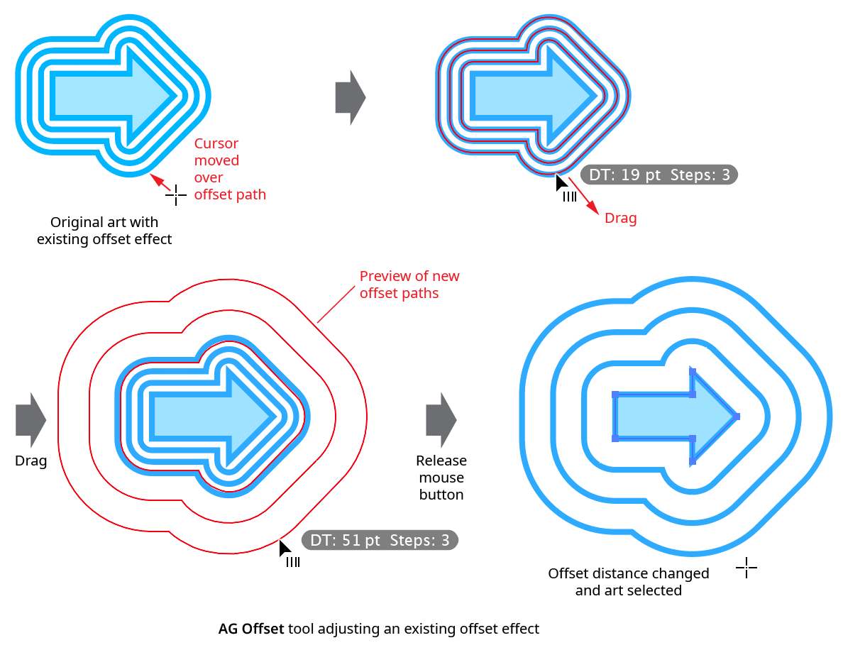
AG Offset Tool Drag Edit
While dragging to edit an AG Offset effect, a number of keypresses may be used:
Option/Alt: Constrains the distance parameter to “nice” values (integers, at 400% zoom or less).
Up Arrow/Down Arrow: Increments or decrements the Step parameter.
Left Arrow/Right Arrow: Changes the Easing parameter by 1%.
1–9: Sets the Easing parameter to 10% through 90% respectively.
A: Toggles the annotation readout on or off.
B: Toggles the Both Sides parameter on and off.
C: Changes the preview color, cycling through red, blue, magenta, green, black and grey.
D: Sets all parameters to their default values.
E: Toggles the Easing parameter on and off.
G: Toggles the Treat Groups As Compound Shapes parameter on and off.
L: Toggles the loops mode between Invert and Cut.
Q: Toggles the offset preview type between Full and Fast (see AG Offset: Preferences).
R: Available if the Step count is set to 2 or more. Toggles the Randomize Distances parameter on and off.
T: Available if the Step count is set to 2 or more. Toggles the Total parameter on and off.
U: Temporarily disables Smart Guides, if they were enabled when the drag started.
The AG Offset tool works on a single offset effect at a time, and at the highest group level. In other words, if an object is given an offset, and then grouped with another object, then normally the tool will not be able to edit the offset that is inside the group, but will instead offer to add a new offset at the group level. To edit the inner offset, either isolate the grouped object (in which case the tool can be used) or edit the offset numerically using the panel. To edit multiple offsets simultaneously, use the panel.
Illustrator Location:
Illustrator Main Menu > Window > Astute Graphics > AG Offset
The AG Offset live effect does not have a modal parameters dialog, but is instead edited using either the AG Offset tool (for many parameters) or its panel (for complete control over all its parameters). The AG Offset panel can be shown and hidden using the menu item found in the main menu at Window > Astute Graphics > AG Offset. When at least one selected object has the AG Offset live effect applied, the panel controls will update to reflect the parameters of those effects, which can then be edited. A value field which is blank or (for checkboxes) with a dash indicates that the parameter has different values in the selection. These can be unified (made the same) by entering a new value.
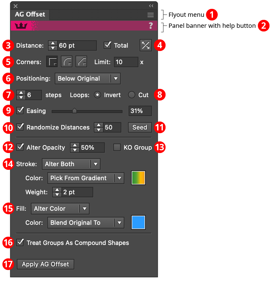
AG Offset Panel
1. Flyout menu
See AG Offset Panel: Flyout Menu.
2. Panel banner
The help button on the right opens the help documentation in the Astute Manager. If this does not automatically appear, please ensure your Astute Manager is running first.
3. Distance
Specifies the base offset distance. When more than one offset is being created (i.e., the number of Steps is set to 2 or higher), the Total checkbox controls whether the value represents the total of all offsets or the value of each offset. Easing and Randomize Distance, if enabled, will affect the final actual offset distances. Positive values represent outwards offsets (for closed paths); or offsets to the righthand side of the path (for open paths, in relation to the direction of the path).
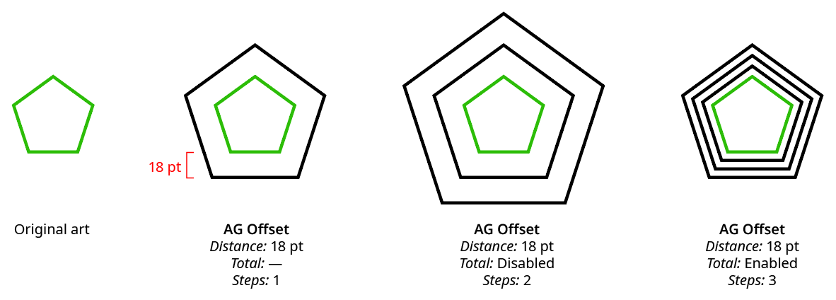
AG Offset Distance Example
4. Both Sides Button
When toggled to the enabled state (dark), the path(s) will be offset both inwards and outwards.
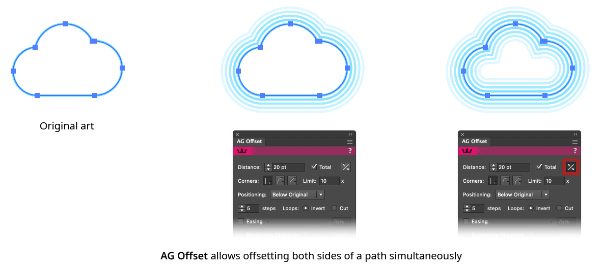
AG Offset Both Sides Example
5. Corner Type
The type of corner to use when offset outwards from a sharp corner on a path, from among the three standard Illustrator corner types (Mitered, Rounded, and Beveled). When set to Mitered, the Miter Limit may be specified.
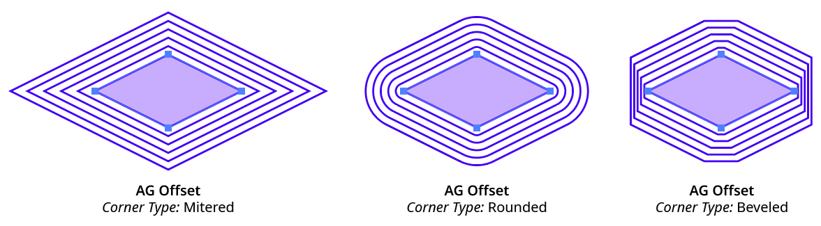
AG Offset Corner Types
6. Positioning
Specifies the position of the offset paths in relation to the original path, from among Above Original, Replace Original, or Below Original.
7. Steps
The number of offsets to make, from 1 to 999 (if the Both Sides setting is enabled, the value applies to each side independently).
8. Loops
This setting is only applicable when there are loops in open paths into which the offset path cannot fit. It specifies the method used to deal with such loops. The default value is Invert, where the offset path runs on the opposite side of the loop, but can be changed to Cut, in which case the loop is “cut” from the path, essentially ignoring it.
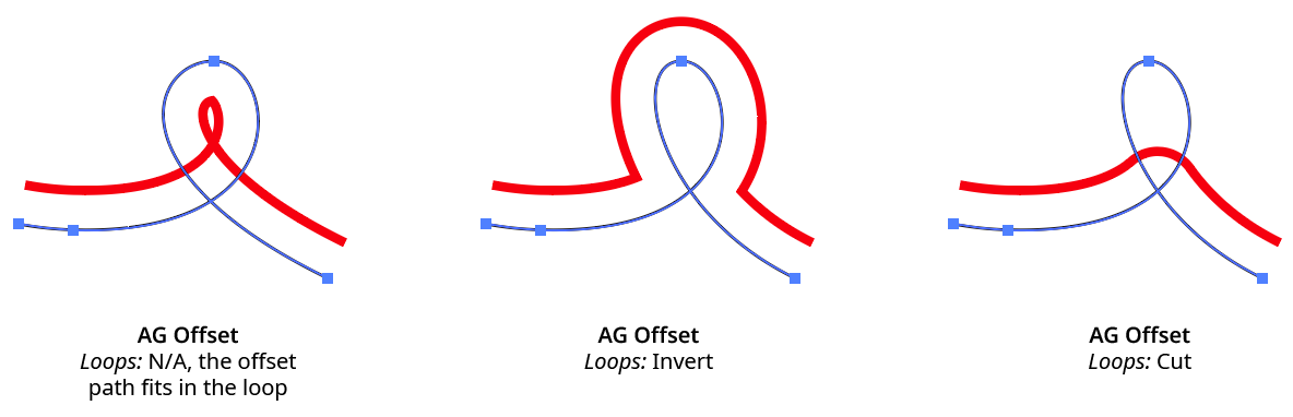
AG Offset Loop Handling
9. Easing
When multiple steps are used, Easing causes them to become progressively larger (for values less than 50%) or progressively smaller (for values larger than 50%). In both cases, the Distance value applies to the first offset only.
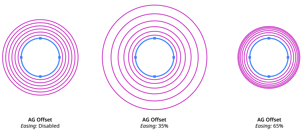
AG Offset Easing Example
10. Randomize Distances
When enabled, distances between multiple offsets are randomly changed. The specified value (from 1 to 100) controls how much variation is allowed, where 100 is maximum variation.
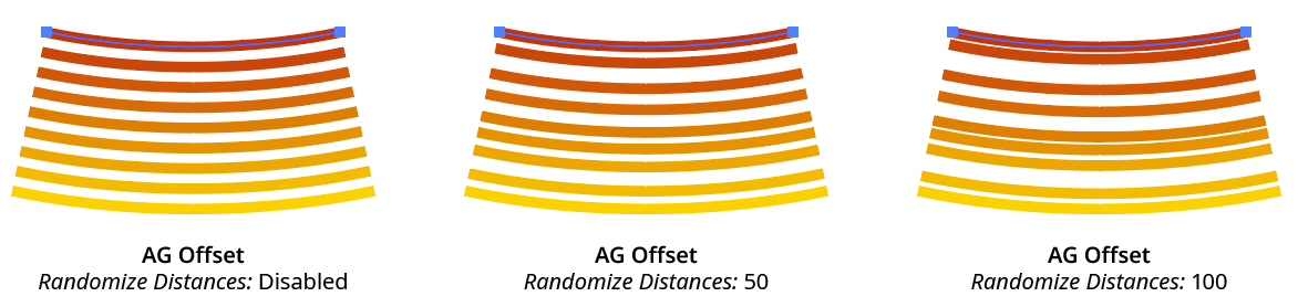
AG Offset Randomize Example
11. Seed
Each random seed number leads to a different sequence of random values. Clicking the button picks a new seed, thereby changing the look of the artwork. To view or specify the seed number directly, Option/Alt-click the button. This lets you recreate a previously-generated look.
12. Alter Opacity
When enabled, the opacity of the offset path is changed to the specified value. If multiple offsets are being used, their opacities are linearly blended between the opacity of the original art and the specified value. For example, if the original art had 100% opacity and the Alter Opacity value was set to 50%, and Steps was set to 4, then the offset paths would have opacities of 88%, 75%, 63%, and 50%.
13. KO [Knockout] Group
When enabled, this setting keeps multiple, partially-transparent offset paths from being transparent to each other, just as the Knockout Group setting on the native Transparency panel does.
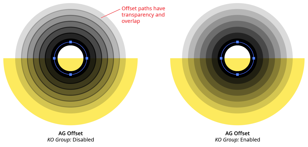
AG Offset Knockout Group Example
14. Stroke
When the AG Offset live effect is located below the fill and strokes of the artwork in the Appearance panel, this pulldown menu specifies how the stroke of the offset path should be handled:
Retain means the stroke (if any) will be simply be taken from the original path.
Remove means the offset paths will have no stroke, even if the original path had one.
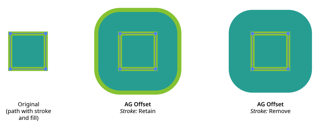
AG Offset Stroke Retain and Remove
Alter Color means the offset path (if it has a stroke), will have its stroke color changed. There are two methods for doing so, specified by the pulldown menu that will become active. When set to Blend Original To, the last offset will have its color changed to the specified color (clicking the color chip allows changing the color using the standard Color Picker); if there are multiple offset paths, the paths will take colors which blend from the original stroke color to the specified color. When set to Pick From Gradient, the stroke colors of the offset paths will be taken from the specified gradient, with the first path corresponding to the color at the start of the gradient and the last offset path corresponding to the color at the end of the gradient.
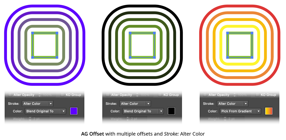
AG Offset Stroke Alter Color
Alter Weight means the offset path (if it has a stroke), will have its stroke weight changed to the specified value. If there are multiple offset paths, the paths’ strokes will be assigned weights which blend from the original stroke weight to the specified weight.
Alter Both allows changing both the color (as per Alter Color) and weight (as per Alter Weight) of the offset paths’ strokes.
Force means the color and weight of the offset path’s stroke will be set to whatever is specified, regardless of the original path’s style. This is useful for adding a stroked outline to fill-only art without having to add a stroke to the art and moving the AG Offset live effect inside the stroke with the Positioning set to Replace Original.
15. Fill
When the AG Offset live effect is located below the fill and strokes of the artwork in the Appearance panel, this pulldown menu specifies how the fill of the offset path should be handled:
Retain means the fill (if any) will be simply be taken from the original path.
Remove means the offset paths will have no fill, even if the original path had one.
Alter Color means the offset path (if it has a fill), will have its fill color changed. There are two methods for doing so, specified by the pulldown menu that will become active. When set to Blend Original To, the last offset will have its color changed to the specified color (clicking the color chip allows changing the color using the standard Color Picker); if there are multiple offset paths, the paths will take colors which blend from the original fill color to the specified color. When set to Pick From Gradient, the fill colors of the offset paths will be taken from the specified gradient, with the first path corresponding to the color at the start of the gradient and the last offset path corresponding to the color at the end of the gradient.
Force means the color of the offset path’s fill color will be set to whatever is specified, regardless of the original path’s style.
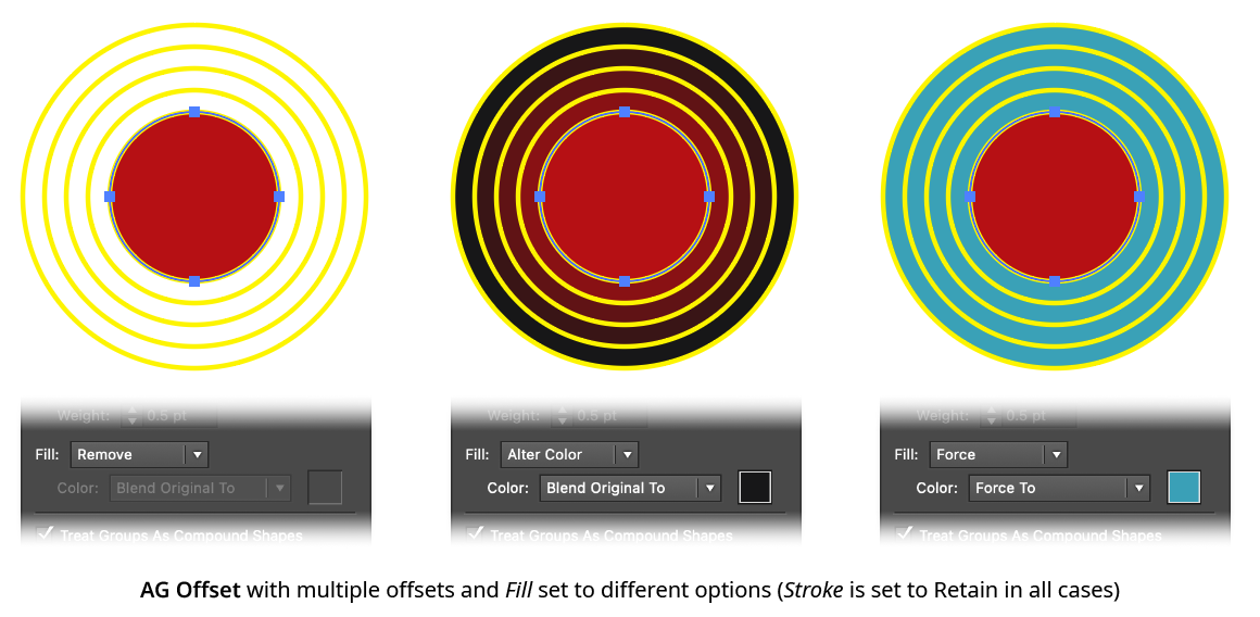
AG Offset Fill Options
16. Treat Groups As Compound Shapes
When enabled, and the effect is applied to a group (or art that is internally expanded into a group within the effect stack, such as live text), the offset paths are created as if the members of the group were united into a single compound shape:
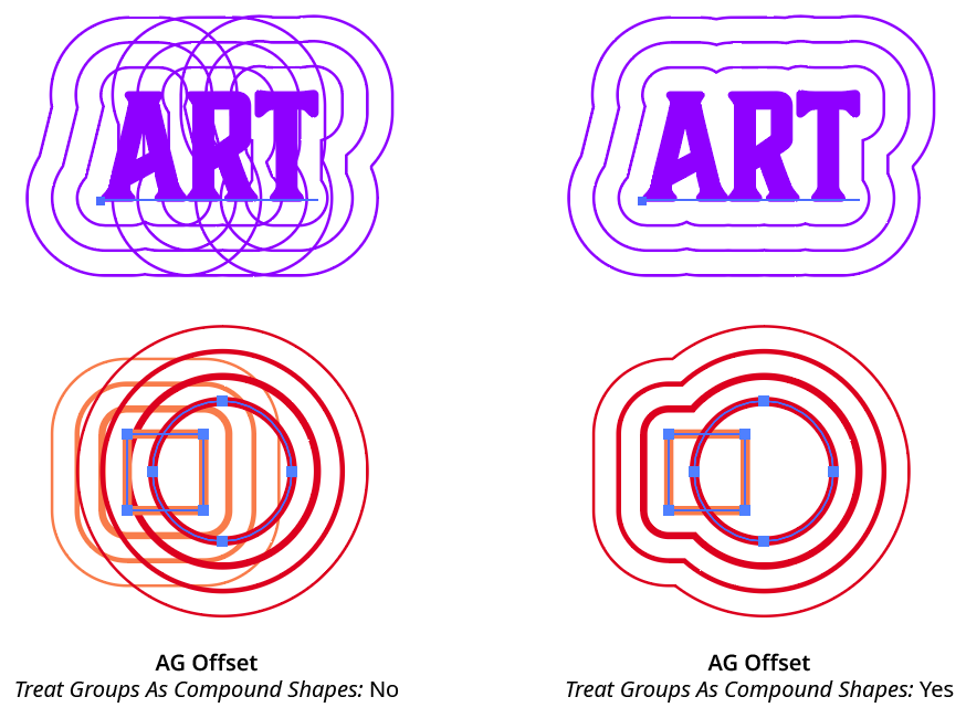
AG Offset Treat Groups as Compound Shapes
17. Apply Button
Click to apply the AG Offset live effect to the selected artwork, with the parameters set as they currently exist in the panel. If the button is not available, then either nothing is selected or the selection already contains at least one object with an AG Offset effect. If the button is clicked with Shift pressed, the offset paths will be added and immediately detached, essentially creating them as editable artwork rather than as a live effect. However, this loses the ability to preview the effect first.
Illustrator Location:
Illustrator Main Menu > Window > Astute Graphics > AG Splatter
AG Splatter is an Astute Graphics live effect that adds randomly-generated splatter or spatter type objects along the paths of the art to which it is applied. A panel interface allows adjustment of many parameters, such as the splatters’ shape, angle, offset, and more. AG Splatter is part of the Stylism plugin.
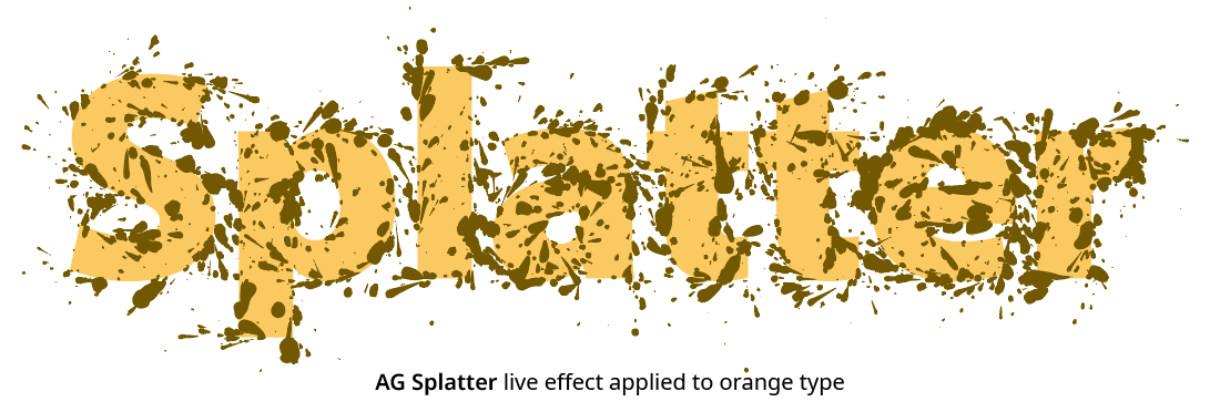
AG Splatter Example
As with most live effects, AG Splatter appears in the main menu, under Effect > Stylism > AG Splatter. It can also be applied directly from the Appearance panel using the “Add New Effect” button at the bottom of the panel. However, the easiest way to apply the live effect is using the Apply button on the AG Splatter panel.
Illustrator Location:
Illustrator Main Menu > Window > Astute Graphics > AG Splatter
The AG Splatter live effect does not have a modal parameters dialog, but is instead edited using a panel, which can be shown and hidden using the menu item found in the main menu at Window > Astute Graphics >AG Splatter. When at least one selected object has the AG Splatter live effect applied, the panel controls will update to reflect the parameters of those effects, which can then be edited. A value field which is blank or (for checkboxes) with a dash indicates that the parameter has different values in the selection. These can be unified (made the same) by entering a new value.
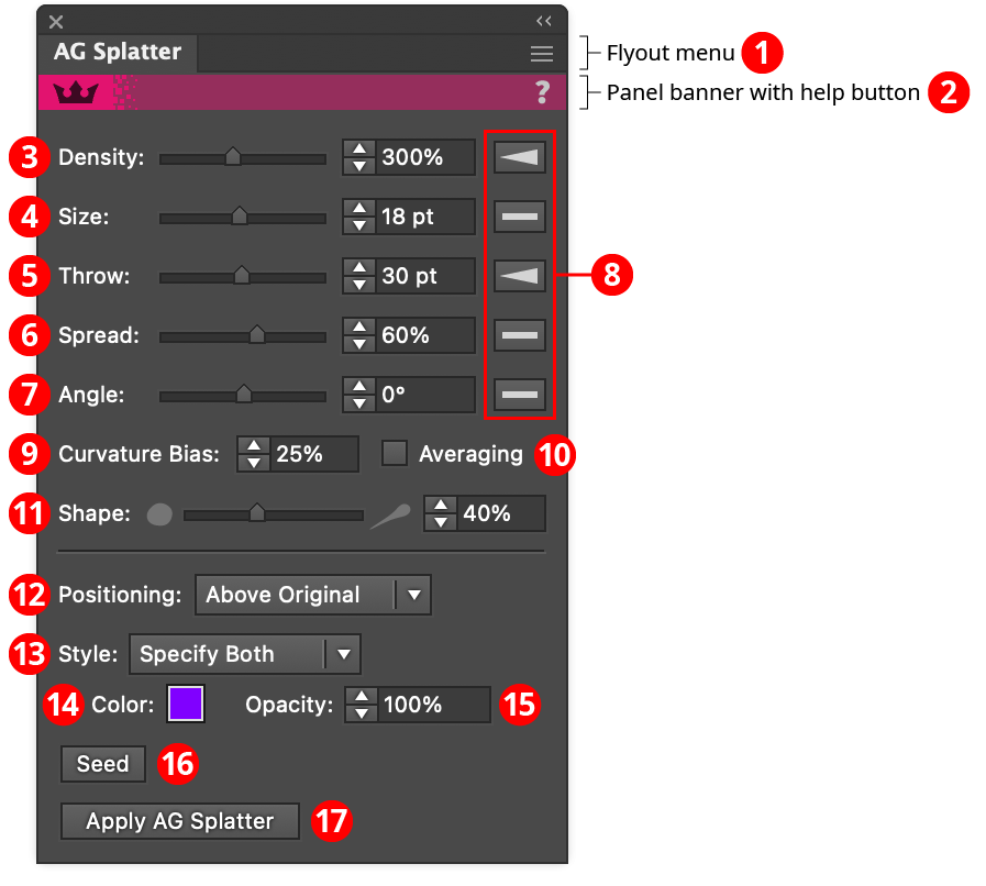
AG Splatter Panel
1. Flyout menu
See AG Splatter Panel: Flyout Menu.
2. Panel banner
The help button on the right opens the help documentation in the Astute Manager. If this does not automatically appear, please ensure your Astute Manager is running first.
3. Density
Controls the relative number of splatter “droplets” that are created along the path; it can range from 0.1% to 99999.9%. A value of 100% (the default) nominally produces 100 droplets along a 1000 pt long straight path, so therefore a Density value of 800% would produce 800. However, as with all parameters, the actual count will randomly fall within a Gaussian (normal) distribution around this value. Additionally, if the path has tight curves and the Curvature Bias parameter is set to a high value, then the count will be increased, potentially by tenfold or even more.
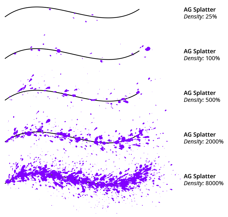
AG Splatter Density Examples
If the Density is set to a value that would produce a very large number of droplets (on the order of 100,000), a warning dialog will be displayed:
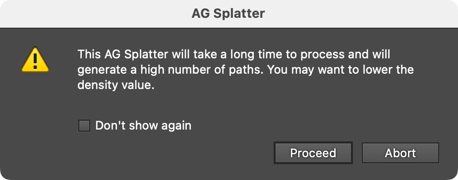
AG Splatter Long Processing Time Warning
Pressing the Abort button will stop execution of the live effect, allowing you to lower the Density without waiting for the effect to finish processing. If the Don’t show again checkbox is enabled, the dialog can be re-enabled using the Reset Warning Dialog menu item in the panel’s flyout menu.
4. Size
Controls the approximate size of the splatter droplets. However, splatter Size is not absolute but randomly assigned and also dependent on both the throw distance and the angle from the path; long distances produce smaller splatters, as do higher angles. Size can vary from 0pt to 500pt, with a default of 6pt.
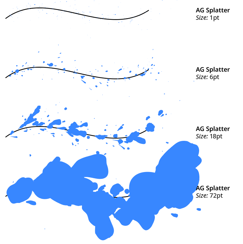
AG Splatter Size Examples
5. Throw
Controls the average distance that the splatter droplets are shifted from their point of origin along the path, from 0pt to 1000pt and a default value of 16pt.
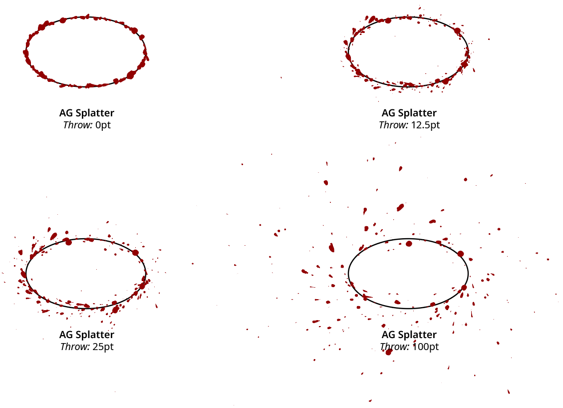
AG Splatter Throw Examples
6. Spread
Controls the range in angles that the splatter droplets are “thrown” away from the tangent angle of the path at the point of origin, from 0% to 100% with a default value of 50%.
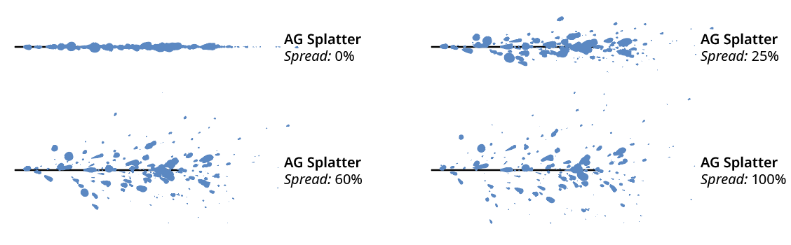
AG Splatter Spread Examples
7. Angle
Controls an overall change in the throw angle of the splatter droplets, from –90° to 90° (where positive values rotate the splatters counterclockwise). This can be used to put the splatters more towards one side of a path instead of equally on both sides, which is the default.
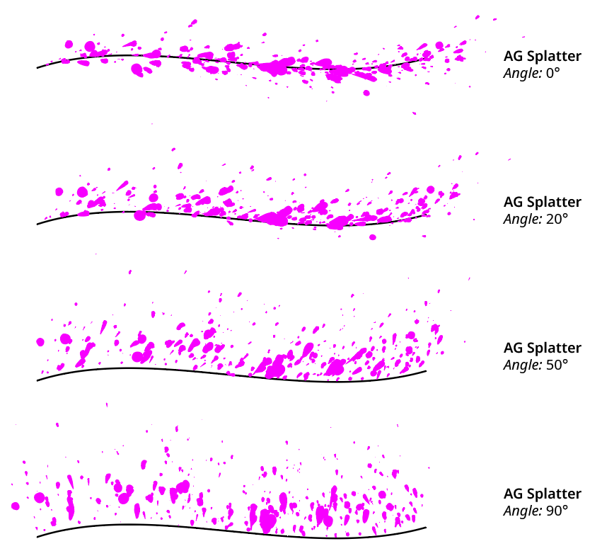
AG Splatter Angle Examples
8. Parameter Profile Buttons
Specify how the respective parameter changes as the splatters are created from one end of the path to the other. There are five options:
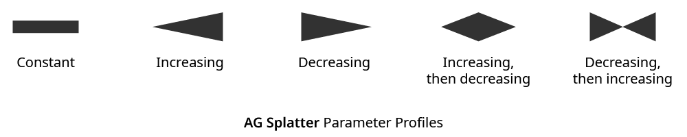
AG Splatter Parameter Profile Types
When a parameter increases, it moves linearly from zero to the value that is specified, and when it decreases, it does to zero. Thus, for example, an Increasing then Decreasing Size set to 40pt would create splatters with size zero at the start of the path, increase to size 40pt at the midpoint of the path, and then decrease to zero again at the end of the path. The default profile is Constant.

9. Curvature Bias
Specifies how much sharp curves on the path act to increase the number of splatters. A value of 0% means that curved sections of the path are treated no differently from straight sections. Higher Curvature Bias values will make more splatters appear at curved sections of the path, with sharper curves getting more splatters. The default value is 50%.
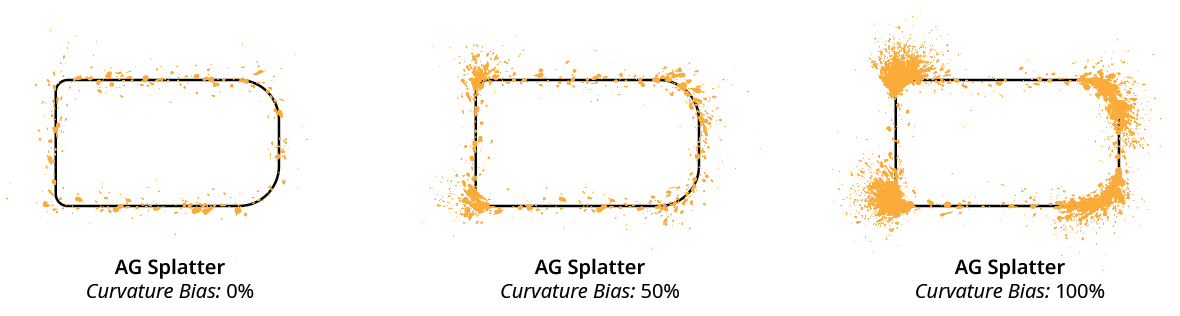
AG Splatter Curvature Bias Examples
10. Averaging
When Curvature Bias is enabled, Averaging uses a moving average of the path’s curvature rather than its instantaneous value at any spot. This can help stop unwanted high numbers of splatters from being created when effects such as Roughen (which cause the path the bend sharply) are applied above the AG Splatter effect in the Appearance panel. The default setting is on.
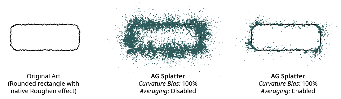
AG Splatter Averaging Examples
11. Shape
Controls the mix of splatter droplet shapes, with 0% representing rounded droplets on the left, to 100% representing narrow, teardrop-shaped droplets on the right. The default value is 30%.
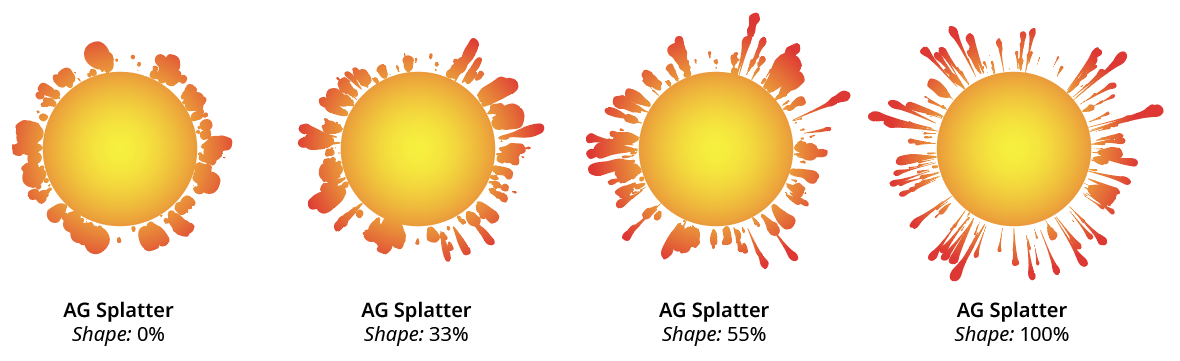
AG Splatter Shape Examples
12. Positioning
Specifies the position of the splatter droplets in relation to the original path, from among Above Original, Replace Original, or Below Original.
13. Style
When the AG Splatter live effect is located below the fill and strokes of the artwork in the Appearance panel, the Style pulldown menu specifies how the fill color and opacity of the created splatter droplets should be determined:
Use Original means the fill will be simply be taken from the original path (if the original path has no fill, then it is taken from its stroke). This fill can be a flat color, a gradient, or a pattern.
Specify Color means the fill color of the droplets is specified using the Color control underneath.
Specify Opacity means the opacity of the droplets is specified using the Opacity control underneath.
Specify Both means both the fill color and opacity of the droplets are specified using the controls underneath.
14. Color
Available if the Style is set to Specify Color or Specify Both; it specifies the fill color of the splatter droplets. Clicking the color chip will bring up the standard color picker dialog. The default Color is black.
15. Opacity
Available if the Style is set to Specify Opacity or Specify Both; it specifies the fill opacity of the splatter droplets. Low opacities can be used to create cloud-type effects.
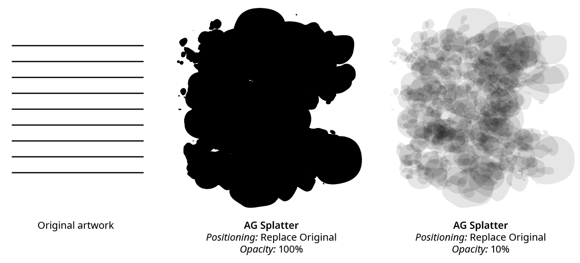
AG Splatter Opacity Examples
16. Seed
Each random seed number leads to a different sequence of random values. Clicking the button picks a new seed, thereby changing the look of the artwork. To view or specify the seed number directly, Option/Alt-click the button. This lets you recreate a previously-generated look.
17. Apply Button
Click to apply the AG Apply live effect to the selected artwork, with the parameters set as they currently exist in the panel. If the button is not available, then either nothing is selected or the selection already contains at least one object with an AG Splatter effect. If the button is clicked with Shift pressed, the splatter droplets will be added and immediately detached, essentially creating them as editable artwork rather than as a live effect. However, this loses the ability to preview the effect first.
Illustrator Location:
The following operation can be recorded and played back as an Action:
1. The menu item Select > AG Splatter Effects.
Illustrator Location:
Illustrator Main Menu > Window > Astute Graphics > AG Curvature Visualizer
AG Curvature Visualizer is an Astute Graphics live effect for paths or live text that adds a sequence of abutting thin polygons (the visualization art, or “curvature comb”) along the edge of each path. The polygons are oriented perpendicularly to the convex side of the path, and each polygon’s color reflects the curvature of the path at the spot adjacent to the polygon’s base. While AG Curvature Visualizer can be used for creative purposes, it is most useful in areas such as font design for easily visualizing curvature discontinuities, which generally manifest themselves as “lumpiness” in the curves. A panel interface allows adjustment of several parameters, such as the color, quality, and opacity of the curvature comb. AG Curvature Visualizer is part of the Stylism plugin.
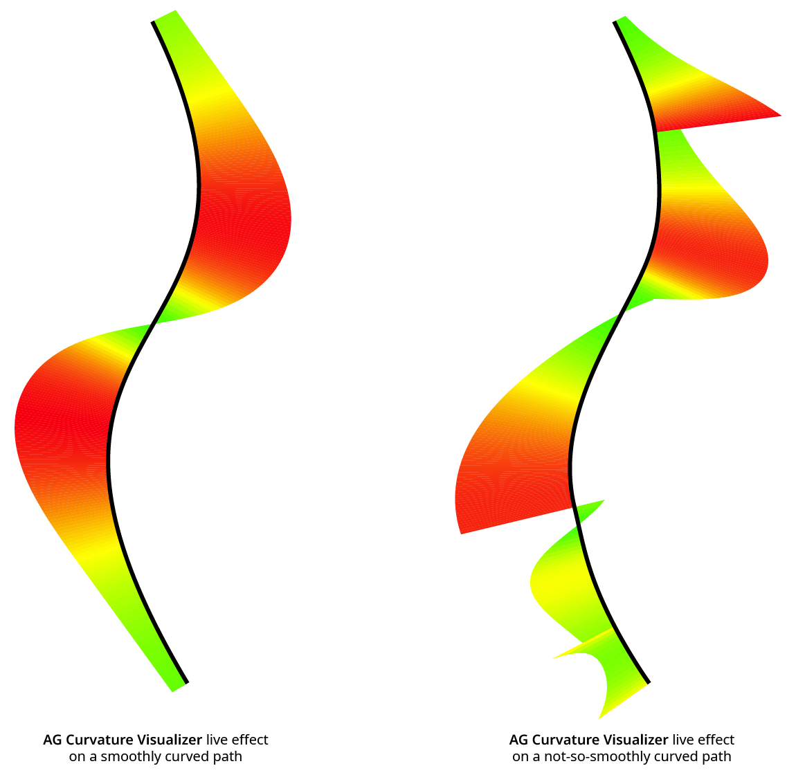
AG Curvature Visualizer Example
As with most live effects, AG Curvature Visualizer appears in the main menu, under Effect > Stylism > AG Curvature Visualizer. It can also be applied directly from the Appearance panel using the “Add New Effect” button at the bottom of the panel. However, the easiest way to apply the live effect is using the Apply button on the AG Curvature Visualizer panel.
Illustrator Location:
Illustrator Main Menu > Window > Astute Graphics > AG Curvature Visualizer
The AG Curvature Visualizer live effect does not have a modal parameters dialog, but is instead edited using a panel, which can be shown and hidden using the menu item found in the main menu at Window > Astute Graphics > AG Curvature Visualizer. When at least one selected object has the AG Curvature Visualizer live effect applied, the panel controls will update to reflect the parameters of those effects, which can then be edited. A value field which is blank or (for checkboxes) with a dash indicates that the parameter has different values in the selection. These can be unified (made the same) by entering a new value.
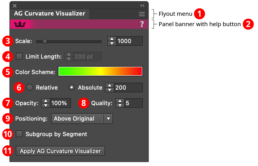
AG Curvature Visualizer Panel
1. Flyout menu
See AG Curvature Visualizer Panel: Flyout Menu.
2. Panel banner
The help button on the right opens the help documentation in the Astute Manager. If this does not automatically appear, please ensure your Astute Manager is running first.
3. Scale
Controls the overall height of the curvature comb. The curvature along the path is multiplied by the Scale factor to determine the height of each polygon (which may then be changed by the Limit Length setting; also, there is a hard limit of 8000 pt regardless of whether Limit Length is enabled or not, because otherwise the length would go to infinity at cusps, where the radius of curvature goes to zero). As the curvature is the reciprocal of the radius of curvature, it follows that a 50 pt radius circle would have a curvature of 1/50, so if the Scale were set to 1000 (the default), the comb would be 1/50 × 1000 = 20 pt high. Scale may be set from 1 to 10000.
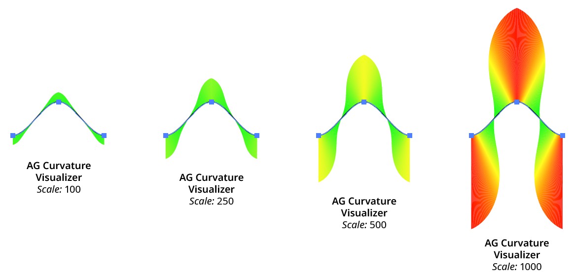
AG Curvature Visualizer Scale Examples
4. Limit Length
Puts a limit on the length of the polygons that make up the curvature comb. This allows the use of a fairly high Scale value (so areas of low curvature are visible) without making the comb extend well beyond the bounds of the screen at areas of high curvature. When the length is limited using this setting, colors are not affected (as colorization is based on pre-limited length).
5. Color Scheme
Allows you to specify the colors of the polygons which correspond to the underlying curvatures. The default scheme is green (low curvature) to yellow to red (high curvature). Clicking the preview area will bring up a dialog allowing you to choose an existing eligible gradient to define the color scheme.
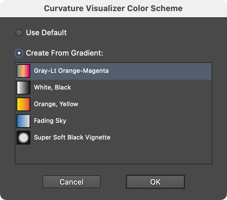
AG Curvature Visualizer Color Scheme Dialog
Color schemes are limited to 8 color stops, so gradients with more than 8 stops are not eligible and will not appear in the list.
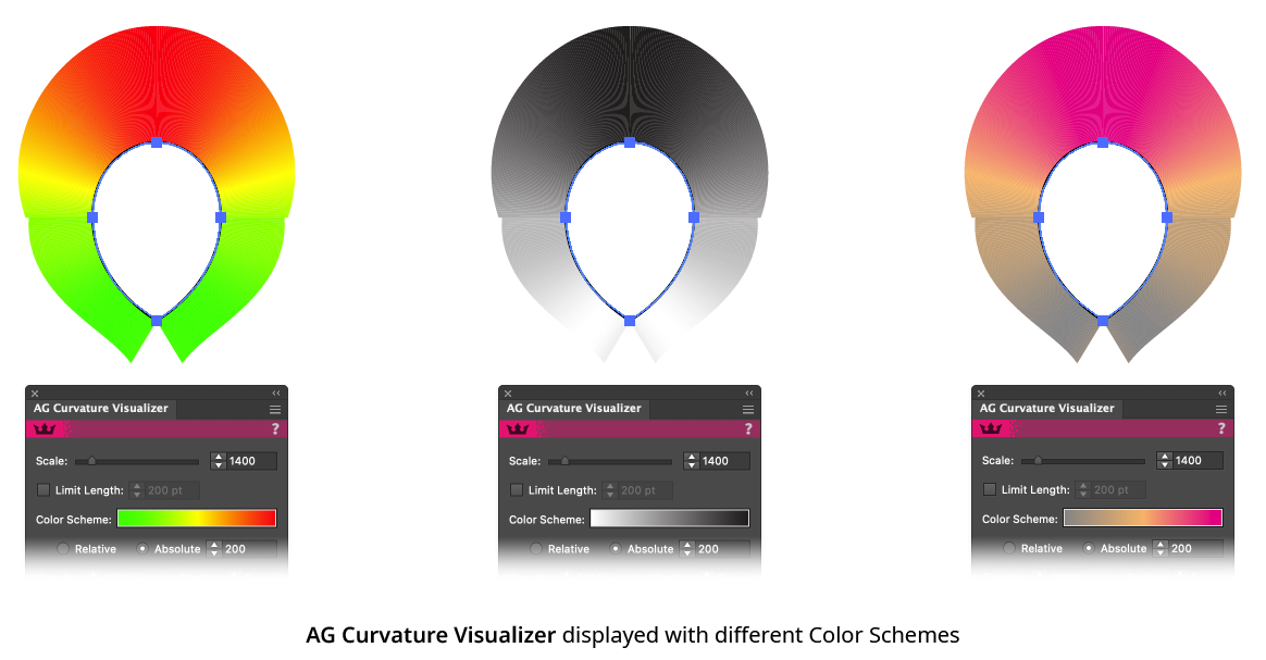
6. Relative/Absolute Mode
Specifies how the colors in the color scheme are mapped to the curvature values of the path. In Relative mode, the start color is mapped to the path’s minimum curvature, and the end color is mapped to the path’s maximum curvature. This makes even small variations in curvature clearly distinguishable (for example, it shows that a circle created from cubic bezier curves actually varies in radius slightly). In Absolute mode, the start color is mapped to zero curvature, and the end color is mapped to the specified scaled curvature. With an appropriate color scheme, this might be useful for identifying areas along a path where the radius of curvature is below a certain threshold.
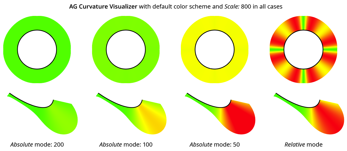
AG Curvature Visualizer Relative vs. Absolute
7. Opacity
Specifies the opacity of the curvature comb polygons.
8. Quality
Controls the number of polygons used to make up the curvature comb. Quality can range from 1 to 10, with a default of 5. Higher values result in smoother color transitions and curved edges, but will be slower because more paths are internally generated.
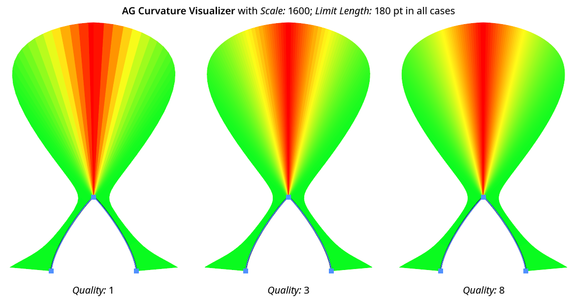
AG Curvature Visualizer Quality Examples
9. Positioning
Specifies the position of the curvature comb polygons in relation to the original path, from among Above Original, Replace Original, or Below Original.
10. Subgroup by Segment
When enabled, the curvature comb polygons along each segment of the path are grouped separately instead of being in a single group. This is useful when the curvature combs overlap each other; setting the Opacity is to something less than 100% will enable you to see the comb sections which are underneath others, as opacity is applied to each group separately.
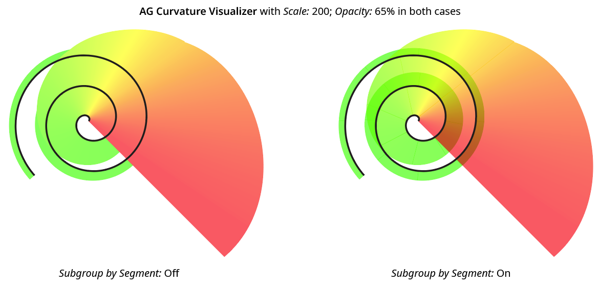
AG Curvature Visualizer Subgroup by Segment
11. Apply Button
Click to apply the AG Curvature Visualizer live effect to the selected artwork, with the parameters set as they currently exist in the panel. If the button is not available, then either nothing is selected or the selection already contains at least one object with an AG Curvature Visualizer effect. If the button is clicked with Shift pressed, the curvature comb polygons will be added and immediately detached, essentially creating them as editable artwork rather than as a live effect. However, this loses the ability to preview the effect first.
Illustrator Location:
The menu item to show and hide the Live Effect Parameter Editor panel can be found in the main menu under Window > Astute Graphics > Live Effect Parameter Editor.
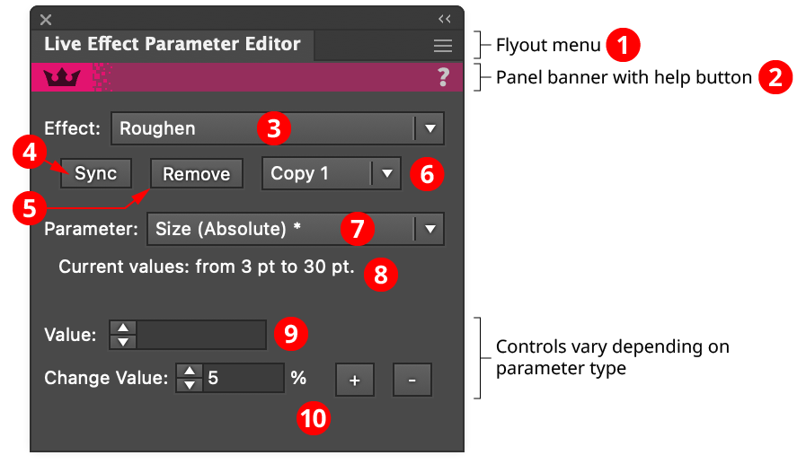
Live Effect Parameter Editor Panel
1. Flyout Menu
See Live Effect Parameter Editor Panel: Flyout Menu.
2. Panel Banner
The Live Effect Parameter Editor panel banner has a help button on the right which opens the help documentation in the Astute Manager. If this does not automatically appear, please ensure your Astute Manager is running first.
3. Effect Menu
Chooses the live effect to operate on, from among all the handled live effects that are present in the targeted art. Live Effect Parameter Editor handles the following effects:
Native Effects: Drop Shadow, Feather, Gaussian Blur, Inner Glow, Offset Path, Outer Glow, Pucker & Bloat, Roughen, Scribble, Shape, Transform, Twist, Zigzag
Astute Graphics Effects: Add Points, AG Array, AG Corners, AG Shear, Color Randomizer, Convert to Smooth, Dashify, Extend Path, Make Shape, Opacity Randomizer, Path Visualizer, Smart Remove Points, Stipple, Stroke Attributes, Symbol Stipple
Note that some live effects that are not on this list, including AG Architect, AG Block Shadow, AG Curvature Visualizer, AG Offset, AG Splatter, and Perturb, can already have their parameters changed despite mixed appearances by using each effect’s dedicated panel.
When targeting different artwork, the last effect that was chosen will remain selected if it is still present in the new artwork.
4. Sync Button
Changes the instances of the current effect so that all of their parameters match those of the key object. The key object is chosen by clicking on one of the currently targeted objects; its highlight will be thicker (this is identical to choosing a key object when using the native alignment functions).

Live Effect Parameter Editor Syncing Effects
5. Remove Button
Removes the currently selected live effect from each targeted art object. If more than one copy of the selected effect is present in one or more art objects, only one copy will be removed (see Copy Menu).
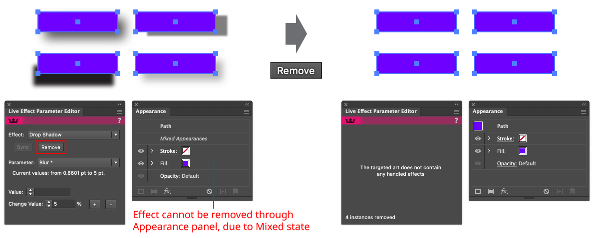
Live Effect Parameter Editor Removing Effects
6. Copy Menu
Specifies the copy of the live effect to operate on when some or all of the targeted art objects contain more than one copy of the effect (numbered from the top down as they appear in the Appearance panel). The Sync button, Remove button, and parameter controls only affect that copy.
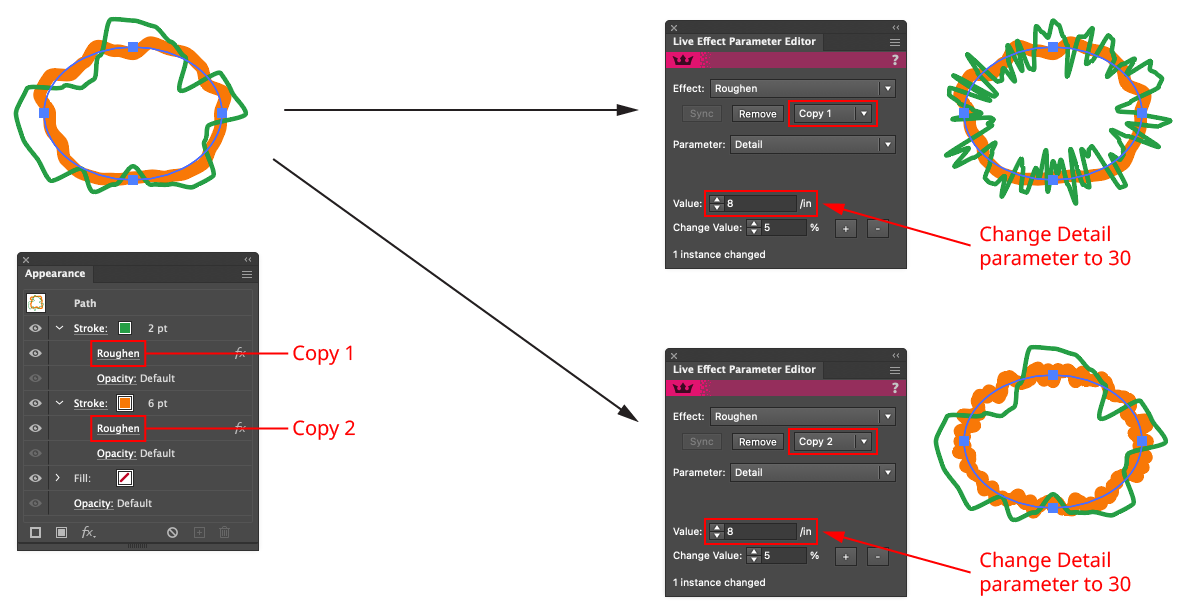
Live Effect Parameter Editor Copy Menu
If the Copy menu is set to a value which does not exist in some targeted art objects (for example, if set to Copy 3 but some targeted objects only have one or two copies), then those objects will have their last copy of the effect removed or modified instead. A warning icon will be displayed to indicate this.
7. Parameter Menu
Chooses the parameter to edit for the currently selected live effect. Most effects can have all of their parameters edited, but a few have unsupported parameters, such as Stipple’s Scale Dots by Tone curve, and these will therefore not appear in the menu. Parameters are listed in roughly the natural, top-to-bottom reading order in which they would appear in the effect’s parameters dialog. Their names may be somewhat altered from the native dialog, due to clarity and length considerations. An asterisk (“*”) following the parameter name indicates that the parameter has multiple (mixed) values.
8. Current Range
If a parameter has multiple (mixed) values in the targeted art, its current range of values will be displayed here. For example, a length-value parameter might have its range reported as “from 3 pt to 8 pt”. A parameter with discrete types might have its range reported as “‘Circle’, ‘Square’, and ‘Star’”.
9. Value Controls
Allows the parameter to be edited, using a control suitable for the parameter type:
Parameters with real or integer values use a standard value input box:

Live Effect Parameter Editor Real and Integer Value Controls
Parameters with only two distinct values (including those “on-or-off” types typically controlled by a checkbox) use radio buttons:

Live Effect Parameter Editor Radio Controls
Parameters with multiple but distinct values use a dropdown menu:

Live Effect Parameter Editor Dropdown Menu Controls
Parameters specifying an orientation use a standard nine-block control:

Live Effect Parameter Editor Nine Block Controls
Parameters specifying a color use a color chip, which can be clicked to bring up the standard Color Picker:

Live Effect Parameter Editor Color Chip Controls
10. Change Value Controls
Available for parameters with real and integer values, the change value controls allow the parameter’s value(s) to be scaled either up or down by the specified amount (while staying within its allowable range). This is possible whether the parameter is in a mixed state or not. For example, if two objects with an Offset Path live effect are targeted — one with an offset of 10 pt and the other with an offset of 15 pt — and the Change value is set to 10%, then clicking the “+” button would change the offsets to 11 pt and 16.5 pt respectively.
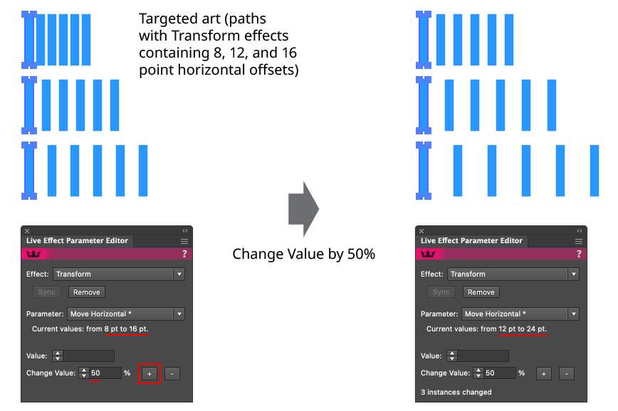
Live Effect Parameter Editor Change Value Example
Illustrator Location:
Illustrator Main Menu > Effect > VectorScribe > AG Corners...
AG Corners is an Astute Graphics live effect for paths that improves the native “Round Corners” effect, by allowing for the rounding of points adjacent to curved segments without distorting them, by implementing the different corner types and methods found in the Dynamic Corners panel, and by allowing different corner types on the outside and the inside corners. AG Corners is part of the VectorScribe plugin.
As with most live effects, AG Corners appears in the main menu, under Effect > VectorScribe. It can also be applied directly from the Appearance panel using the “Add New Effect” button at the bottom of the panel.
AG Corners Parameters Dialog
After applying the live effect using the menu item (or when clicking on the existing effect in the Appearance panel to edit it), the parameters dialog will appear:
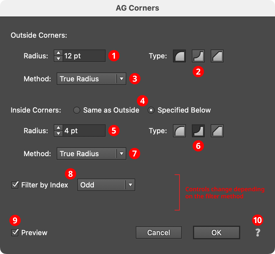
AG Corners Parameters Dialog
1. Outside Corners Radius
The radius of each outside corner. “Outside” is only defined for closed, non-intersecting paths, and means a corner which has its concave side on the interior of the path. If a corner cannot accommodate the specified radius, its radius will be made as large as possible. Corners cannot extend past the next anchor point along the path in either direction, so sometimes placing a Smart Remove Points live effect before the AG Corners effect can fix issues where additional anchor points have been inadvertently added by effects such as AG Offset.
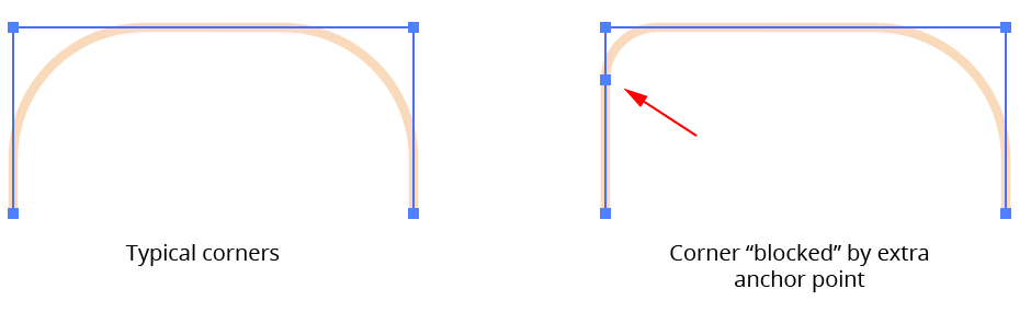
AG Corners Blocked Corners Example
2. Outside Corners Type
Specifies the type of outside corners, either Regular (curve facing outwards), Negative (curve facing inwards), or Chamfered (a straight line cutting across the corner).
3. Outside Corners Method
For curved corners (Regular and Negative), specifies the method used to draw the corner.
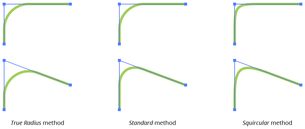
AG Corners Method Example
True Radius method corners are created with one or two circular segments and maintain a constant radius as closely as is possible using the cubic bezier curves with which all Illustrator paths are constructed.
Standard method corners are the type that the native “Round Corners” live effect creates. When placed on a right angle, they are identical to True Radius corners, but at other angles they are of non-constant radii, the values of which vary substantially from the nominal radius value. They are useful for certain shapes which tend to look incorrect with True Radius corners:
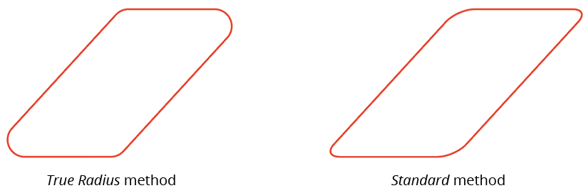
AG Corners Standard corner example
Squircular method corners approximate the “Squircle” curve popularized by Apple. A squircle is a blend between a square and a circle. These non-constant-radius corners feature a smoother transition between the curved section and the straight section of path, and are most useful on the right angles of squares and rectangles. A Squircular corner of the same nominal radius as a True Radius corner will look smaller due to its changing curvature.
4. Inside Corners Treatment
Specifies whether inside corners use the same parameters as outside corners or whether they have their own, independent parameters. In the latter case, the same three parameters are available as with outside corners. “Inside” is only defined for closed, non-intersecting paths, and means a corner which has its concave side on the exterior of the path.
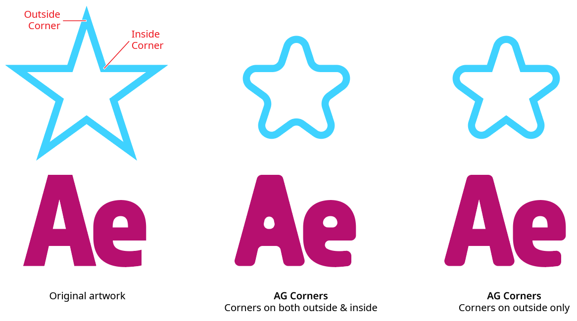
AG Corners Inside and Outside Corner Example
5. Inside Corners Radius
Available when inside corners are treated independently. It is the same as Outside Corners Radius, but for inside corners only.
6. Inside Corners Type
Available when inside corners are treated independently. It is the same as Outside Corners Type, but for inside corners only.
7. Inside Corners Method
Available when inside corners are treated independently. It is the same as Outside Corners Method, but for inside corners only.
8. Filter By Index
When enabled, each eligible anchor point’s index along the path is used to determine whether it should have a corner added, using one of seven different methods. The index is simply an integer sequentially assigned to each eligible anchor point in the original path, starting with zero (points that can never hold a corner, such as endpoints of open paths and smooth points, are not “eligible” and are therefore not included in the numbering). The available By Index methods are as follows:
a. First: Only the first n eligible points are affected, where n is the specified value.

AG Corners Filter by Index First Controls
b. Last: Only the last n eligible points are affected, where n is the specified value.

AG Corners Filter by Index Last Controls

AG Corners Filter by Index First - Last
c. First or Last: Only the first and last eligible points are affected.
d. Odd: Only eligible points with an odd index (1, 3, 5, 7...) are affected.
e. Even: Only eligible points with an even index (0, 2, 4, 6...) are affected.

AG Corners Filter by Index Odd
f. Pattern: Creates a repeating pattern of matching indices based on the three pattern parameters.

AG Corners Filter by Index Pattern Controls
Initial Skip specifies the number of indices to skip over at the start (eligible points with these indices will not be affected). Then, Match specifies the number of indices that will match and therefore be affected. Finally, Skip specifies the number of indices to skip over following the matching indices. When the total of the values in the three parameters is less than the number of eligible points, the pattern repeats, using the Match and Skip values in alternation.

AG Corners Filter by Index Even - Pattern
g. Randomly: Each eligible point has the specified random chance (from 0% to 100%) of having a corner added. Each random seed number leads to a different sequence of random values. Clicking the Seed button picks a new seed, thereby changing the look of the artwork. To view or specify the seed number directly,
Option/Alt-clickthe button. This lets you recreate a previously-generated look.

AG Corners Filter by Index Randomly Controls

AG Corners Filter by Index Randomly
9. Preview
As with all live effects, when enabled, changing a parameter will immediately update the artwork while the dialog is still open.
10. Help Button
Opens the help documentation in the Astute Manager. If this does not automatically appear, please ensure your Astute Manager is running first.
Illustrator Location:
Illustrator Main Menu > Effect > AG Utilities > ...
Add Points is an Astute Graphics live effect for paths that adds anchor points to paths, similar to the functionality of the “Add Points” function of the PathScribe panel. By itself, adding points is not particularly useful, as the look of the art won’t change; the real power comes by stacking the live effect with other live effects that operate on or depend on anchor point placement.
As with most live effects, Add Points appears in the main menu, under Effect > AG Utilities. It can also be applied directly from the Appearance panel using the “Add New Effect” button at the bottom of the panel.
Add Points Parameters Dialog
After applying the live effect using the menu item (or when clicking on the existing effect in the Appearance panel to edit it), the parameters dialog will appear:
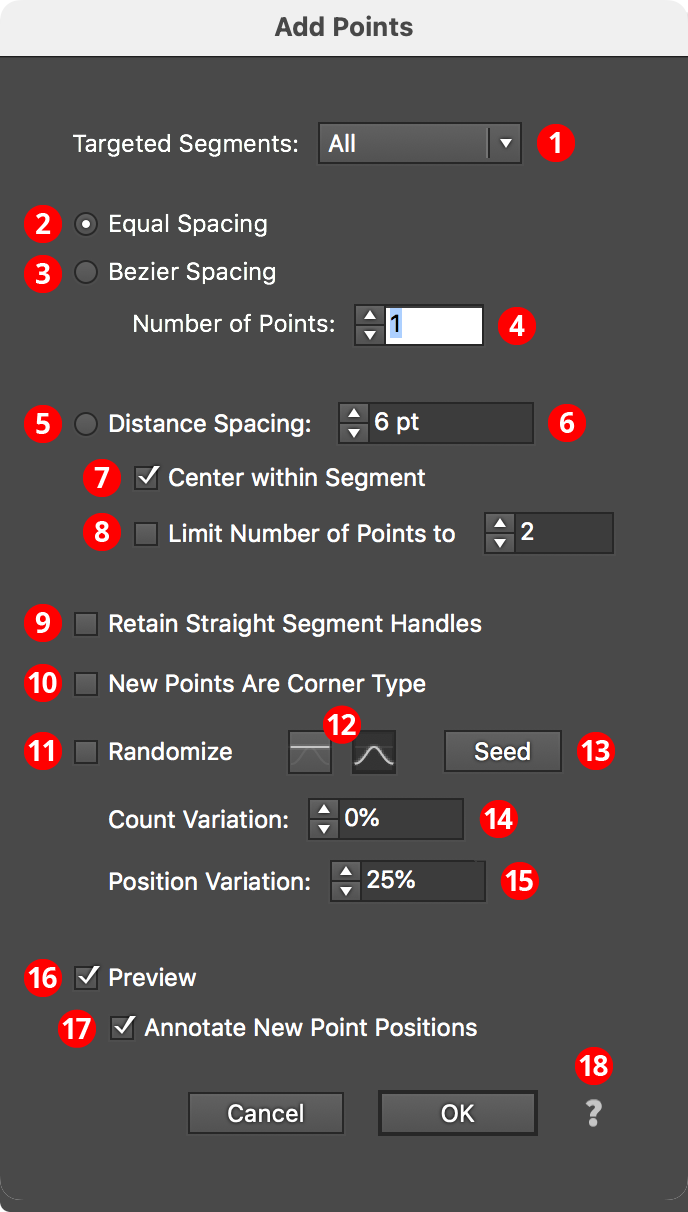
Add Points Parameters Dialog
1. Targeted Segments
By default, all segments in the path have points added to them, but this can be changed to First, Last, Even Only, Odd Only, Curved Only, or Straight Only segments. Even and odd refer to the index number of the segment, which starts at zero for the first segment in the path.
2. Equal Spacing Mode
In this mode, points are added such that the space between them (as measured along the path) is equal.
3. Bezier Spacing Mode
In this mode, points are added such that the cubic bezier t parameter is equally spaced. Generally, this adds more points to areas along the segment which are more tightly curved.
4. Number of Points
For Equal Spacing and Bezier Spacing modes, specifies the number of points to add along each segment.
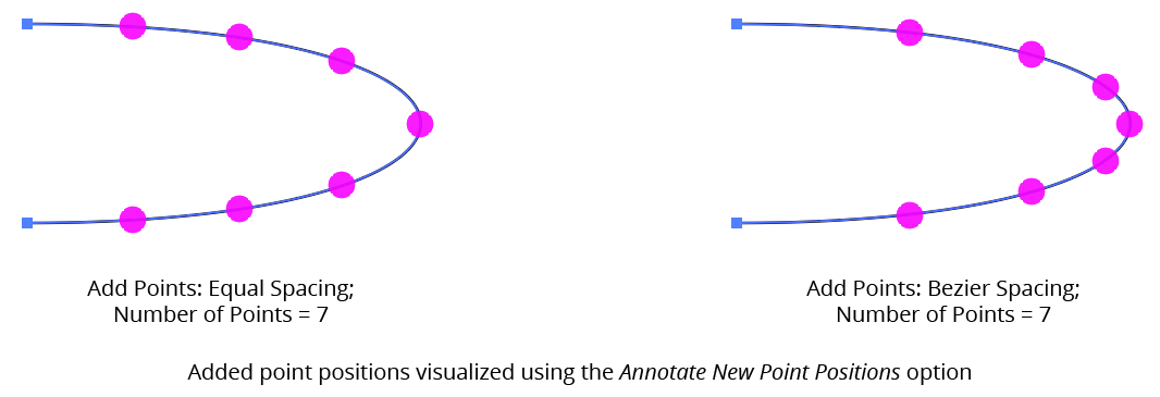
AG Utilities Live Effects - Add Points Equal or Bezier Spacing
5. Distance Spacing Mode
In this mode, points are added equally spaced along the path with the distance specified, adding as many as will fit along the segment unless Limit Number of Points is also enabled.
6. Distance Value
The distance between the added points when using Distance Spacing mode. If the distance value is greater than the segment’s length, no points will be added to the segment.
7. Center Within Segment
In Distance Spacing mode, causes the added points to be centered within the segment, so the distances from the segment’s ends to the first or last added point will be equal (but may not match the specified distance).
8. Limit Number of Points
In Distance Spacing mode, specifies the maximum number of points to add along each segment.
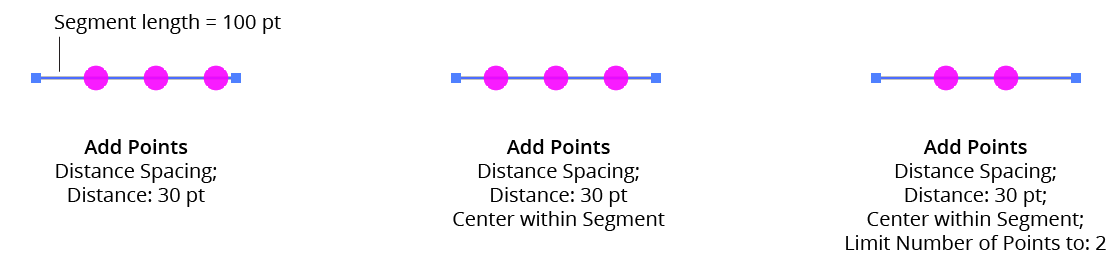
AG Utilities Live Effects - Add Points Distance Spacing
9. Retain Straight Segment Handles
Normally, when anchor points are added to a handleless straight segment, the new points have their handles removed. However, enabling this setting causes the handles to be retained, which can be useful when the new anchor points are subsequently moved and a smooth curve is desired.
10. New Points Are Corner Type
Forces the added points to have corner type rather than smooth. This does not change any handles that the point might have, only the point type.
11. Randomize
Allows for random variation in the count and/or position of the new points.
12. Distribution Curves
Specifies either a linear distribution in random values (all values in the range are equally likely to be chosen) or a Gaussian distribution (central values in the range are more likely to be chosen).
13. Seed
Each random seed number leads to a different sequence of random values. Clicking the button picks a new seed, thereby changing the look of the artwork. To view or specify the seed number directly, Option/Alt-click the button. This lets you recreate a previously-generated look.
14. Count Variation
Specifies the random variation in the added point count (valid for Equal Spacing and Bezier Spacing modes only). For example, if the count is set to 20, then a variation value of 25% would produce count values that vary by as much as 20 × 25% = 5, that is, between 16 and 20; a variation value of 100% would produce count values between 1 and 20.
15. Position Variation
Specifies the random variation in the final positions of the added points.
16. Preview
As with all live effects, when enabled, changing a parameter will immediately update the artwork while the dialog is still open.
17. Annotate New Point Positions
When enabled, the positions of the added points will be temporarily displayed using magenta dot annotations, which is useful if subsequent live effects have not been added to the artwork yet, because by itself, Add Points will produce no visual change to the art.
18. Help Button
Opens the help documentation in the Astute Manager. If this does not automatically appear, please ensure your Astute Manager is running first.
Illustrator Location:
AG Array is an Astute Graphics live effect for creating arrays, or grids, of artwork. It includes multiple methods of specifying the horizontal and vertical sizes, and can stagger the items as well as switch their stacking order.
As with most live effects, AG Array appears in the main menu, under Effect > AG Utilities. It can also be applied directly from the Appearance panel using the “Add New Effect” button at the bottom of the panel.
AG Array Parameters Dialog
After applying the live effect using the menu item (or when clicking on the existing effect in the Appearance panel to edit it), the parameters dialog will appear:
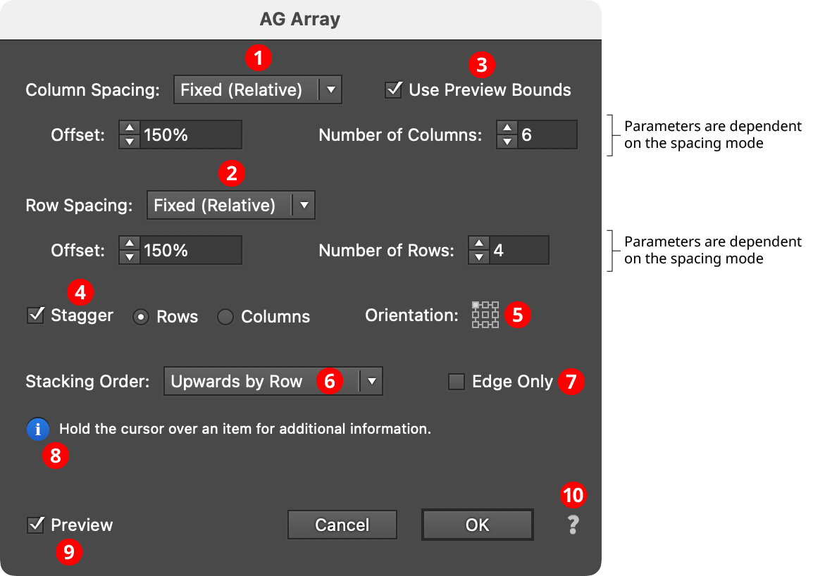
AG Array Parameters Dialog
1. Column Spacing Mode
The column spacing of the array can be specified in one of four ways:
a. Fixed (Absolute): The horizontal offset between columns is specified as an absolute value (for example, 72 pt). If this value is smaller than the width of the art object, the columns will overlap. The number of columns is also specified, from 1 to 1000.
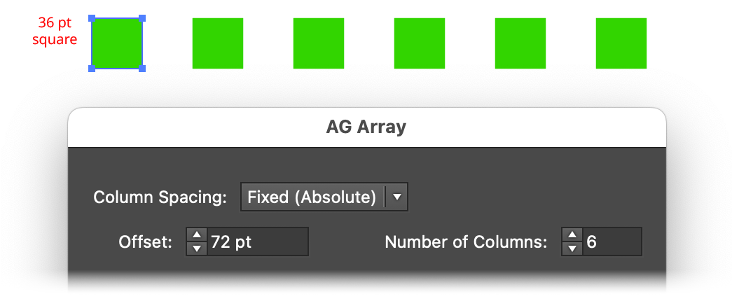
AG Array Spacing - Fixed (Absolute) Mode
b. Fixed (Relative): The offset between columns is specified as a percentage value relative to the width of the bounding box of the art (for example, 150%). If this value is less than 100%, the columns will overlap. As with Fixed (Absolute), the number of columns is also specified, from 1 to 1000.
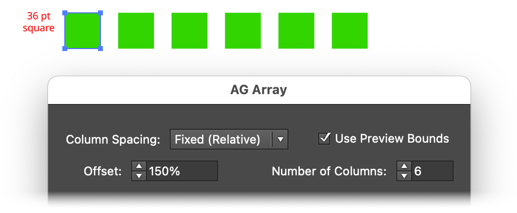
AG Array Spacing - Fixed (Relative) Mode
c. Total Dimension: The overall width of the array is specified. If this value is equal to or smaller than the width of the art object, then all of the columns will be stacked atop each other. Otherwise AG Array adjusts the offset so the specified number of columns is evenly spaced across the width.
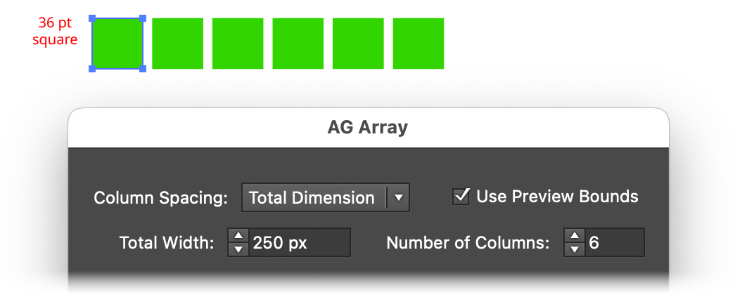
AG Array Spacing - Total Dimension Mode
d. Fill: As with Total Dimension mode, the final width of the array is specified. AG Array then creates as many columns as will fit in this width while keeping the gutter between columns equal to or greater than the Minimum Gutter value.
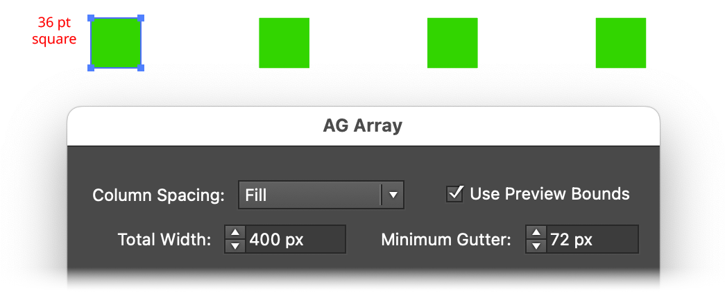
AG Array Spacing - Fill Mode
2. Row Spacing Mode
The row spacing of the array can be specified in one of four ways:
a. Fixed (Absolute): The vertical offset between rows is specified as an absolute value (for example, 72 pt). If this value is smaller than the height of the art object, the rows will overlap. The number of rows is also specified, from 1 to 1000.
b. Fixed (Relative): The offset between rows is specified as a percentage value relative to the height of the bounding box of the art (for example, 150%). If this value is less than 100%, the rows will overlap. As with Fixed (Absolute), the number of rows is also specified, from 1 to 1000.
c. Total Dimension: The overall height of the array is specified. If this value is equal to or smaller than the height of the art object, then all of the rows will be stacked atop each other. Otherwise AG Array adjusts the offset so the specified number of rows is evenly spaced across the height.
d. Fill: As with Total Dimension mode, the final height of the array is specified. AG Array then creates as many rows as will fit in this height while keeping the gutter between rows equal to or greater than the Minimum Gutter value.
3. Use Preview Bounds
Overrides the general preference of the same name. When enabled, the strokes and live effects of the artwork are included in its bounding box, which affects column or row positioning unless the spacing mode is set to Fixed (Absolute).
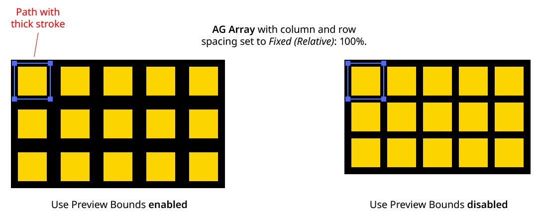
AG Array Use Preview Bounds
4. Stagger
When enabled, alternate rows (or columns) are shortened by one item and shifted so their items fall halfway between those of the previous row or column.
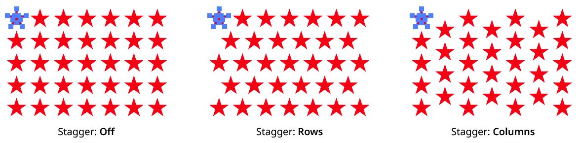
AG Array Stagger
5. Orientation
Specifies the orientation of the entire array in relation to the bounding box of the original art. The default is to have the upper left corner of the array in the same location as the upper left corner of the original art.
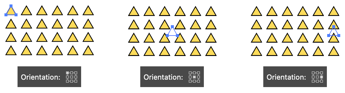
AG Array Orientation
6. Stacking Order
Specifies how the items in the array are stacked: Upwards by Row, Upwards by Column, Downwards by Row, or Downwards by Column, where row items are created from left to right and column items are created from top to bottom.
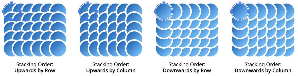
AG Array Stacking Order
7. Edge Only
When enabled, only the first and last columns and rows of the array will be populated.
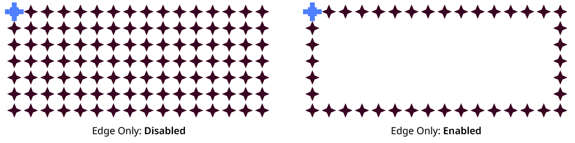
AG Array Edge Only
8. Informational area
Shows a brief description of each control when the cursor is being hovered over it.
9. Preview
As with all live effects, when enabled, changing a parameter will immediately update the artwork while the dialog is still open.
10. Help Button
Opens the help documentation in the Astute Manager. If this does not automatically appear, please ensure your Astute Manager is running first.
Illustrator Location:
AG Shear is an Astute Graphics live effect that adds the ability to shear art objects, including live text, non-destructively — without resorting to hard-to-edit, multiple-stacked native Transform effects.
As with most live effects, AG Shear appears in the main menu, under Effect > AG Utilities. It can also be applied directly from the Appearance panel using the “Add New Effect” button at the bottom of the panel.
AG Shear Parameters Dialog
After applying the live effect using the menu item (or when clicking on the existing effect in the Appearance panel to edit it), the parameters dialog will appear:
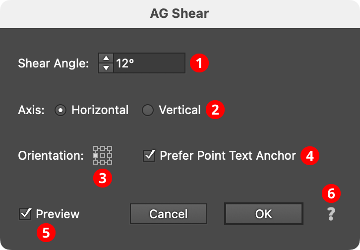
AG Shear Parameters Dialog
1. Shear Angle
The angle of the shear, from –85° to 85°. As with the native Shear tool, positive shear angles slant the artwork to the right (when the axis is set to horizontal) or downwards (when the axis is set to vertical).
2. Axis
The axis along which to shear, either Horizontal or Vertical. Axes of an arbitrary angle, which are rarely used, are not supported.
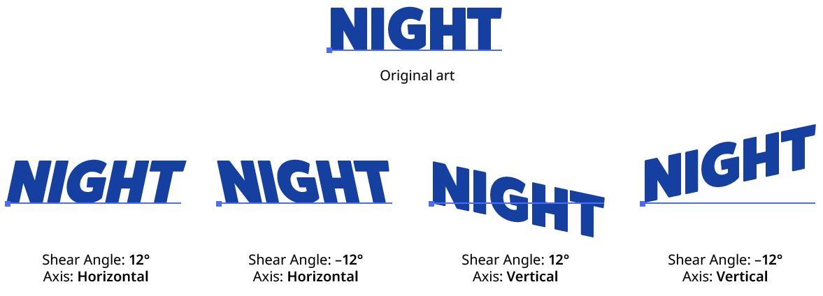
AG Shear Examples
3. Orientation
The position of the shear’s transformation point in relation to the artwork’s bounding box.
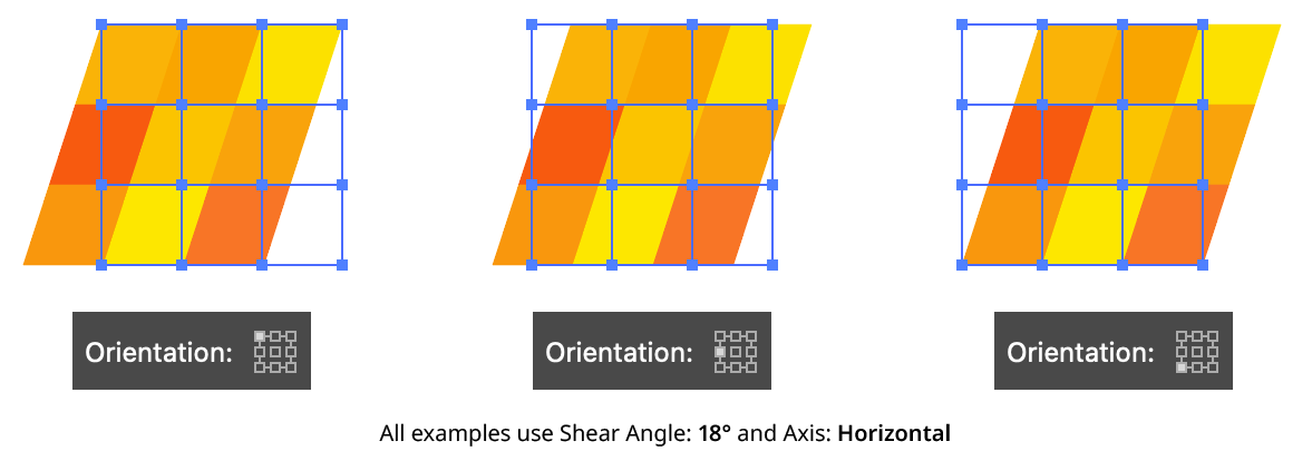
AG Shear Orientation
4. Prefer Anchor Point Text
When enabled, and the art object is a single point text object, then the shear’s transformation point will always be placed at the anchor point of the text object, regardless of the Orientation setting. This ensures that the baseline of the text passes through the anchor point of the text, as normal.
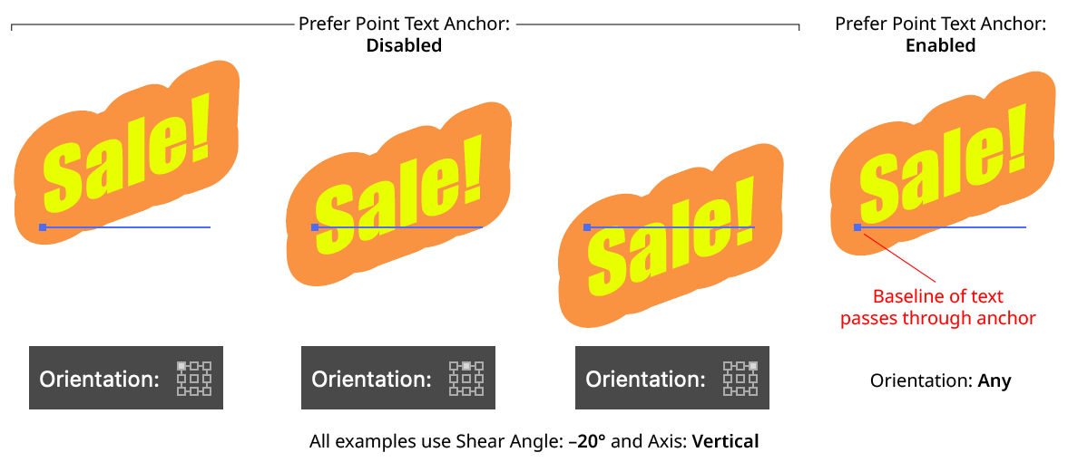
AG Shear Prefer Point Text Anchor
5. Preview
As with all live effects, when enabled, changing a parameter will immediately update the artwork while the dialog is still open.
6. Help Button
Opens the help documentation in the Astute Manager. If this does not automatically appear, please ensure your Astute Manager is running first.
Illustrator Location:
Illustrator Main Menu > Effect > AG Utilities > AG Transform
AG Transform is a powerful Astute Graphics live effect that greatly expands upon the native Transform effect by adding features such as the ability to affect different grouping levels of the art, the option to move by distance and angle instead of simply by X- and Y-coordinates, sequences with separate parameters, additional options for specifying the centers of scaling and rotation, the ability to change the stacking order, filtering for only affecting a subset of multiple objects, and more.
As with most live effects, AG Transform appears in the main menu, under Effect > AG Utilities. It can also be applied directly from the Appearance panel using the “Add New Effect” button at the bottom of the panel.
AG Transform Parameters Dialog
After applying the live effect using the menu item (or when clicking on the existing effect in the Appearance panel to edit it), the parameters dialog will appear. The dialog is large, and is described by section:
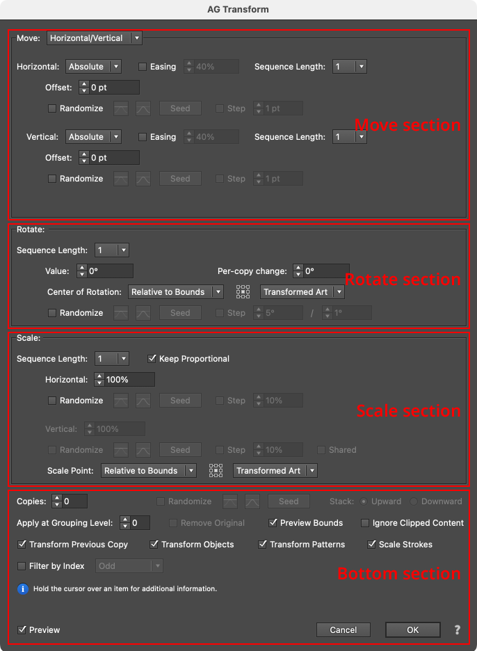
AG Transform Parameters Dialog Sections
Although the Move, Rotate and Scale sections are stacked in that order on the panel, the operations are actually performed in the reverse order. In other words, to transform the art, it is first scaled, then rotated, and finally moved. This is consistent with the native Transform effect’s order of operations.
Illustrator Location:
Moving (offsetting) can be done in two main modes: Horizontal/Vertical (as with the native Transform, in which the offset is specified by its horizontal and vertical components) or Distance/Angle, in which the offset is specified by its distance and angle components. The main mode is controlled by a dropdown menu at the top of the Move section. In Horizontal/Vertical mode, the move section of the dialog has the following controls:
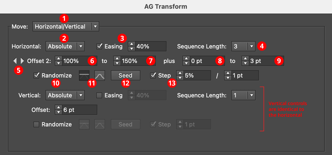
AG Transform Parameters Dialog: Move Section (Horizontal, Vertical)
1. Main Mode
The dropdown menu allows the choice between Horizontal/Vertical mode and Distance/Angle mode.
2. Horizontal/Vertical Submode
In Horizontal/Vertical mode, the dropdown menu allows the choice between Absolute or Relative submodes for both the horizontal and vertical components of the offset. In Absolute submode, each offset component is specified using an absolute value, such as 12 pt. In Relative submode, each offset component is specified using a percentage of the width (or height, for the vertical component) of the art’s bounding box, plus an optional non-relative value. Thus, when the submode is set to Relative and the offset is set to 100%, the “plus” value controls the gap between objects when multiple copies are made:
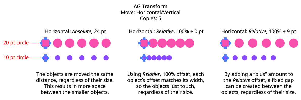
AG Transform Move Absolute Vs. Relative
3. Horizontal/Vertical Easing
Easing controls the final spacing (either in the horizontal or vertical direction) of all of the transformed copies. When enabled, the easing value (from 1% to 99%) specifies where the middle copy should be placed (as a percentage of the distance from the original to the last copy). It therefore determines whether the copies increase their spacing as they get further away from the original (for values less than 50%), or decrease their spacing (for values more than 50%).
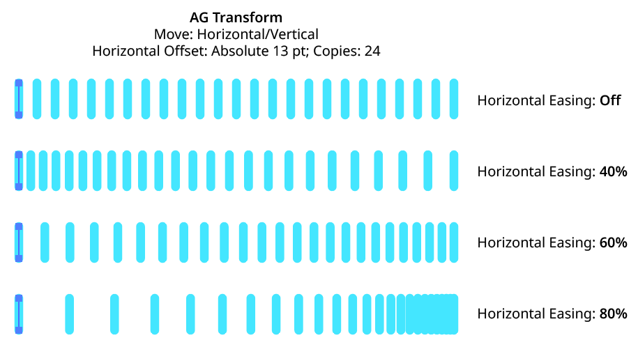
AG Transform Easing Examples 1
Easing can be used with both sequences and randomization. If the offsetting causes the copies to be created both to the left and right of the original, then the easing is done separately for each side.
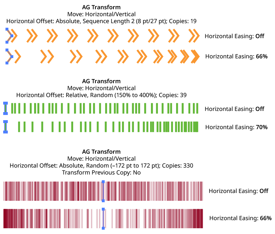
AG Transform Easing Examples 2
Using a different easing value for the horizontal and vertical components of the offset causes the trail of copies to move in a curve:
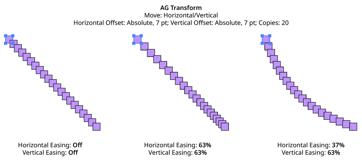
AG Transform Easing Examples 3
4. Horizontal/Vertical Sequence Length
By default (and ignoring randomization), each copy receives the same offset (as with the native Transform effect). However, AG Transform offers sequences, which allow up to 8 different offsets. The horizontal component of the offset can have a different sequence length from the vertical. If the number of copies exceeds the length of the sequence, the values simply repeat in a cycle. Each member of a sequence shares the same randomization parameters.
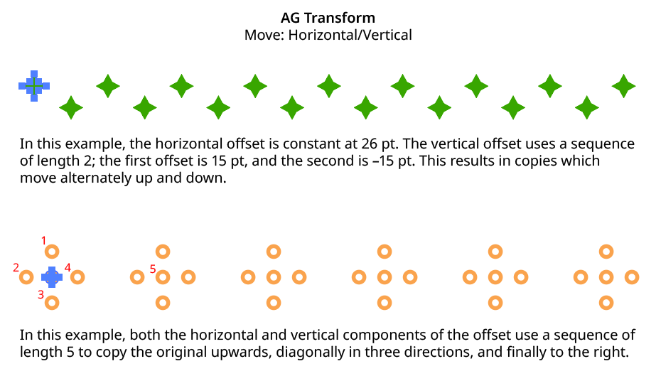
AG Transform Horizontal Vertical Sequence Examples
5. Previous/Next Offset Buttons
Available when the sequence length is set to a value other than 1. Clicking either button will move between the sequence’s offsets, allowing any of them to be edited.
6. Offset/Minimum Offset
The horizontal (or vertical) offset for the current sequence index. In Absolute submode, this is an absolute value like 12 pt. In Relative submode, this is a percentage of the width (or height) of the bounding box of the art. When randomization is enabled, this value specifies the minimum offset that may be randomly produced.
7. Maximum Offset
Available when randomization is enabled; it specifies the maximum horizontal (or vertical) offset that may be randomly produced for the current sequence index.
8. “Plus” Offset/Minimum “Plus” Offset
Available when in Relative submode; it specifies an additional non-relative offset that is added to the relative offset for the current sequence index (and may be negative). When used with a relative offset of 100%, for example, this could be used to create fixed gaps of a specific size between copies, regardless of the size of the original art. When randomization is enabled, this value specifies the minimum “plus” offset that may be randomly produced.
9. Maximum “Plus” Offset
Available when in Relative submode and randomization is enabled; it specifies the maximum horizontal (or vertical) “plus” offset that may be randomly produced for the current sequence index.
10. Horizontal/Vertical Randomize
When randomization is enabled, the offset (or offsets, if using a sequence) are not fixed for each copy, but are chosen randomly between the specified minimum and maximum values. The distribution of those values (linearly or in a Gaussian manner) can be specified, as well as the random seed. All sequence indices share the same randomization parameters.
11. Distribution Curves
Specifies either a linear distribution in random values (all values in the range are equally likely to be chosen) or a Gaussian distribution (central values in the range are more likely to be chosen, also known as a “bell curve”).
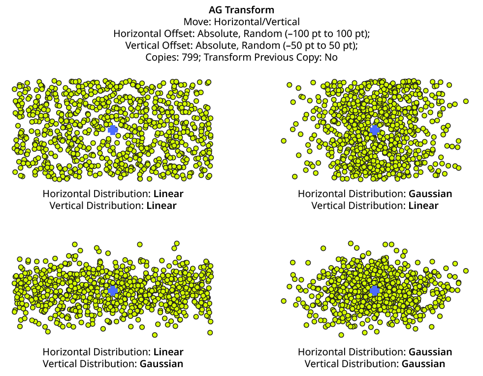
AG Transform Linear Vs. Gaussian Distribution
12. Seed
Each random seed number leads to a different sequence of random values. Clicking the button picks a new seed, thereby changing the look of the artwork. To view or specify the seed number directly, Option/Alt-click the button. This lets you recreate a previously-generated look. The horizontal and vertical components of the offset have independent seeds.
13. Step
Constrains each final offset value (after randomization) to multiples of the specified step value while still remaining in the original range (when possible). For example, if an absolute offset is set to a minimum of 12 pt and a maximum of 24 pt, then normally any value between those amounts might be produced — say, 17.448 pt. But enabling Step with a value of 5 pt would result in only values of 15 pt and 20 pt.
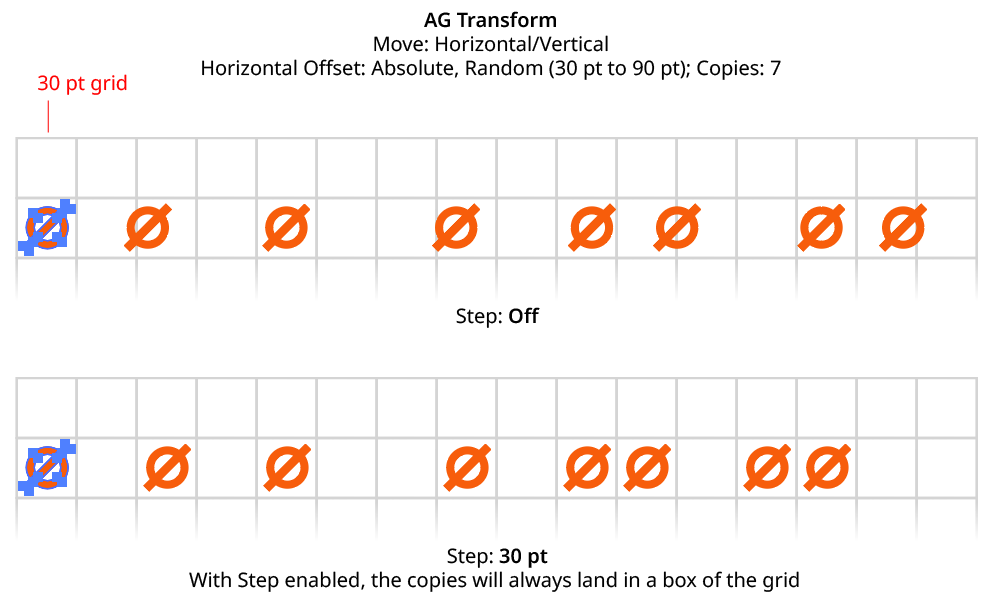
AG Transform Horizontal Offset with Step
When using Step with Relative offsets, two step values are available. The first value is the step value for the relative amount (a percentage), and the second is the step value for the absolute “plus” offset.
Illustrator Location:
In Distance/Angle mode, the Move section of the dialog has the following controls:
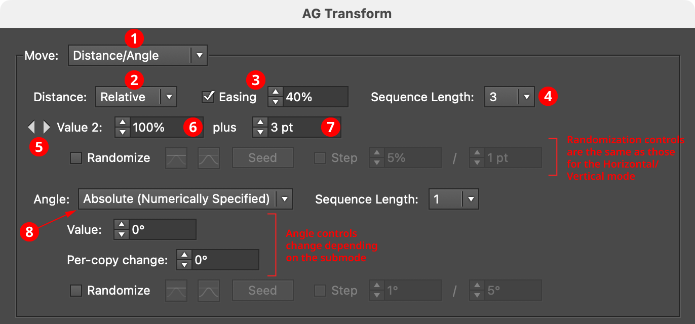
AG Transform Parameters Dialog, Move Section (Distance Angle)
1. Main Mode
The dropdown menu allows the choice between Distance/Angle mode and Horizontal/Vertical mode.
2. Absolute/Relative Submode
The dropdown menu allows the choice between Absolute or Relative submodes for the distance component of the offset. In Absolute submode, the offset is specified using an absolute value, such as 12 pt. In Relative submode, the value is specified using a percentage of the width of its bounding box, plus an additional non-relative value.
3. Distance Easing
Easing controls the final spacing of all of the transformed copies based on their distance from the original object. When enabled, the easing value (from 1% to 99%) specifies where the middle copy should be placed (as a percentage of the distance from the original to the last copy). It therefore determines whether the copies increase their spacing as they get further away from the original (for values less than 50%), or decrease their spacing (for values more than 50%).
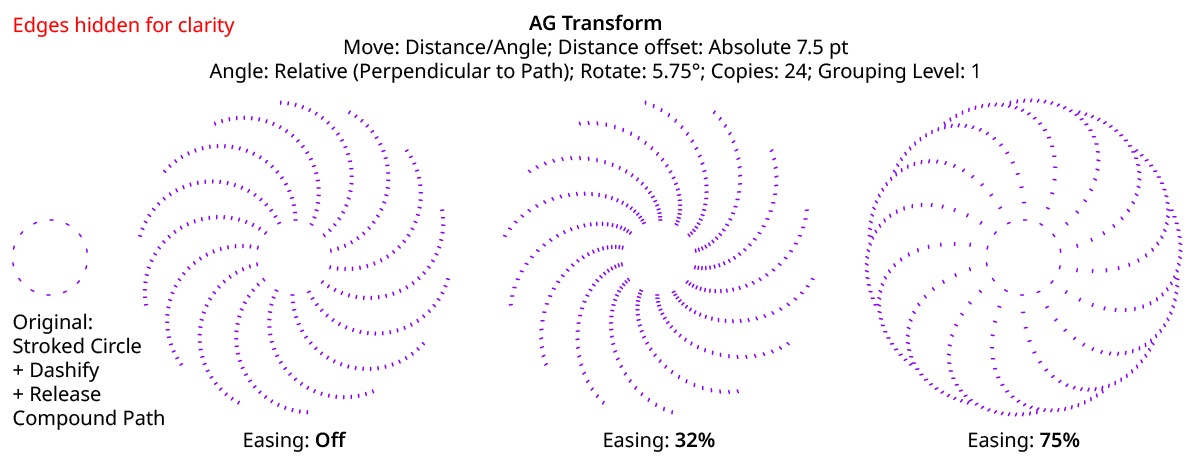
AG Transform Distance Easing
Distance easing can be used with both sequences and randomization.
4. Distance Sequence Length
See Horizontal/Vertical Sequence Length.
5. Previous/Next Value Buttons
Available when the sequence length is set to a value other than 1. Clicking either button will move between the sequence’s values, allowing any of them to be edited.
6. Offset/Minimum Value
The distance value for the current sequence index. In Absolute submode, this is an absolute value like 12 pt. In Relative submode, this is a percentage of the width of the bounding box of the original art. When randomization is enabled, this value specifies the minimum value that may be randomly produced.
7. Maximum Value
Available when randomization is enabled; it specifies the maximum value that may be randomly produced for the current sequence index.
8. Angle Submode
The dropdown menu allows the choice between Absolute (Numerically Specified), Relative (Start Point/End Point), or Relative (Perpendicular to Path) submodes for the angle component of the offset.
Absolute (Numerically Specified) submode: the angle is specified using an absolute value, such as 45°. In this submode, the angle controls are as follows:
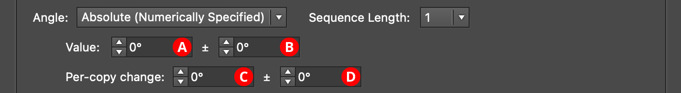
AG Transform Parameters Dialog, Angle Absolute Submode
A. Value/Base Value: The angle component of the offset for the current sequence index. When randomization is enabled, this value specifies the base angle to which a random amount is added or subtracted.
B. Base Value Variation: Available when randomization is enabled; it is the maximum angular amount which is added to or subtracted from the base value to get the random value. For example, if the base value is set to 45°, and the random variation is set to 10°, then angles from 35° to 55° may be produced.
C. Per-copy Change Value: The angular amount to add to the base value for each new copy. For example, if the base value is set to 20°, and the per-copy change is set to 3°, then the first copy will be offset at an angle of 20°, the second at 23°, the third at 26°, and so on. This has the effect of making the copies lie along a circular arc.
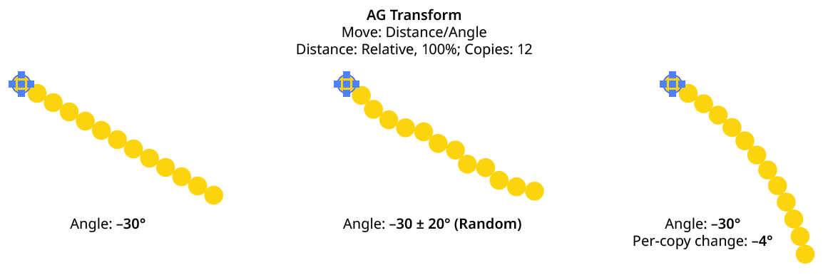
AG Transform Angle Absolute Examples
D. Per-copy Change Value Variation: Available when randomization is enabled; it is the maximum angular amount which is added to or subtracted from the per-copy change value to get the random value.
Relative (Start Point/End Point) submode: the offset angle is that of an imaginary line that starts at one point and ends at another. These points are not necessarily path anchor points, but may be specified using one of five different methods. Relative submodes are most useful when there are multiple objects in the selection that are being transformed. In this submode, the angle controls are as follows:
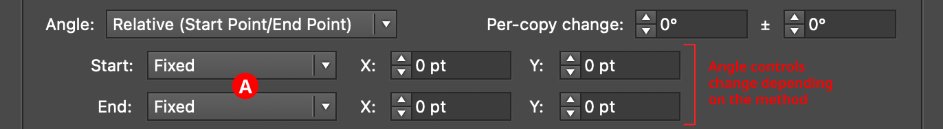
AG Transform Parameters Dialog, Angle Relative (Start End) Submode
A. Start/End Method: The dropdown menu for both the start and end points allows the choice between five different methods of specifying each point: Fixed, Relative to Bounds, Anchor Point, Position Along Path, or Tagged Path.
Fixed: With this method, the point is simply specified by its coordinates.

AG Transform Start End Point Fixed Controls
There would be no good reason to use Fixed for both the start and end points, because this would only result in the equivalent of an absolute angle. However, if the start point, say, uses Fixed, and the end point uses a different method which specifies the point relative to the art, then the copies will appear to “expand” from a common origin:
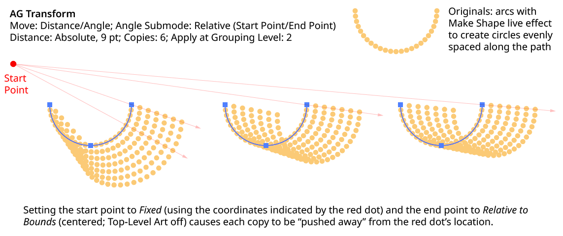
AG Transform Angle Fixed Start End
Relative to Bounds: With this method, the start or end point of the angle-determining line is located relative to the bounds of the original art, using the standard nine-box control. If the Apply at Grouping Level setting is set higher than zero, then the Top-Level Art checkbox becomes available. Turning off Top-Level Art means the bounds of each art object at the specified Grouping Level is used instead, which is usually desirable because each object will, in general, be offset at a different angle.

AG Transform Start End Point Relative to Bounds Controls
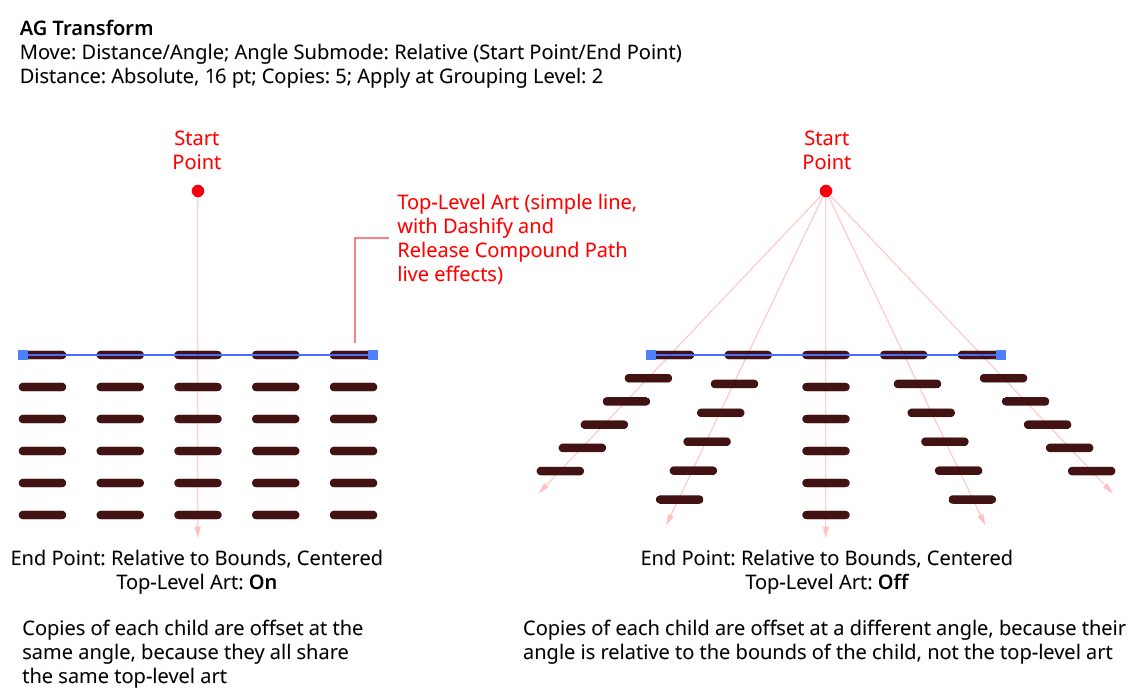
AG Transform Angle Top Level Art
Anchor Point: With this method, the start or end point of the angle-determining line is located at an anchor point of the art object at the current Grouping Level, using the specified index (starting at zero). If the specified index is equal to or greater than the number of points in the path, then the last point on the path is used. If the art object is not a path or does not contain a path, the Relative to Bounds method is used instead.

AG Transform Start End Point Anchor Point Controls
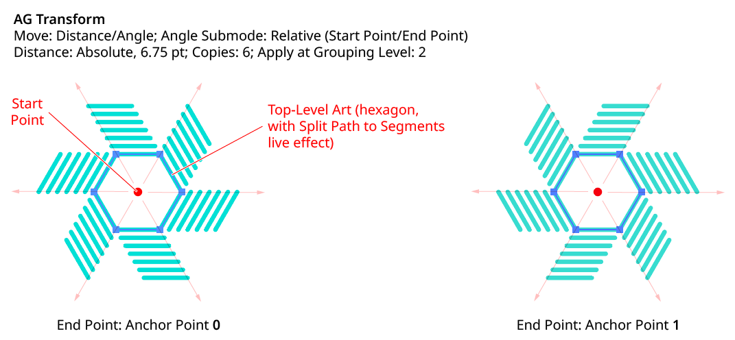
AG Transform Angle Anchor Point
Position Along Path: With this method, the start or end point of the angle-determining line is located at the specified position (from 0% to 100%) along the path of the art object at the current Grouping Level. If the art object is not a path or does not contain a path, the Relative to Bounds method is used instead.

AG Transform Start End Point Position Along Path Controls
Tagged Path: With this method, the start or end point of the angle-determining line is located at the first anchor point of the path contained in the top-level group that has the note “AGTransformStartEndPath” (as entered on the native Attributes panel). It is customary to use a single-point path for this purpose, so the path won’t inadvertently be made visible. If no such path exists, AG Transform uses the first path it finds in the top-level art. If no paths at all exist, the Fixed location is used instead.

AG Transform Start End Point Tagged Path Controls
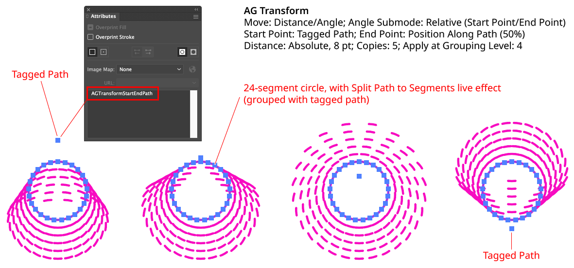
AG Transform Angle Tagged Path
Although similar to Fixed, the Tagged Path method allows the art to be moved around the artboard without changing its appearance, since the Tagged Path moves with it.
Relative (Perpendicular to Path) submode: the offset angle is perpendicular to the path of the art object at the current Grouping Level (if the art object is not a path or does not contain a path, an angle of 0° is used). The perpendicularity angle is calculated using a “right-hand” rule (i.e., to the right, relative to the direction of the path). Where the perpendicularity is calculated can be specified using either a fraction along the path, or a segment index plus t-value (the bezier-derived distance between the anchor point and the next anchor point). In this submode, the angle controls are as follows:
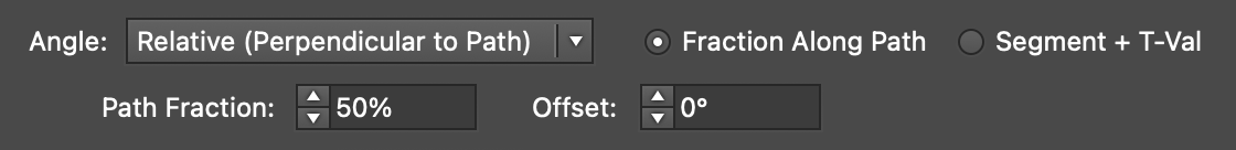
AG Transform Angle Perpendicular Path Fraction Controls
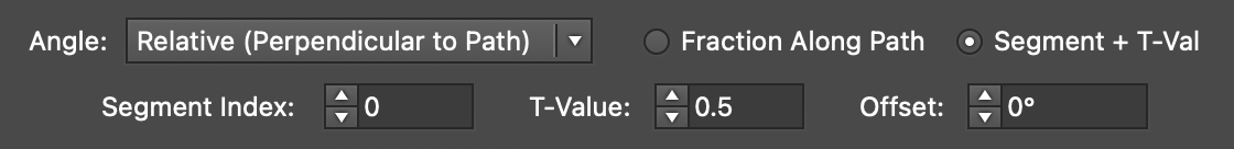
AG Transform Angle Perpendicular Index and T-Val Controls
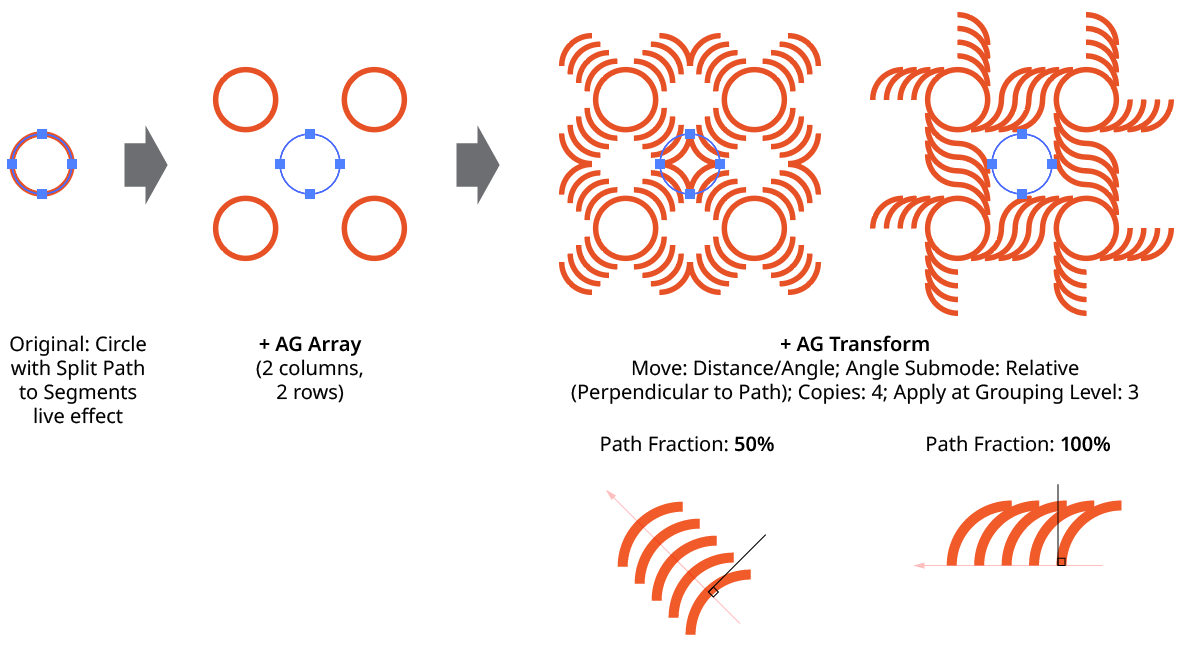
AG Transform Angle Perpendicular to Path
Using either method (Fraction Along Path or Segment + T-Val), an additional angular offset to the perpendicular angle may be added. Using a value of 180°, for example, can be useful if the path’s direction is the opposite of what is expected.
Although the offset angle is calculated once for the Relative (Start Point/End Point) submode and used for all subsequent copies, the angle for the Relative (Perpendicular to Path) submode is dynamically updated with each copy. Thus, if the art is rotated in addition to being offset, the offset angle will change to stay perpendicular to each copy.
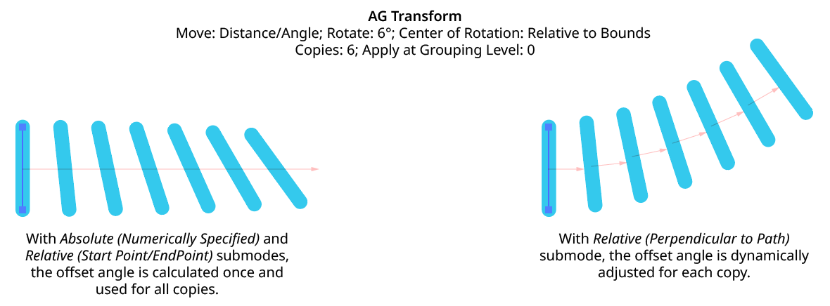
AG Transform Angle Perpendicular to Path with Rotation
Illustrator Location:
The Rotate section of the dialog has the following controls:
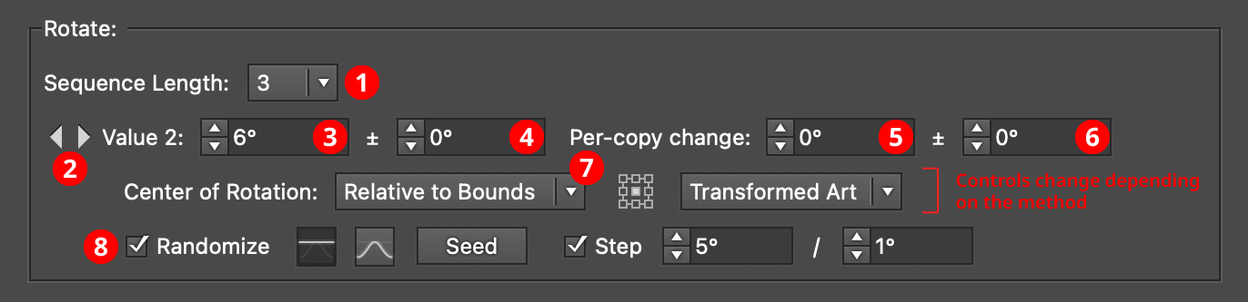
AG Transform Parameters Dialog, Rotate Section
1. Rotation Sequence Length
By default (and ignoring randomization), each copy receives the same rotation value (as with the native Transform effect). However, AG Transform offers sequences, which allow up to 8 different rotation values. If the number of copies exceeds the length of the sequence, the values simply repeat in a cycle. Each member of a sequence shares the same randomization parameters.
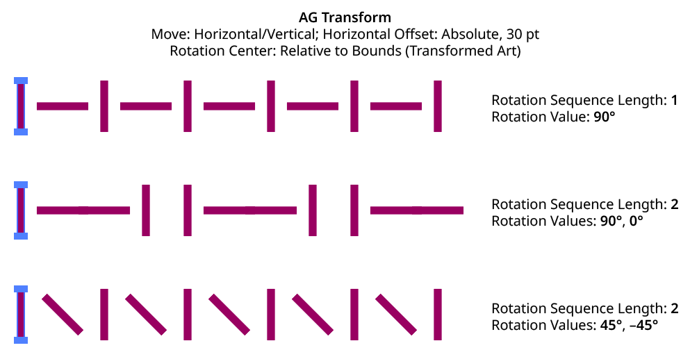
AG Transform Rotation Sequence Examples
2. Previous/Next Offset Buttons
Available when the sequence length is set to a value other than 1. Clicking either button will move between the sequence’s values, allowing any of them to be edited.
3. Value/Base Value
The angular value for the current sequence index. When randomization is enabled, this value specifies the base angle to which a random amount is added or subtracted.
4. Base Value Variation
Available when randomization is enabled; it is the maximum angular value which is added to or subtracted from the base value to get the random value. For example, if the base value is set to 45°, and the random variation is set to 10°, then angles from 35° to 55° may be produced.
5. Per-copy Change Value
The angular amount to add to the base value for each new copy. For example, if the base value is set to 20°, and the per-copy change is set to 3°, then the first copy will be rotated 20°, the second at 23°, the third at 26°, and so on.
6. Per-copy Change Value Variation
Available when randomization is enabled; it is the maximum angular amount which is added to or subtracted from the per-copy change value to get the random value.
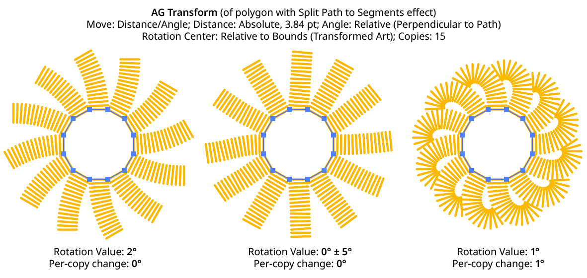
AG Transform Rotation Examples
7. Center of Rotation
The dropdown menu allows the choice between six different methods of specifying the center of rotation: Fixed, Relative to Bounds, Anchor Point, Position Along Path, Tagged Path, or Along Line.
Fixed: With this method, the center of rotation is simply specified by its coordinates.

AG Transform Center of Rotation Fixed Controls
This could be used to make multiple objects rotate around a common center, even if their position is subsequently adjusted:
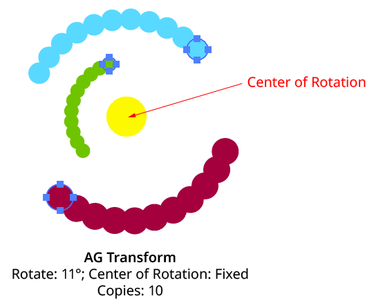
AG Transform Rotate Center Fixed
Relative to Bounds: This method (when used with Top-Level Art) is what the native Transform effect uses.

AG Transform Center of Rotation Relative to Bounds Controls
With this method, the center of rotation is located relative to the bounds of the specified art, using the standard nine-box control. The choices for the art type are Top-Level Art, Original Art, or Transformed Art. Top-Level Art is the art to which the AG Transform effect was applied (which may be a group). Original Art is the art at the specified Grouping Level which is being independently transformed, using its initial position for all copies. Transformed Art also refers to this art, but uses the transformed bounds for each copy, i.e., the center of rotation moves along with the copies.
To understand how changing the rotation center’s art type affects the results, it is helpful to understand the order of transform operations. For example, applying a native Transform effect with both a horizontal move and a rotation results in the left-hand image below and not the right-hand one — but why?
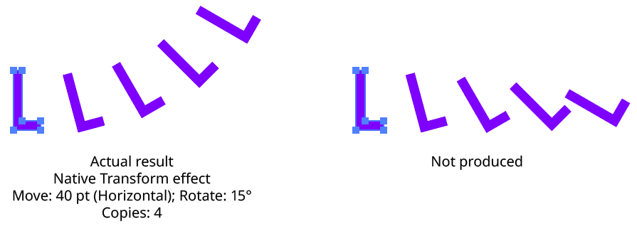
Native Transform Move Plus Rotate Example
The answer is due to two factors: the order of the transform operations, and the method of locating the center of rotation for each copy. For both the native Transform effect and AG Transform, each copy of the art is first scaled, then rotated, and finally moved (offset). The native Transform effect locates the center of rotation using the bounding box of the original art, and that center is used for all subsequent copies. Thus, the transform could be manually created as follows: Starting with the original art, a copy is made in place which is then rotated 15° around the center of rotation (the bounding box center). Then it is offset 40 pt to the right.
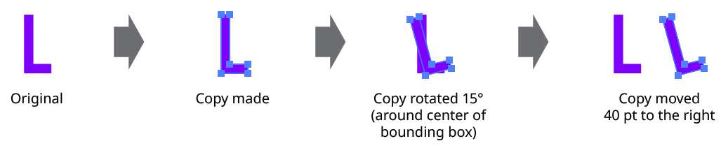
Native Transform Move Plus Rotate Manual Creation
This process is repeated for the second copy. Importantly, the center of rotation remains located at the center of the bounding box of the original art.
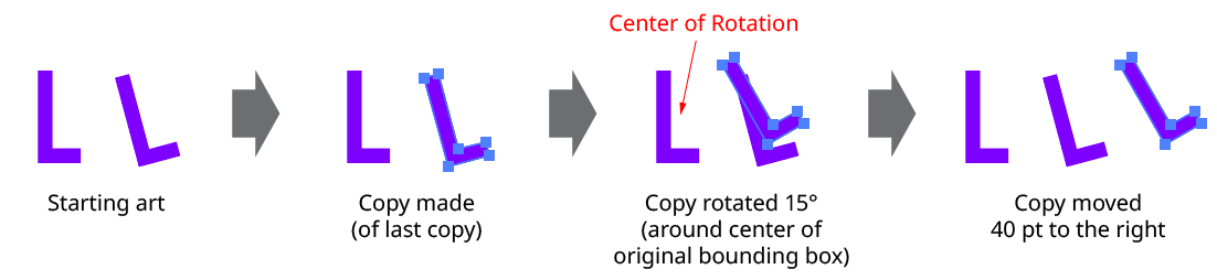
Native Transform Move Plus Rotate Manual Creation with Multiple Copies
The same steps are followed for each subsequent copy, which leads to the results shown originally.
AG Transform can be made to act like the native Transform effect for rotation by setting the Center of Rotation method to Relative to Bounds and the art type to Top-Level Art. However, the other two art types offer additional options:
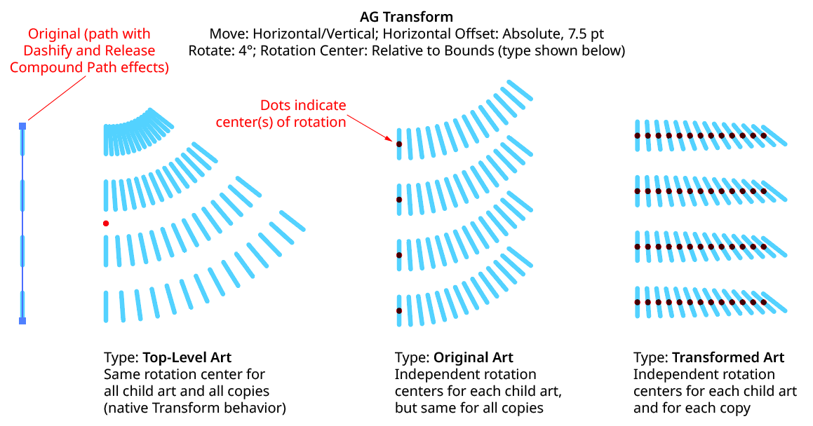
AG Transform Rotate Center Relative to Bounds Examples
Anchor Point: With this method, the center of rotation is located at the specified anchor point of the art at the specified grouping level. The rotation point is transformed for each copy, along with the art. If the art does not contain a path, the Relative to Bounds method will be used instead.

AG Transform Center of Rotation Anchor Point Controls
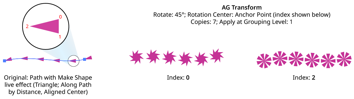
AG Transform Rotate Center Anchor Point Examples
Position Along Path: With this method, the center of rotation is located along the path of the art (from 0% to 100%) at the specified grouping level. The rotation point is transformed for each copy, along with the art. If the art does not contain a path, the Relative to Bounds method will be used instead.

AG Transform Center of Rotation Position Along Path Controls
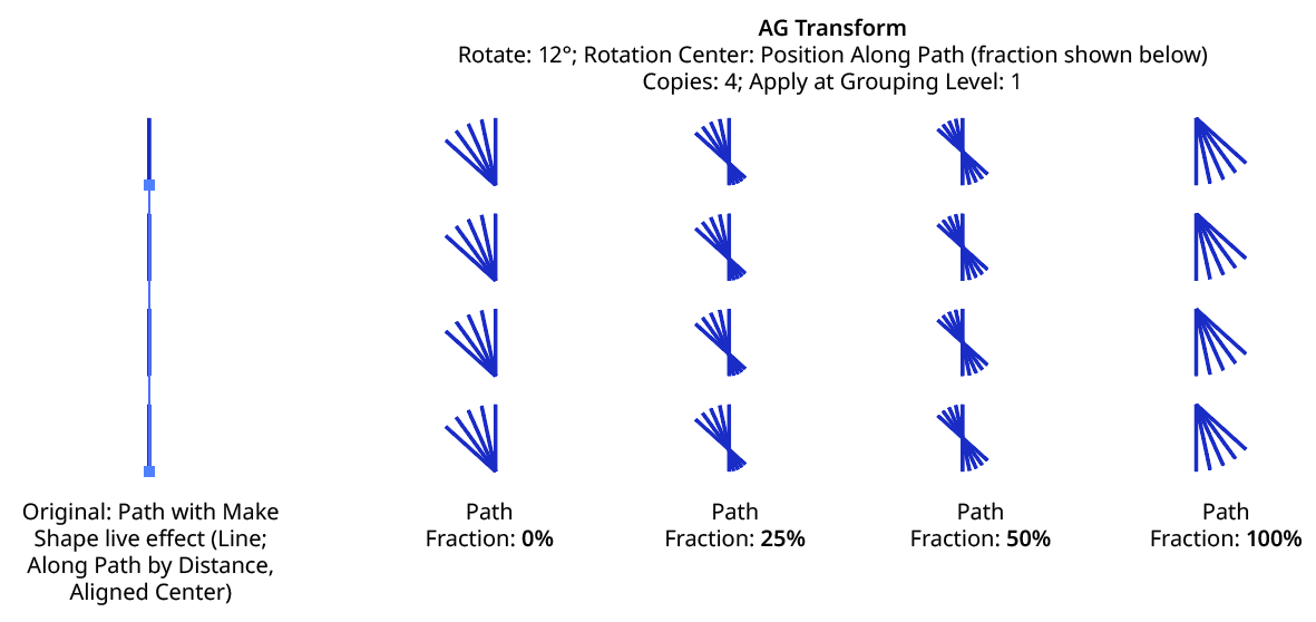
AG Transform Rotate Center Position Along Path Examples
Tagged Path: With this method, the center of rotation is located at the first anchor point of a path contained in the top-level group that has the note “AGTransformRotatePath” (as entered on the native Attributes panel). It is customary to use a single-point path for this purpose, so the path won’t inadvertently be made visible. If no such path exists, AG Transform uses the first path it finds in the top-level art. If no paths at all exist, the Relative to Bounds method will be used instead.

AG Transform Center of Rotation Tagged Path Controls
Along Line: With this method, the center of rotation is located along an imaginary line that passes through two points which are located using anchor point indices and t-values in the path art at the specified grouping level. The rotation point is transformed for each copy, along with the art. If the art does not contain a path, the Relative to Bounds method will be used instead.

AG Transform Rotate Center Along Line Controls
A. Start Index: The index of the anchor point used to locate the start of the imaginary line.
B. Start T-Val: The t-value (bezier-derived distance between the anchor point and the next anchor point, ranging from 0 to 1) of the start point.
C. End Index: The index of the anchor point used to locate the end of the imaginary line.
D. End T-Val: The t-value (bezier-derived distance between the anchor point and the next anchor point, ranging from 0 to 1) of the end point.
E. Fraction: The position of the center of rotation, as a fraction of the distance between the start point of the imaginary line and the end point. Values between 0% and 100% would put this point between the start and end, but the value can also be negative or greater than 100% to put the point outside this interval.
The Along Line method is similar to the Relative to Bounds method in that the center of rotation is always relative to the artwork. However, while Relative to Bounds only offers nine distinct positions, Along Line can specify an infinite number of such positions.
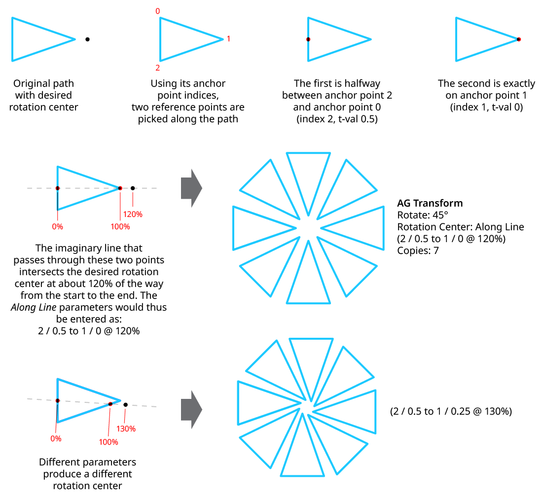
AG Transform Rotate Center Along Line Examples
8. Randomize
Randomization works the same way in the Rotate section of the dialog as it does in the Angle area of the Move section (when in Distance/Angle mode). Step values can be set for both the regular rotation value and for the per-copy change value.
Illustrator Location:
The Scale section of the dialog has the following controls:
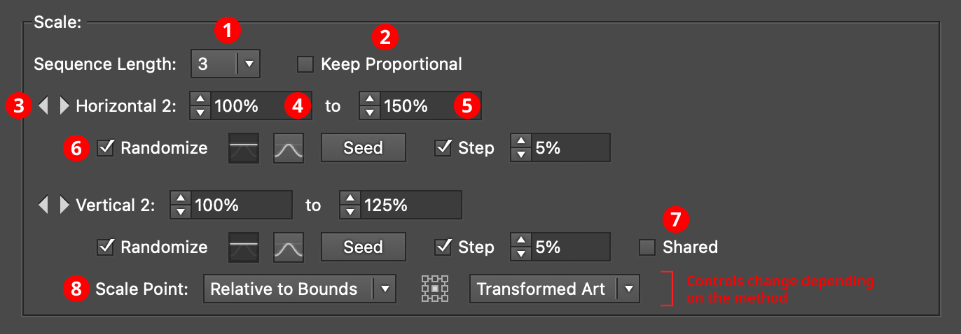
AG Transform Parameters Dialog - Scale Section
1. Rotation Sequence Length
By default (and ignoring randomization), each copy receives the same scaling value (as with the native Transform effect). However, AG Transform offers sequences, which allow up to 8 different scaling values. If the number of copies exceeds the length of the sequence, the values simply repeat in a cycle. Each member of a sequence shares the same randomization parameters.
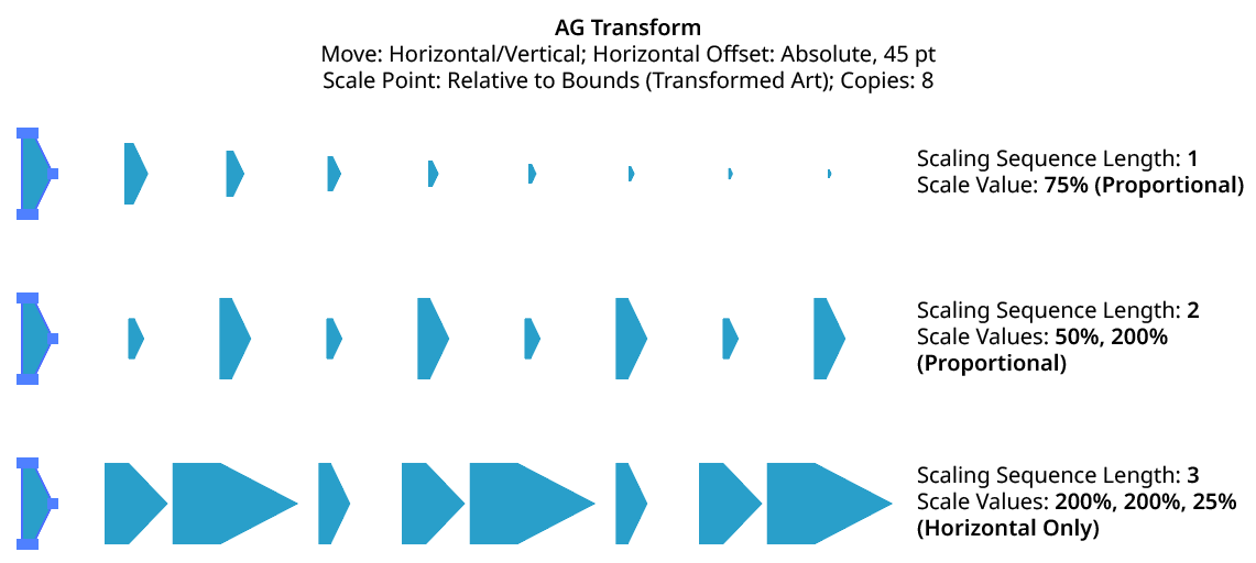
AG Transform Scaling Sequence Examples
2. Keep Proportional
When enabled, scaling will always be proportional (the vertical scaling values will be automatically set to match the horizontal scaling values).
3. Previous/Next Offset Buttons
Available when the sequence length is set to a value other than 1. Clicking either button will move between the sequence’s values, allowing any of them to be edited.
4. Value/Minimum Value
The horizontal (or vertical) scaling value for the current sequence index, from –10000% to 10000%. Negative values have the effect of flipping the object across the corresponding axis (the same as using the Reflect X or Reflect Y checkboxes in the native Transform dialog). When randomization is enabled, this value specifies the minimum value that may be randomly produced.
5. Maximum Value
Available when randomization is enabled; it specifies the maximum horizontal (or vertical) scaling value that may be randomly produced for the current sequence index.
6. Randomize
Randomization works the same way in the Scale section of the dialog as it does in the Move section. Both horizontal and vertical scaling can have independent randomization parameters.
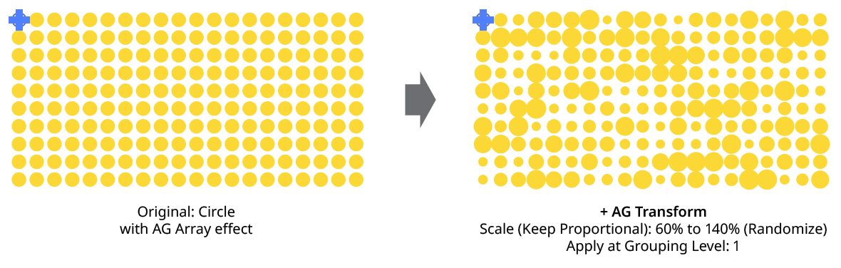
AG Transform Random Scale
7. Shared
When enabled, the random number for each copy (i.e., its random position between the specified minimum and maximum) will be the same for the vertical scaling as the horizontal scaling, allowing the transformed aspect ratio of each copy to be maintained.
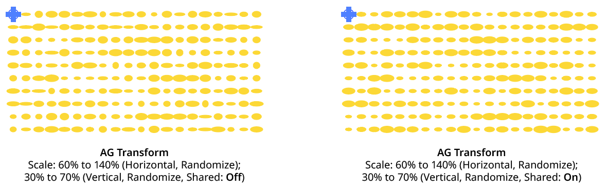
AG Transform Random Scale (Non-Shared Vs. Shared)
8. Scale Point
Just as with specifying the Center of Rotation, the dropdown menu allows the choice between six different methods of specifying the point through which the art is scaled: Fixed, Relative to Bounds, Anchor Point, Position Along Path, Tagged Path, or Along Line. See Center of Rotation in the Rotate section for an explanation of the methods.
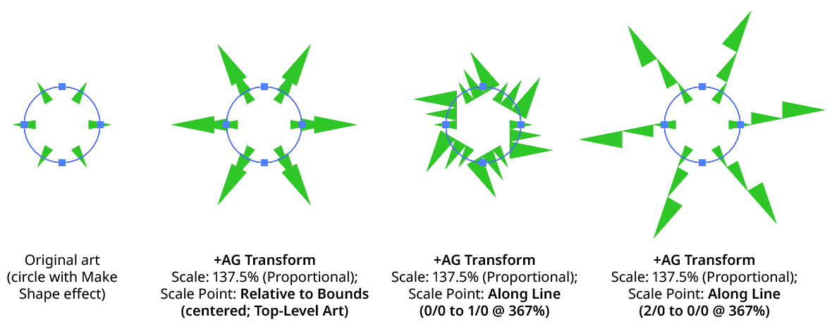
AG Transform Scale Point Examples
Illustrator Location:
The Bottom section of the dialog has the following controls:
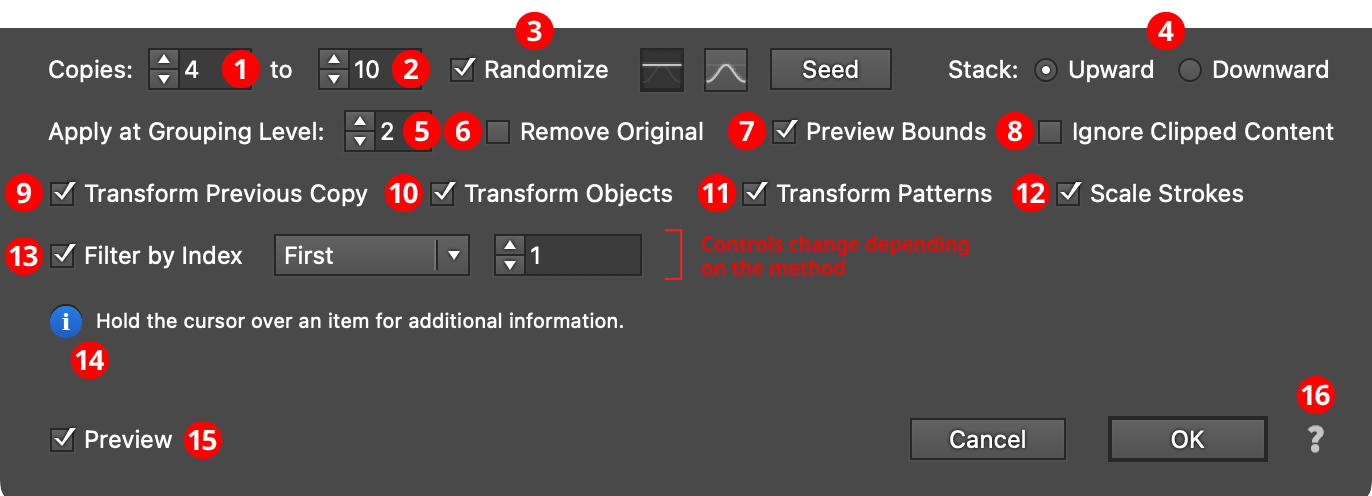
AG Transform Parameters Dialog - Bottom Section
1. Copies
The number of copies to make for each art object at the specified grouping level. This is the same as the setting in the native Transform effect. When copy randomization is enabled, this value represents the minimum number of copies that may be randomly produced.
2. Maximum Copies
Available when copy randomization is enabled; it specifies the maximum number of copies that may be randomly produced.
3. Copies Randomize
When randomization is enabled, the number of copies is not fixed for each object, but is chosen randomly between the specified minimum and maximum values. The distribution of those values (linearly or in a Gaussian manner) can be specified, as well as the random seed.
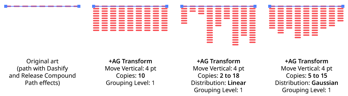
AG Transform Copy Randomization Examples
4. Stack
Specifies whether each copy is created upward or downward in the stacking order (the native Transform effect always stacks downward).
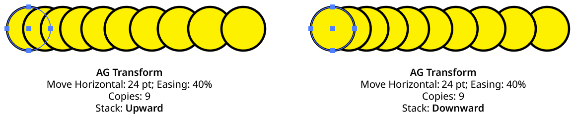
AG Transform Stacking Order
5. Apply at Grouping Level
Unless a live effect is applied above all strokes and fills (a “pre” effect), or inside a stroke or a fill and above other live effects, the art object internally passed to it is always a group. And this group may contain other groups, and so on. The Grouping Level controls the level at which the effect is applied, which affects what elements in the hierarchy get different random transformations as well as how the center of rotation and scale point are calculated. The Grouping Level can range from 0 (representing the top-level art) to 29 (the deepest level of group nesting allowed in Illustrator).
In the simplest case (when AG Transform is applied to a single stroked-and-filled path), the live effect mechanism separates the stroke from the fill, and passes a stroke-only path and a fill-only path to the live effect in a group. So while a Grouping Level of 0 would apply the same transformation to the stroke and fill (because it is applied to the top-level group), a Grouping Level of 1 would cause it to consider the stroke and fill as separate objects, and if randomization was on, they would get different random values:
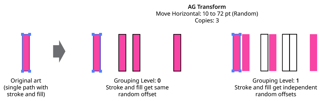
AG Transform Grouping Level on Simple Path
Next, consider the case of applying AG Transform to a group of stroked and filled paths. This top-level group may or may not have its own stroke and/or fill in its appearance. Here, the group passed to the effect has three groups inside it. One is composed of the paths with group level strokes (if there is no group level stroke, these would have no stroke or fill); another is composed of the paths with group level fills (similarly, if there is no group level fill, these would also have no stroke or fill); and the last is composed of the original paths in the group (and here, strokes and fills are not broken apart).
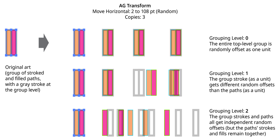
AG Transform Grouping Level on Group of Paths
In general, each nested group in the original art requires two Grouping Levels to “dig into,” due to the fact that a group stroke or fill can be present at each level. Because it can be difficult to anticipate what Grouping Level to use because the live effect mechanism can be complicated, it is recommended to simply increase the Grouping Level until the results are what is desired (modifying the seed or seeds, if necessary, to see what is really changing independently). Setting the Grouping Level above the highest “valid” value will not cause a problem.
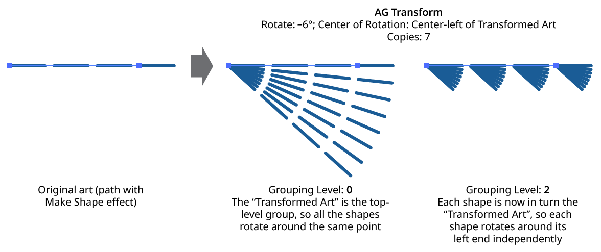
AG Transform Grouping Level and Rotation Center
6. Remove Original
Available if the number of copies is greater than zero. When enabled, the original art to which the effect was applied will be suppressed in its final appearance. This is often useful when using random transformations but the original is regular and spoils the random look.
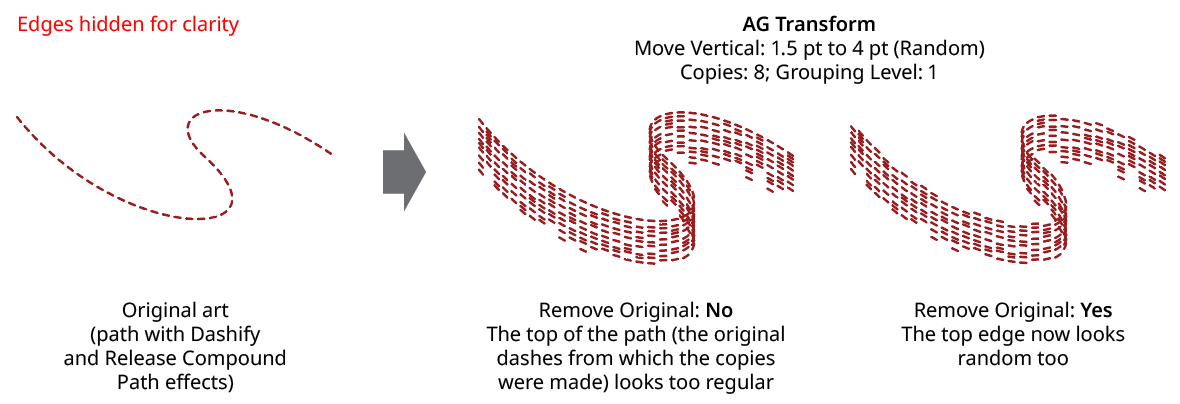
AG Transform Remove Original
7. Use Preview Bounds
Overrides the general preference of the same name. When enabled, the strokes of the artwork are included in its bounding box, which affects the position of the Center of Rotation or Scale Point when they are set to Relative to Bounds:
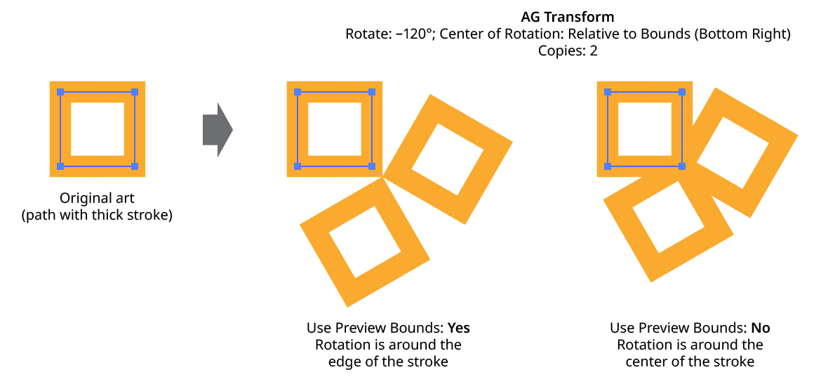
AG Transform Use Preview Bounds
8. Ignore Clipped Content
When enabled, and the art is a clip group, then only the clipping path is used for the purposes of bounds determination. This affects, for instance, the Move offsets when in Relative mode, or the position of the Center of Rotation or Scale Point when they are set to Relative to Bounds.
9. Transform Previous Copy
By default (and as with the native Transform effect), each copy after the first is created by transforming the previous copy. However, when using randomization, it can sometimes be useful to always start with the original art’s position and transform it to create each copy:
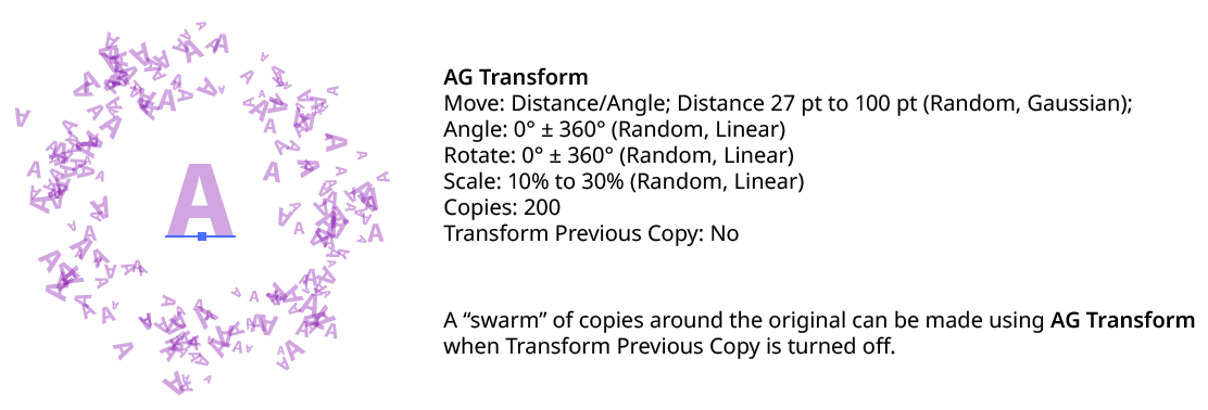
AG Transform Transform Previous Copy
10. Transform Objects
This option works the same as that for the native Transform effect. When disabled, only the pattern(s) contained in the art are transformed.
11. Transform Patterns
This option works the same as that for the native Transform effect. When disabled, pattern(s) contained in the art are not transformed along with the art.
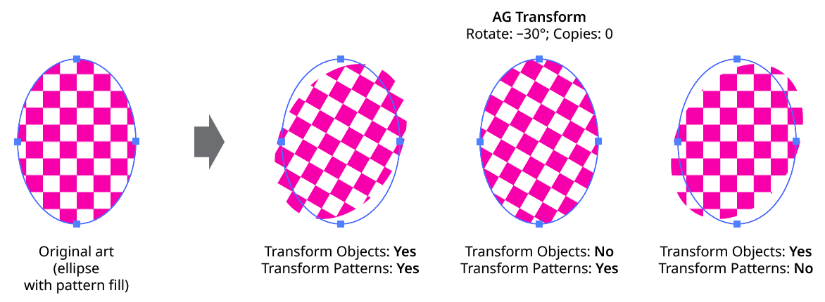
AG Transform Objects and Patterns
12. Scale Strokes
When disabled, and the AG Transform contains scaling, strokes within the artwork will retain their original weight.
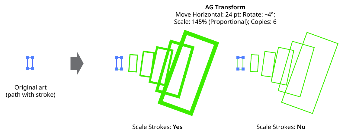
AG Transform Scale Strokes
13. Filter By Index
When enabled, each art object’s index is used to determine whether it should be transformed, using one of seven different methods. The index is simply an integer sequentially assigned to each object at the specified Grouping Level in the order it is encountered, starting with zero for the first object. Generally, the index increases going downwards in the stacking order; however, other live effects present in the appearance stack may change this order, sometimes randomly (such as PathFinder effects). Additionally, objects may be created which are invisible in the final appearance if they have no fill or stroke. The available By Index methods are as follows:
a. First: Only the first n objects are affected, where n is the specified value.

AG Transform Filter by Index - First Controls
b. Last: Only the last n objects are affected, where n is the specified value.

AG Transform Filter by Index - Last Controls
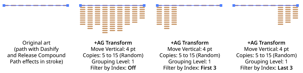
AG Transform Filter by Index - First, Last
c. First or Last: Only the first and last objects are affected.
d. Odd: Only objects with an odd index (1, 3, 5, 7...) are affected.
e. Even: Only objects with an even index (0, 2, 4, 6...) are affected.
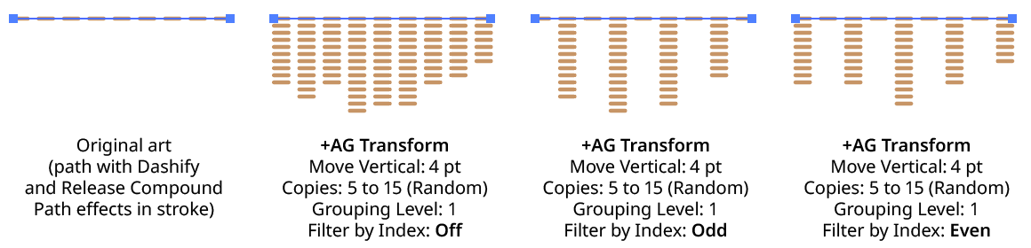
AG Transform Filter by Index - Odd, Even
f. Pattern: Creates a repeating pattern of matching indices based on the three pattern parameters.

AG Transform Filter by Index - Pattern Controls
Initial Skip specifies the number of indices to skip over at the start (art with these indices will not be affected). Then, Match specified the number of indices that will match and therefore be affected. Finally, Skip specifies the number of indices to skip over following the matching indices. When the total of the values in the three parameters is less than the number of eligible art objects, the pattern repeats, using the Match and Skip values in alternation.
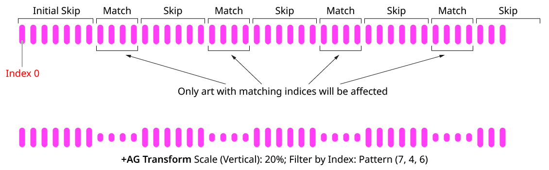
AG Transform Filter by Index - Pattern
g. Randomly: Each art object has the specified random chance (from 0% to 100%) of being affected. The parameter has an independent seed value. Just as with move/rotate/scale seed values, clicking the button picks a new seed, thereby changing the look of the artwork. To view or specify the seed number directly,
Option/Alt-clickthe button. This lets you recreate a previously-generated look.

AG Transform Filter by Index - Randomly Controls

AG Transform Filter by Index - Randomly
14. Informational area
Shows a brief description of each control when the cursor is being hovered over it.
15. Preview
As with all live effects, when enabled, changing a parameter will immediately update the artwork while the dialog is still open.
16. Help Button
Opens the help documentation in the Astute Manager. If this does not automatically appear, please ensure your Astute Manager is running first.
Illustrator Location:
Illustrator Main Menu > Effect > AG Utilities > Angle Cap
Angle Cap is an Astute Graphics live effect for stroked, open paths that allows for angled end caps, where the flat end of the stroke runs at an adjustable angle to the perpendicular of the path. The angle can be fixed at a certain value (for example, always horizontal), or can be relative to the path’s angle.
As with most live effects, Angle Cap appears in the main menu, under Effect > AG Utilities. It can also be applied directly from the Appearance panel using the “Add New Effect” button at the bottom of the panel.
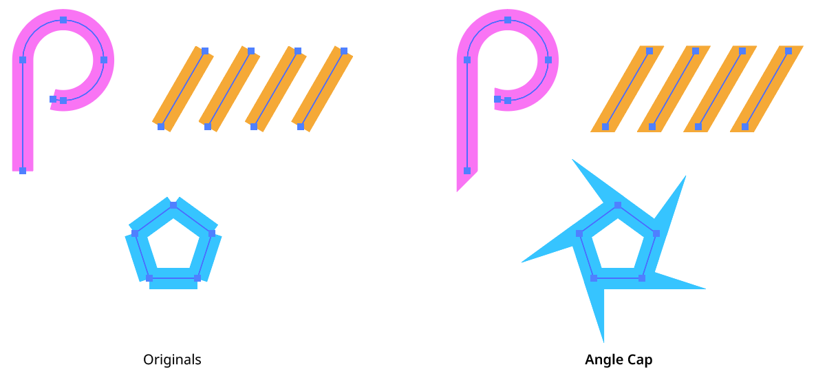
Angle Cap Live Effect Example
Angle Cap Parameters Dialog
After applying the live effect using the menu item (or when clicking on the existing effect in the Appearance panel to edit it), the parameters dialog will appear:
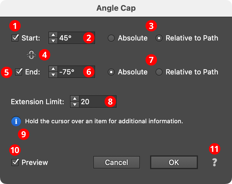
Angle Cap Parameters Dialog
1. Start
The Start checkbox enables or disables modification of the stroke cap at the start of the path.
2. Start Angle
Specifies the angle of the end of the stroke’s cap. In Absolute mode, this angle is fixed (does not depend on the path angle) and can range from –360° to 360° using the normal Illustrator convention of angles (0° is to the right):
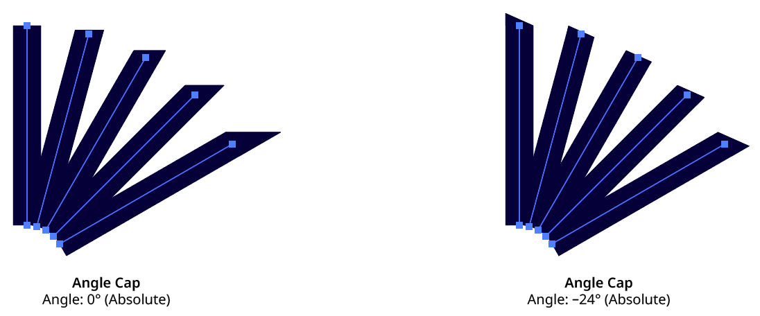
Angle Cap Absolute Mode
In Relative to Path mode, the angle is relative to a line drawn perpendicular to the path at its tip, and can range from –90° to 90°, where 0° means no change from the normal perpendicular angle:
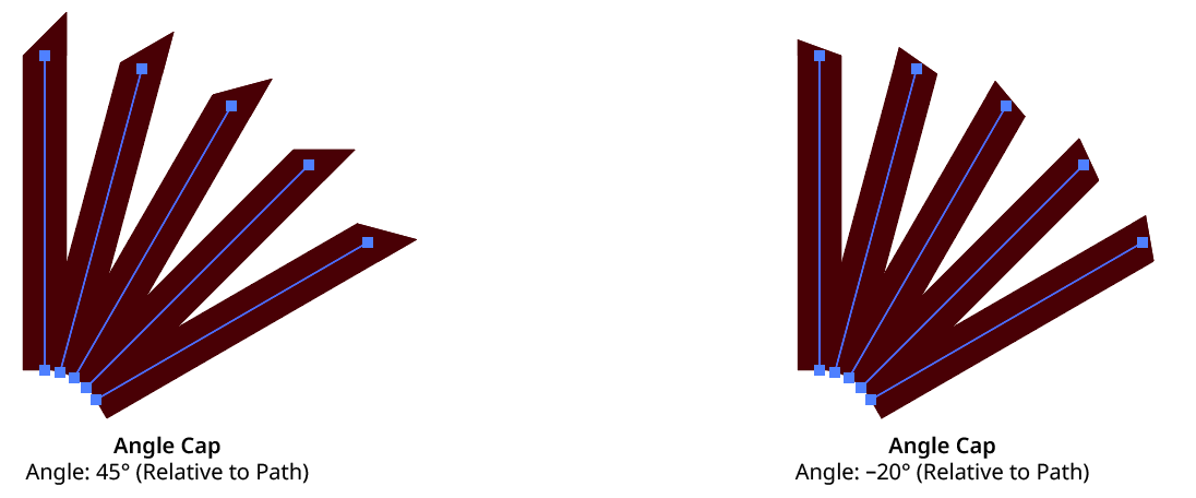
Angle Cap Relative to Path Mode
3. Start Absolute/Relative
Specifies the mode of the start cap angle (see Start Angle).
4. Link Start & End
Clicking on the icon toggles its state. When “linked,” making changes to either the Start or End parameters will simultaneously affect the opposite side.
5. End
The End checkbox enables or disables modification of the stroke cap at the end of the path.
6. End Angle
As per the Start angle, but for the end (last anchor point) of the path.
7. End Absolute/Relative
Specifies the mode of the end cap angle (see Start Angle).
8. Extension Limit
Similar to the native miter limit for corner joins, the Extension Limit is necessary to keep an angled cap from extending out infinitely as the cap’s angle gets closer and closer to the path’s tangent angle. The value represents the maximum length of the cap as a multiple of the path’s width, and can range from 5 to 500.
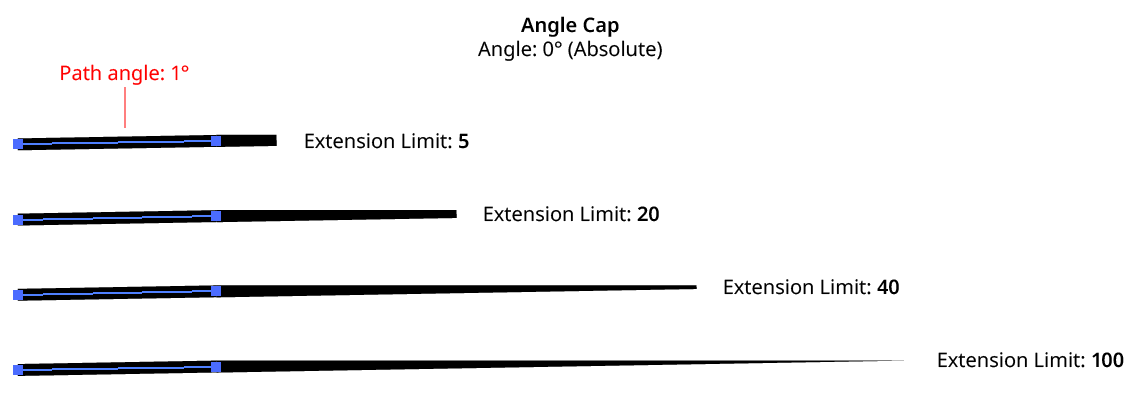
Angle Cap Extension Limit
9. Informational area
Shows a brief description of each control when the cursor is being hovered over it.
10. Preview
As with all live effects, when enabled, changing a parameter will immediately update the artwork while the dialog is still open.
11. Help Button
Opens the help documentation in the Astute Manager. If this does not automatically appear, please ensure your Astute Manager is running first.
Illustrator Location:
Angle Cap: Inside, Outside, and Variable Width Strokes
Because these types of strokes are actually converted to closed, filled paths inside the live effect mechanism, Angle Cap cannot be used with them.
Angle Cap: Dashed Strokes
When Aligned dashes are used, the dashes at the start and end of the path are generally converted to separate open paths inside the live effect mechanism, and thus will receive angle caps of their own, producing unexpected results. To put angle caps on each dash, use the Astute Graphics Dashify live effect instead of a dashed stroke.

Angle Cap with Dashes
Angle Cap: Strokes with Gradients
A plugin cannot actually change a stroke’s caps in Illustrator, so the Angle Cap live effect simulates them by placing an appropriately-shaped polygon at the end(s) of the path. This may be seen by expanding the live effect:
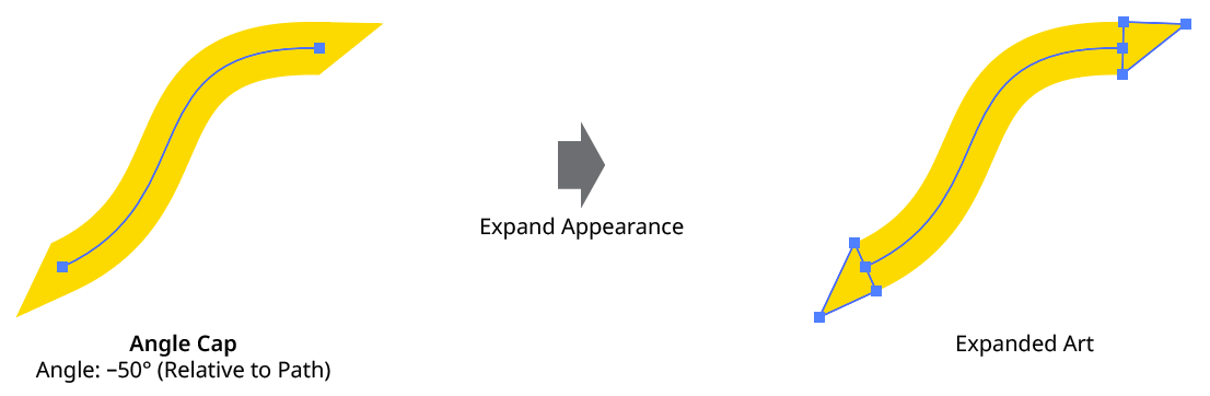
Angle Cap Expanded View
If the stroke has a gradient applied (the normal, “within the stroke” type — gradients along or across the stroke are converted to meshes inside the live effect mechanism and will not work with Angle Cap), Illustrator’s method of auto-positioning gradients will typically result in the caps visually not being seamless with the stroke. One way to remedy this is by placing the Angle Cap effect within the stroke and adding (directly above it) a native Pathfinder Add effect and an Astute Graphics Segment Removal effect (to change the path, which becomes a closed path after the Add effect, back to open).
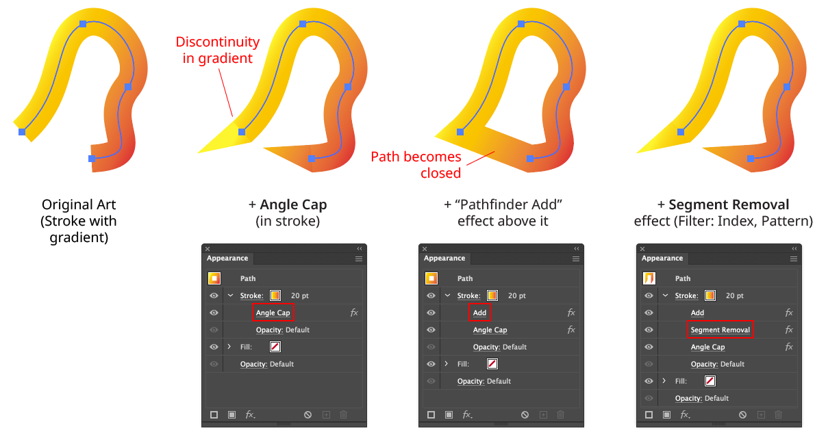
Angle Cap with Gradients
Note that with this method, because the native Add effect can change the starting point of the path, it may be necessary to adjust the Pattern/Initial Skip value in the Segment Removal effect to target the correct segment to remove:
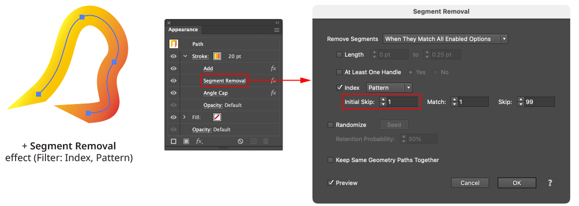
Angle Cap with Gradient - Segment Removal Example
Angle Cap: Strokes with Round or Projecting Caps
Angle Cap handles these types of existing caps by simply extending the cap polygon(s) to cover them.
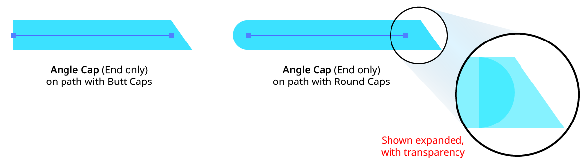
Angle Cap with Round Caps
Illustrator Location:
Close Path is an Astute Graphics live effect for open paths that closes them using one of three methods: using the existing handles (if any); with a straight segment; or with a smooth curve. If using a smooth curve, the scaling of the handles can be specified.
As with most live effects, Close Path appears in the main menu, under Effect > AG Utilities. It can also be applied directly from the Appearance panel using the “Add New Effect” button at the bottom of the panel.
Close Path Parameters Dialog
After applying the live effect using the menu item (or when clicking on the existing effect in the Appearance panel to edit it), the parameters dialog will appear:
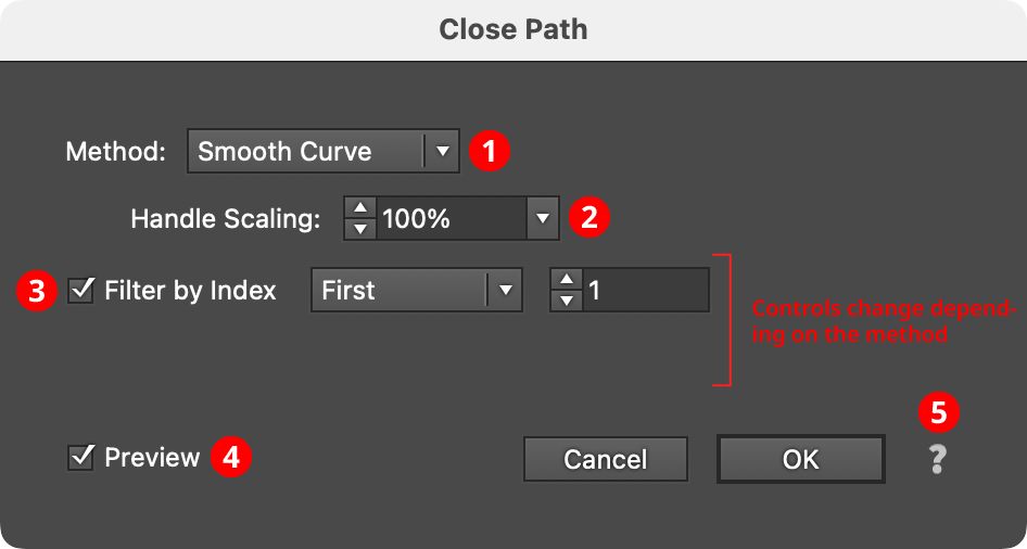
Close Path Parameters Dialog
1. Method
Specifies how the path will be closed. When set to Existing Handles, the path is simply marked as closed and the closing segment incorporates the outfacing handles (if any) that were present on the start and last segment of the open path (this may therefore result in a straight or curved segment, depending on those handles). When set to Straight Segment, the path is closed with a straight, handleless segment. When set to Smooth Curve, the path is closed using a curved bezier segment that joins the existing path smoothly (i.e., at the join locations, the new segment and the existing path have the same tangential angles).
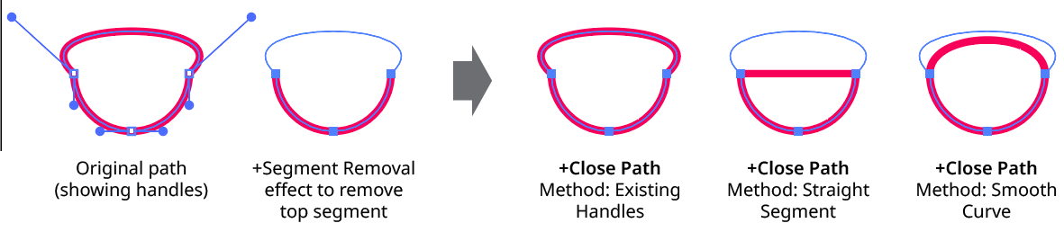
Close Path Method
2. Handle Scaling
Available when the method is set to Smooth Curve. It controls the length of the generated handles, as a percentage of the default value. Higher numbers produce a curve that “bulges” more.
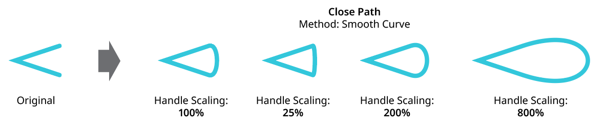
Close Path Handle Scaling
3. Filter By Index
When enabled (and the effect has been applied to a group or is inside a live effect stack which has internally created multiple objects), each art object’s index is used to determine whether it should be affected by the live effect, using one of seven different methods. The index is simply an integer sequentially assigned to each object in the order it is encountered, starting with zero for the first object. Generally, the index increases going downwards in the stacking order; however, other live effects present in the appearance stack may change this order, sometimes randomly (such as PathFinder effects). Additionally, objects may be created which are invisible in the final appearance if they have no fill or stroke. The available By Index methods are as follows:
a. First: Only the first n objects are affected, where n is the specified value.

Close Path Filter by Index First Controls
b. Last: Only the last n objects are affected, where n is the specified value.

Close Path Filter by Index Last Controls
c. First or Last: Only the first and last objects are affected.
d. Odd: Only objects with an odd index (1, 3, 5, 7...) are affected.
e. Even: Only objects with an even index (0, 2, 4, 6...) are affected.

Close Path Filter by Index, First, Last, Odd and Even
f. Pattern: Creates a repeating pattern of matching indices based on the three pattern parameters.

Close Path Filter by Index Pattern Controls
Initial Skip specifies the number of indices to skip over at the start (art with these indices will not be affected). Then, Match specified the number of indices that will match and therefore be affected. Finally, Skip specifies the number of indices to skip over following the matching indices. When the total of the values in the three parameters is less than the number of eligible art objects, the pattern repeats, using the Match and Skip values in alternation.
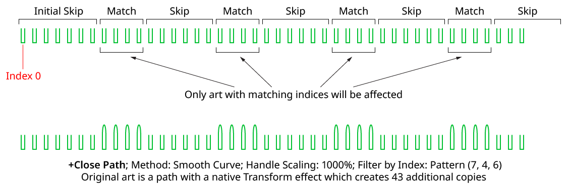
Close Path Filter by Index Pattern
g. Randomly: Each art object has the specified random chance (from 0% to 100%) of being affected. Clicking the Seed button picks a new random seed, thereby changing the look of the artwork. To view or specify the seed number directly,
Option/Alt-clickthe button. This lets you recreate a previously-generated look.

Close Path Filter by Index Randomly Controls
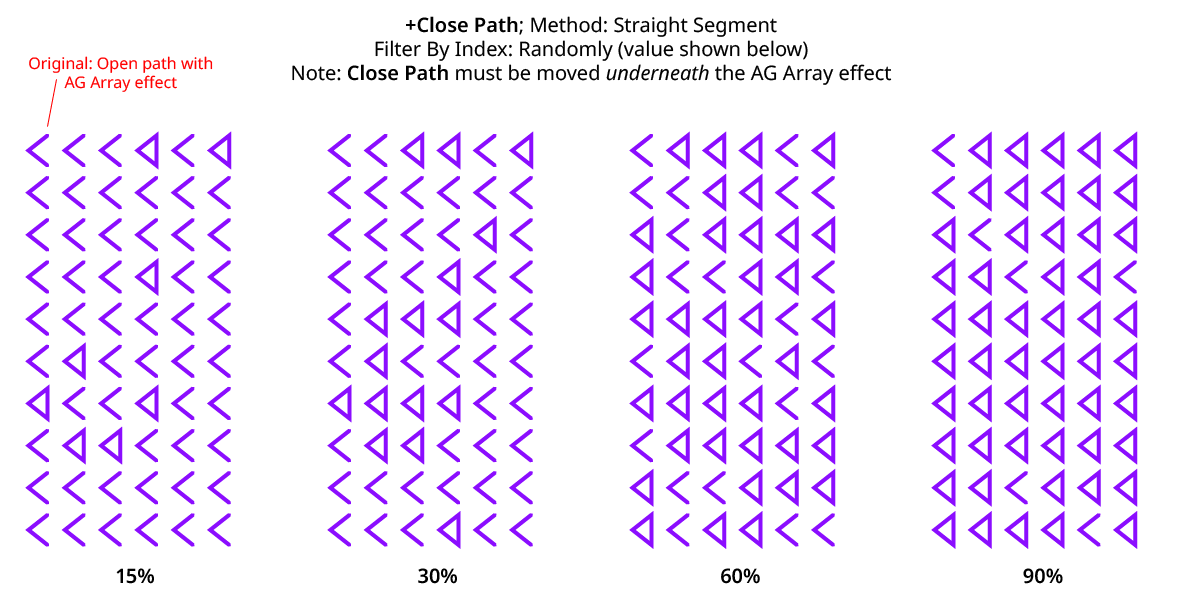
Close Path Filter by Index Randomly
4. Preview
As with all live effects, when enabled, changing a parameter will immediately update the artwork while the dialog is still open.
5. Help Button
Opens the help documentation in the Astute Manager. If this does not automatically appear, please ensure your Astute Manager is running first.
Illustrator Location:
Illustrator Main Menu > Effect > AG Utilities > ...
Convert to Smooth is an Astute Graphics live effect for paths that changes the anchor points in the artwork to smooth type, automatically adding and adjusting handles where needed.
As with most live effects, Convert to Smooth appears in the main menu, under Effect > AG Utilities. It can also be applied directly from the Appearance panel using the “Add New Effect” button at the bottom of the panel.
Convert to Smooth Parameters Dialog
After applying the live effect using the menu item (or when clicking on the existing effect in the Appearance panel to edit it), the parameters dialog will appear:

Convert to Smooth Parameters Dialog
1. Smoothing Ratio
Controls the lengths of any newly-generated handles. The smoothing ratio can range from 0.01 to 0.5, with values between 0.3 and 0.4 generally give the smoothest looking curves; a value of 0.3905 will convert a square to a circle.
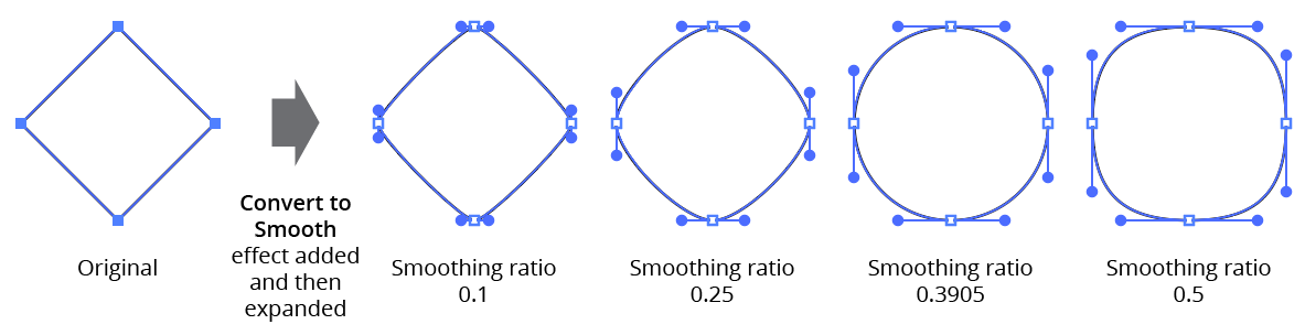
AG Utilities Live Effects - Convert to Smooth Ratios
2. Handleless Points Only
When enabled, only anchor points that have no handles will be converted to smooth points with new handles.
3. Preview
As with all live effects, when enabled, changing a parameter will immediately update the artwork while the dialog is still open.
4. Help Button
Opens the help documentation in the Astute Manager. If this does not automatically appear, please ensure your Astute Manager is running first.
Illustrator Location:
Illustrator Main Menu > Effect > AG Utilities > ...
Dashify is an Astute Graphics live effect for paths that breaks them into multiple segments that, if stroked, have the same look as native dashes. But unlike native dashes, when a path with Dashify is expanded, each dash is converted to a short, open section of a compound path rather than an outlined, filled and closed path. Additionally, Dashify supports five independent lengths for pairs of dashes and gaps, an additional alignment mode for open paths, and randomization options.
As with most live effects, Dashify appears in the main menu, under Effect > AG Utilities. It can also be applied directly from the Appearance panel using the “Add New Effect” button at the bottom of the panel.
Dashify Parameters Dialog
After applying the live effect using the menu item (or when clicking on the existing effect in the Appearance panel to edit it), the parameters dialog will appear:
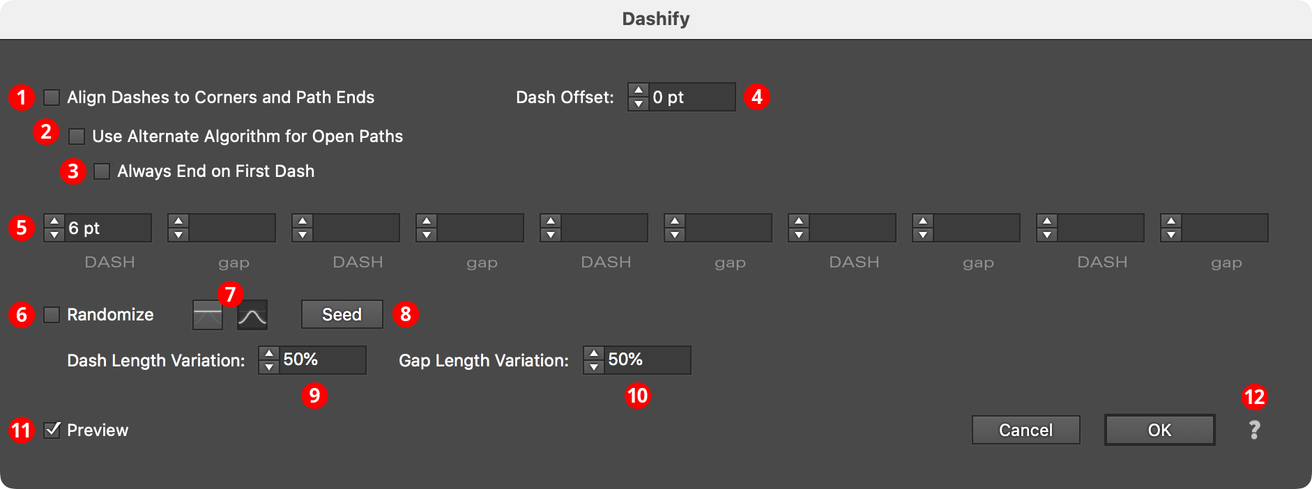
Dashify Parameters Dialog
1. Align Dashes to Corners and Path Ends
When enabled, dashes are aligned in the same manner as the native dashes are aligned using the native Stroke panel’s “Align” button. This may cause the absolute size of each dash and gap to be changed slightly.
2. Use Alternate Algorithm for Open Paths
Available when Align Dashes to Corners and Path Ends is enabled. When enabled, dashes are aligned such that each end of the open path gets a full dash rather than the half-dash that the native algorithm produces. Interior corners will be ignored for alignment purposes.
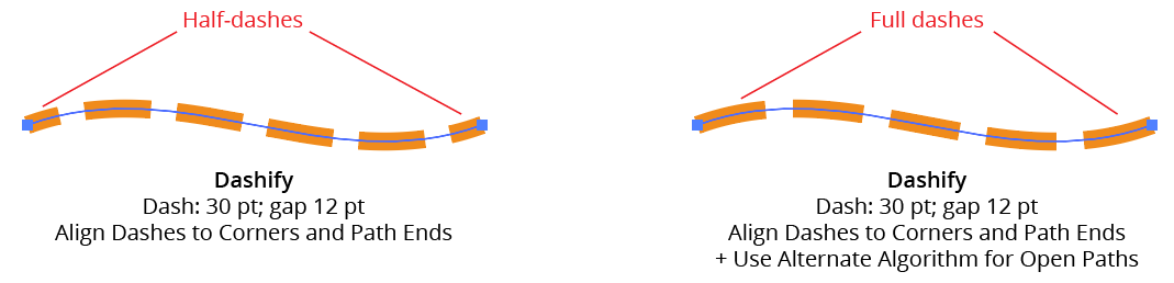
AG Utilities Live Effects - Dashify Alignment
3. Always End on First Dash
Available when the Alternate Algorithm for Open Paths is being used. When enabled, the dashed path will not only start with the first dash in the pattern but will also end with it:
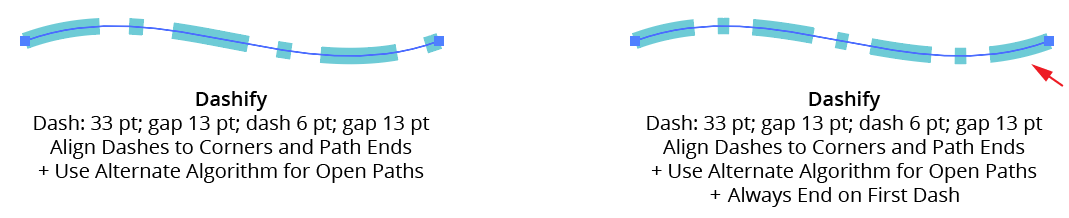
AG Utilities Live Effects - Dashify Alignment (Always end on first dash)
4. Dash Offset
Shifts the starting position of the dash pattern along the path. Positive values move the pattern in the path’s direction while negative values move it in the opposite direction. Dash Offset is not available when Align Dashes to Corners and Path Ends is enabled.
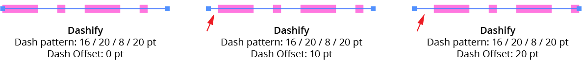
AG Utilities Live Effects - Dashify Dash Offset
5. Dashes and Gaps
As per the native Stroke panel, specifies the length of the dashes and gaps. Supports up to five pairs of values, (compared to three for the native panel). When using zero as a gap length, the path will still be broken into dashes; each will touch its neighbours. Zero can be useful as a dash length when combined with round end caps: it produces circular dots.
6. Randomize
Allows randomization of the lengths of the dashes and/or the gaps. Randomization is not available when Align Dashes to Corners and Path Ends is enabled.
7. Distribution Curves
Specifies either a linear distribution in random values (all values in the range are equally likely to be chosen) or a Gaussian distribution (central values in the range are more likely to be chosen).
8. Seed
Each random seed number leads to a different sequence of random values. Clicking the button picks a new seed, thereby changing the look of the artwork. To view or specify the seed number directly, Option/Alt-click the button. This lets you recreate a previously-generated look.
9. Dash Length Variation
Specifies the random variation in the length of each dash. For example, if a dash’s length is set to 20 pt, then a variation value of 25% would produce lengths that vary by as much as 20 pt × 25% = 5 pt, that is, between 15 pt and 20 pt; a variation value of 90% would produce lengths between 2 pt and 20 pt.
10. Gap Length Variation
As per Dash Length Variation, but for gaps.
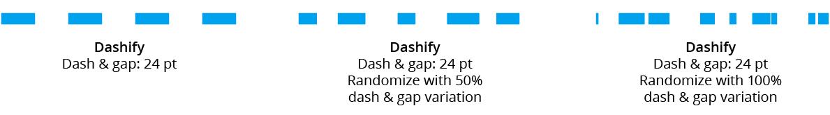
AG Utilities Live Effects - Dashify Randomization
11. Preview
As with all live effects, when enabled, changing a parameter will immediately update the artwork while the dialog is still open.
12. Help Button
Opens the help documentation in the Astute Manager. If this does not automatically appear, please ensure your Astute Manager is running first.
Illustrator Location:
Extend Path is an Astute Graphics live effect for open paths that allows them to be extended (lengthened) or shortened. Extension can be made using four different methods, and randomization options are available.
As with most live effects, Extend Path appears in the main menu, under Effect > AG Utilities. It can also be applied directly from the Appearance panel using the “Add New Effect” button at the bottom of the panel.
Extend Path Parameters Dialog
After applying the live effect using the menu item (or when clicking on the existing effect in the Appearance panel to edit it), the parameters dialog will appear:
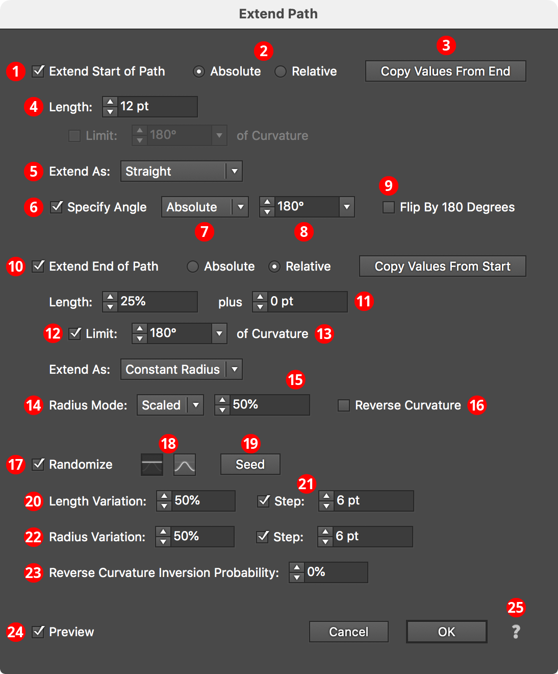
Extend Path Parameters Dialog
1. Extend Start of Path
Each end of the open path can be independently affected. The top section of the dialog pertains to the start of the path.
2. Absolute/Relative
Specifies whether the extension length is an absolutely-specified value (for example, 24 pt) or a value relative to the path length (for example, 50%, which would make the path 1.5 times as long as it was originally).
3. Copy Value button
Allows you to pick up all the parameters from the section of the dialog for the opposite end of the path, in cases where both ends of the path must be extended in the same manner.
4. Length
The amount that the path will be extended or shortened. In Relative mode, the value is interpreted as a percentage of the original path length. Negative values will result in the path being shortened instead of extended.
5. Extend As
The type of extension (ignored when shortening a path).
Bezier Extension
In Bezier extension mode, no additional anchor points are added to the path. Instead, the cubic bezier curve that comprises the path segment being extended is simply expanded. Due to the mathematics of cubic beziers, this may lead to situations where the curve turns in unexpected directions or even reverses direction at a cusp point if the original bezier had only a single handle.
Constant Radius Extension
In Constant Radius extension mode, the path is continued as a circular arc of constant radius. The radius value itself depends on which radius mode is active (see Radius Mode).
Straight Extension
In Straight extension mode (the default), the path is continued as a simple straight line.
Spiral Extension
In Spiral extension mode, the path is continued as a logarithmic spiral with the specified winding constant. Lower winding constants make the spiral’s radii become smaller more quickly.
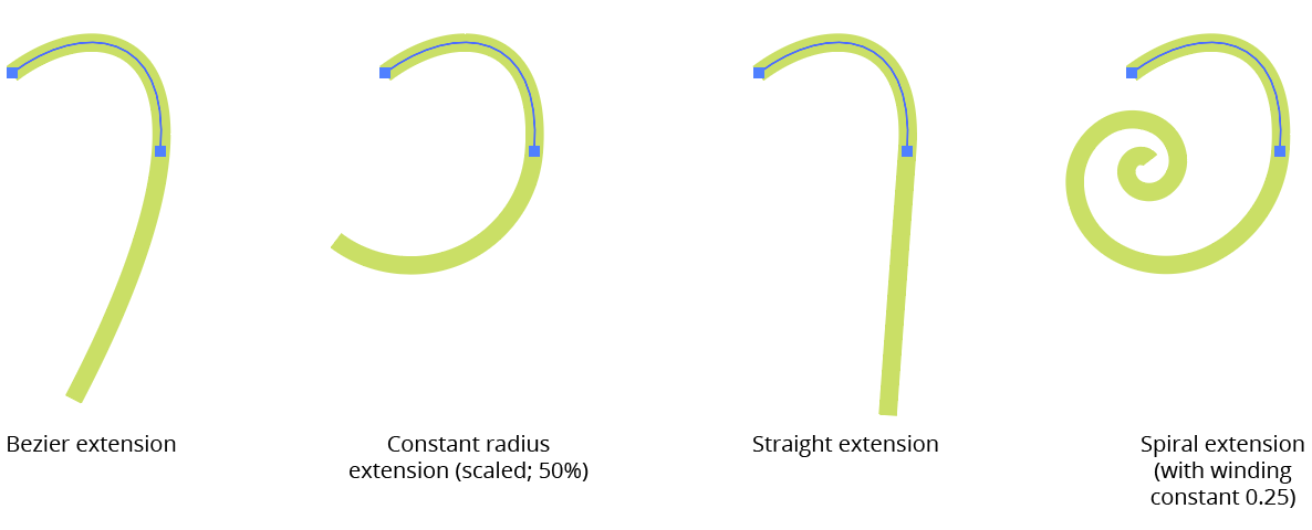
AG Utilities Live Effects - Path Extension Types
6. Specify Angle
Applicable with Straight extensions only; when enabled, the straight extension of the path will not be made at the original angle of the end of the path, but at the specified angle.
7. Specify Angle Mode
When specifying the straight extension angle, you can choose between an absolute angle or an angle that represents the change in angle (“Difference”) between the end of the path and the extension.
8. Specify Angle Value
The final angle, either as an absolute value or as a difference in angles.
9. Flip by 180 Degrees
The final angle is flipped by 180 degrees.
10. Extend End of Path
All controls are identical to the “Start of Path” section, but control the other end of the path.
11. Plus Value
For Relative mode extensions, allows an absolute value to be added to the relative value.
12. Limit Curvature
For Constant Radius and Spiral extensions, limits the length of the extension based on the amount of path bend.
13. Limit Curvature Value
The maximum amount of path bend (in degrees), regardless of length.
14. Radius Mode
For Constant Radius and Spiral extensions, one of the following: Match Radius Mode (the radius value will match the existing radius at the end of the path); Scaled Radius Mode (the radius value will be taken from the existing radius multiplied by the scale value); or Fixed Radius Mode (the radius value will be equal to the specified fixed value).
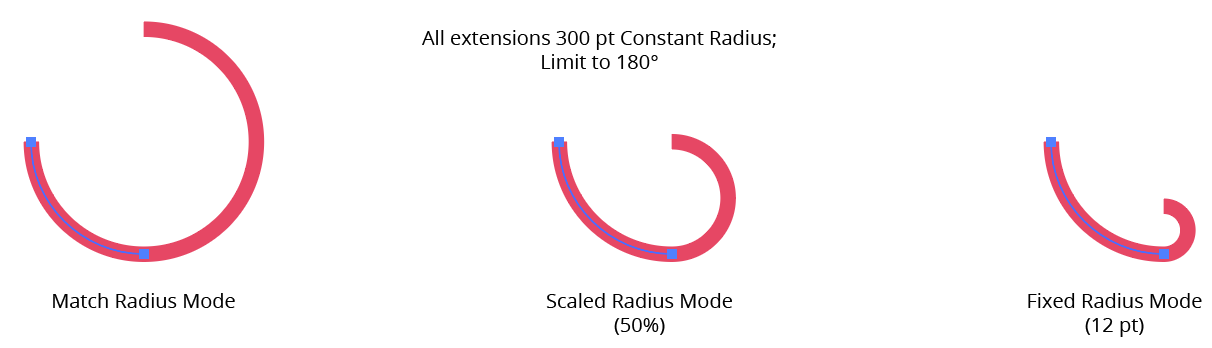
AG Utilities Live Effects - Extend Path Radius Modes
15. Radius Value
For Scaled and Fixed modes, the scale factor or fixed value.
16. Reverse Curvature
Normally the curvature of the extension is in the same direction as the existing path; Reverse Curvature makes the extension curve in the opposite direction.
17. Randomize
Allows randomization of several parameters, including length, radius, and the probability of reverse curvature. Randomization is most useful when applying the Extend Path effect to a group of many paths, or in an effect stack in which a previous effect breaks a single path into multiple pieces, like Dashify.
18. Distribution Curves
Specifies either a linear distribution in random values (all values in the range are equally likely to be chosen) or a Gaussian distribution (central values in the range are more likely to be chosen).
19. Seed
Each random seed number leads to a different sequence of random values. Clicking the button picks a new seed, thereby changing the look of the artwork. To view or specify the seed number directly, Option/Alt-click the button. This lets you recreate a previously-generated look.
20. Length Variation
Specifies the random variation in the length of the extension. For example, if the length is set to 20 pt, then a variation value of 25% would produce lengths that vary by as much as 20 pt × 25% = 5 pt, that is, between 15 pt and 20 pt; a variation value of 90% would produce lengths between 2 pt and 20 pt.
21. Length Step
Constrains each final extension length (after randomization) to multiples of the specified step value while still remaining in the original range. For example, if the extension length is set to 24 pt with a random variation of 50%, then normally values of 12 to 24 pt would be produced. But enabling Step with a value of 5 pt would result in only values of 15 pt and 20 pt.
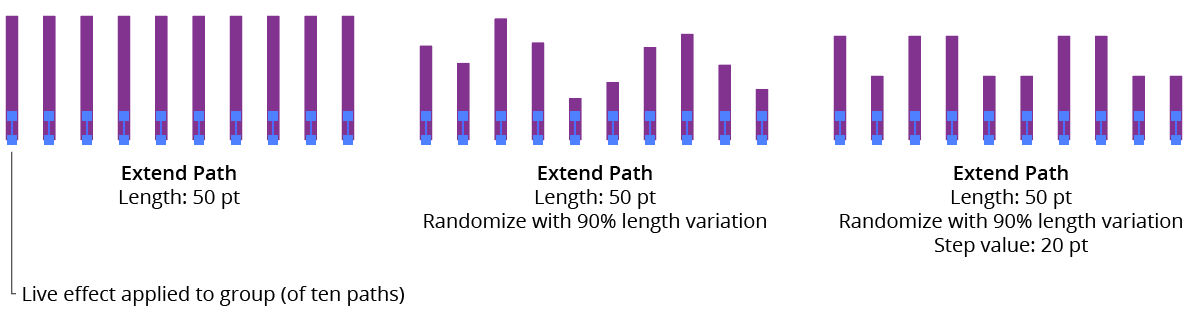
AG Utilities Live Effects - Extend Path Randomization
22. Radius Variation
For Constant Radius and Spiral extensions, similar to Length Variation but affects the final radius value.
23. Reverse Curvature Inversion Probability
For Constant Radius and Spiral extensions, specifies the probability that the reverse curvature setting (when enabled) will be inverted to the opposite value.
24. Preview
As with all live effects, when enabled, changing a parameter will immediately update the artwork while the dialog is still open.
25. Help Button
Opens the help documentation in the Astute Manager. If this does not automatically appear, please ensure your Astute Manager is running first.
Illustrator Location:
Illustrator Main Menu > Effect > AG Utilities > ...
Make Compound Path is an Astute Graphics live effect with one simple function: to turn multiple paths into a single compound path. It has no parameters.
As with most live effects, Make Compound Path appears in the main menu, under Effect > AG Utilities. It can also be applied directly from the Appearance panel using the “Add New Effect” button at the bottom of the panel.
The Make Compound Path effect is mainly useful when followed by a native PathFinder effect such as “Intersect”. For example, if a group of four circles has an “Intersect” effect applied, normally nothing happens. But if it is preceded by Make Compound Path, then the Boolean operation works as expected:
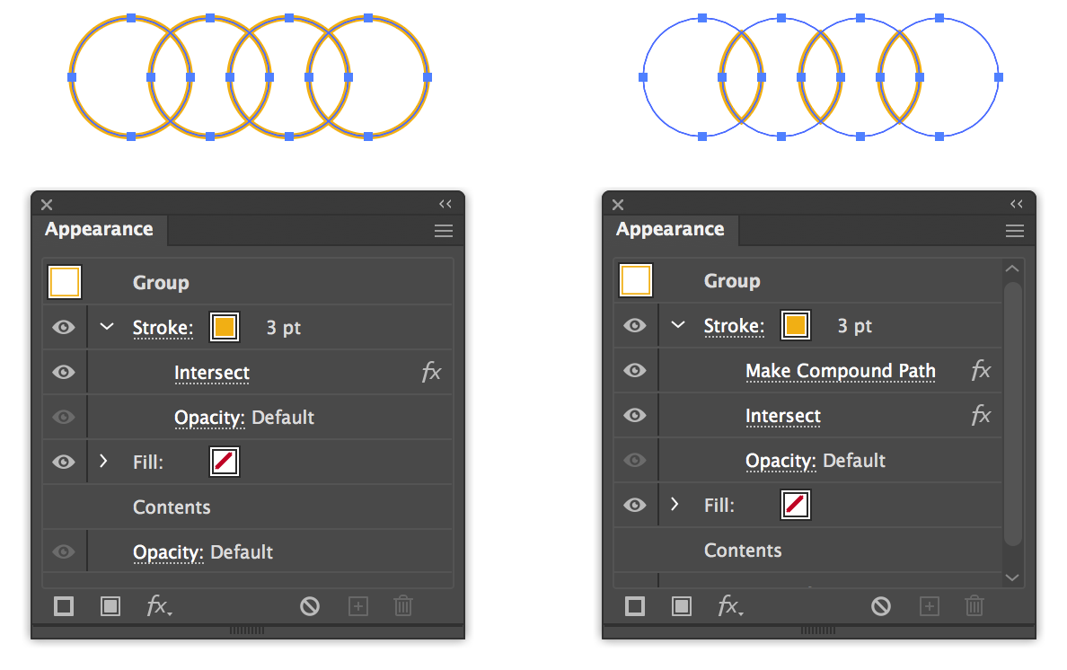
AG Utilities Live Effects - Make Compound Path
Illustrator Location:
Make Shape is an Astute Graphics live effect that creates paths which are basic geometric shapes from the artwork to which it is applied. In its basic form it is similar to the native “Convert to Shape” effect, but it includes many more parameters and options, such as the ability to place the shapes above or under the original artwork, the ability to change the alignment, and angle of the shape, and the ability to place multiple copies of shapes along paths. Randomization options are also included.
As with most live effects, Make Shape appears in the main menu, under Effect > AG Utilities. It can also be applied directly from the Appearance panel using the “Add New Effect” button at the bottom of the panel.
Make Shape Parameters Dialog
After applying the live effect using the menu item (or when clicking on the existing effect in the Appearance panel to edit it), the parameters dialog will appear:
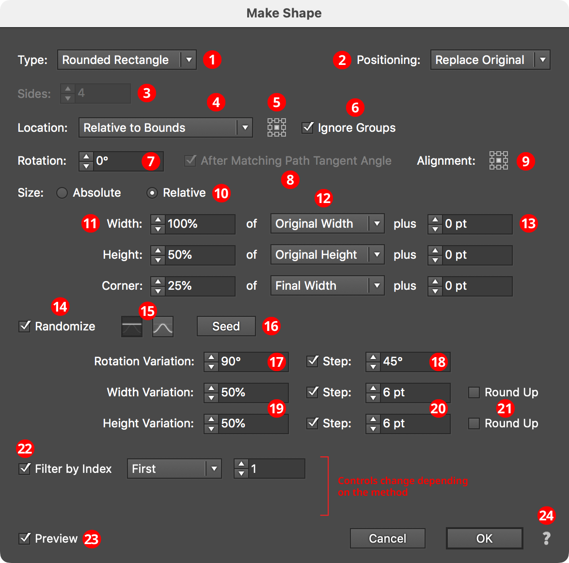
Make Shape Parameters Dialog
1. Shape Type
The type of shape to create, from among: Arc, Circle, Ellipse, Half-Circle, Line, Polygon, Rectangle, Rounded Rectangle, Square, Star, and Triangle. Depending on the type of shape selected, other parameter controls in the dialog may be hidden or changed.
2. Positioning
The position of the shape relative to the original artwork. It can replace the original (the default), or go above or below it.
3. Sides
Some of the shape types (Arc, Circle, Ellipse, Half-Circle, Polygon, and Star) allow the number of sides (anchor points for rounded shapes; points for stars) to be specified, from 3 to 1000. For Stars, an additional control will appear that lets you force the star to be “Regular” (this locks the ratio of its inner diameter to its outer diameter).
4. Location
Where to place the shape(s). The default, similar to the native “Convert to Shape” effect, is relative to the bounding box of the original artwork (note that Make Shape uses the outlines of live text to directly determine its bounding box). Other options (each will add parameter-specific controls alongside the popup menu) include:
Along Path (Once)

AG Utilities Live Effects - Make Shape Along Path Once
The shape is placed once along each path at the specified path length fraction (0 to 100%), where 0% indicates the start of the path and 100% indicates the end of the path; for closed paths, 0% and 100% refer to the same spot.
Along Path (By Count)

AG Utilities Live Effects - Make Shape Along Path by Count
The shape is placed the specified number of times along each path, equally spaced. For open paths, a shape is placed at each end except when Center is enabled: then the endpoints do not receive shapes and instead the shapes are placed along the interior of the path such that equal spacing would be maintained if multiple copies of the path were placed end-to-end. For closed paths, Center shifts the shapes such that they appear centered between the spots where they would be placed if Center were not enabled.
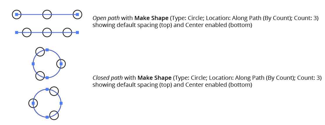
AG Utilities Live Effects - Make Shape Along Path by Count Center
Along Path (By Distance)

AG Utilities Live Effects - Make Shape Along Path by Distance
Shapes are placed along each path, starting at the first anchor point, with the specified distance between shapes. When Adjust is enabled, the spacing is modified in one of two different ways. In Center mode, the shapes are moved to be centered within the path. In Fit mode, the distance value is changed to the closest value which produces an integral number of shapes along the path.
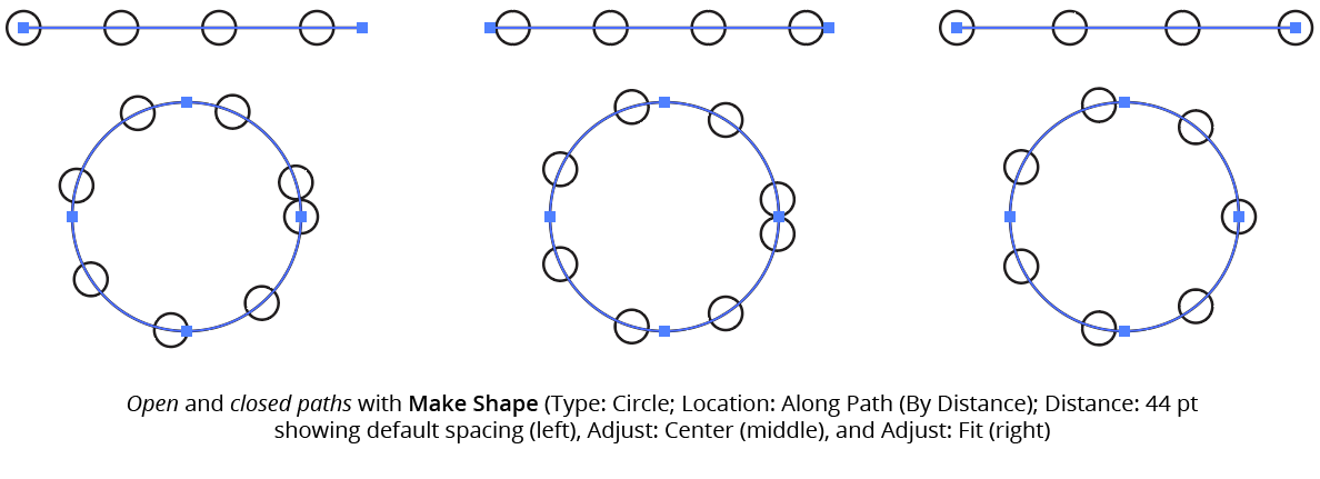
AG Utilities Live Effects - Make Shape Along Path by Distance Example
If the distance exceeds the path length, then no shapes are created unless Adjust is enabled.
Along Each Segment

AG Utilities Live Effects - Make Shape Along Each Segment
Shapes are placed along segments of each path at the specified length fraction (0 to 100%), where 0% indicates the start of the segment and 100% indicates the end of the segment. By default, all segments are included, but this can be changed to First, Last, Even Only, Odd Only, Curved Only, or Straight Only to affect only a subset of the segments.
At Anchor Points

AG Utilities Live Effects - Make Shape at Anchor Points
Shapes are placed at the positions of the anchor points of each path. By default, all anchor points are included, but this can be changed to First, Last, Even Only, Odd Only, Corner Only, or Smooth Only to affect only a subset of the anchor points.
5. Nine-block Control
When using a Location of Relative to Bounds, allows the picking of one of the nine standard positions (upper-left, upper-center, etc.) to which the shape can be oriented relative to the bounding box.
6. Ignore Groups
When using a Location of Relative to Bounds, when enabled, bounds are calculated separately for each member of any group in the original art (including groups created internally by the live effect mechanism), thereby resulting in multiple shapes if the group has more than one object (such as live text).
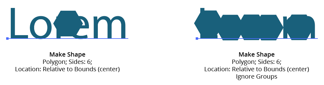
AG Utilities Live Effects - Make Shape Ignore Groups
7. Rotation
Specifies the rotation of the shape. This rotation value may be in addition to path tangent-matching rotation (see below).
8. After Matching Path Tangent Angle
This option is available when the location is set to anything other than Relative to Bounds. When enabled, the shape is first rotated to match the tangent angle at its spot along the path, and then any additional rotation specified by the rotation option is added to that value. Angles at corner points are determined by averaging the angles on either side of the point.
9. Alignment
Specifies the alignment of the shape to its nominal center point. This alignment is calculated with the shape in an unrotated state and any rotation is then carried out around the alignment point.
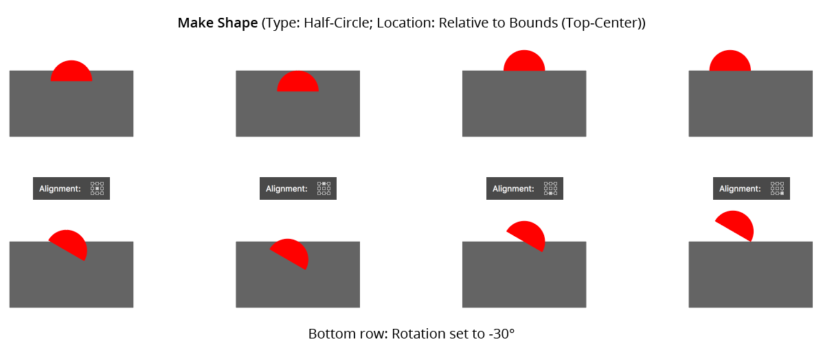
AG Utilities Live Effects - Make Shape Alignment
10. Size
When set to Absolute, the dimensions of the shape are set directly. When Relative, each dimension is based on another dimension, specified using the menu.
11. Dimensional Values
Sets the dimension(s) of the shape (shape types of Arc, Circle, Half-Circle, Line, Polygon, and Square have only a single dimension; Rounded Rectangle has three dimensions).
12. Dimensional Relative
For size Relative, specifies what the dimension is based on. For example, a circle’s diameter can be set to 50% of the original width of the art. For shape types with two or more dimensions, one dimension can be based on the other to determine its aspect ratio (for example, an ellipse’s width can be set to 200% of its height).
13. Plus Value
For size mode Relative, specifies an additional value that is added to the relatively-derived dimension, essentially giving it a minimum value.
14. Randomize
Allows randomization of the rotation and dimensions of the shapes.
15. Distribution Curves
Specifies either a linear distribution in random values (all values in the range are equally likely to be chosen) or a Gaussian distribution (central values in the range are more likely to be chosen).
16. Seed
Each random seed number leads to a different sequence of random values. Clicking the button picks a new seed, thereby changing the look of the artwork. To view or specify the seed number directly, Option/Alt-click the button. This lets you recreate a previously-generated look.
17. Rotation Variation
Specifies the maximum amount of variation in the final rotation of the shapes (in either clockwise or counter-clockwise directions), in degrees. For example, if the rotation value is set to 90° and the variation is set to 15°, possible values would be between 75 and 105°.
18. Rotation Step
Constrains each final rotation value (after randomization) to multiples of the specified step value while still remaining in the original range. In the example above, where possible values range continuously between 75 and 105°, setting the step value to 10° would instead only result in values of 80°, 90° or 100°.
19. Dimensional Variations
Specifies the random variation in the first dimension of the shape. For example, using a Line shape, if the length is set to 20 pt, then a variation value of 25% would produce lengths that vary by as much as 20 pt × 25% = 5 pt, that is, between 15 pt and 20 pt; a variation value of 90% would produce lengths between 2 pt and 20 pt.
20. Dimensional Steps
Constrains each final shape dimension (after randomization) to multiples of the specified step value while still remaining in the original range. For example, using a Line shape, if the length is set to 24 pt with a random variation of 50%, then normally values of 12 to 24 pt would be produced. But enabling Step with a value of 5 pt would result in only values of 15 pt and 20 pt.
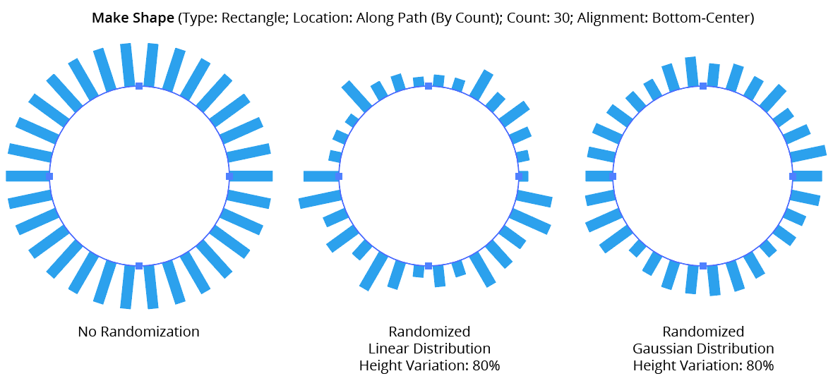
AG Utilities Live Effects - Make Shape Randomization
21. Round Up
When constraining a dimensional value to steps, enabling this setting ensures that the stepped (quantized) value is always higher then the non-quantized value. For example, suppose Make Shape were used to place a rectangle behind live text, but the rectangle needed to be a multiple of 20 pt wide. Without Round Up, the rectangle would sometimes become narrower than the text:
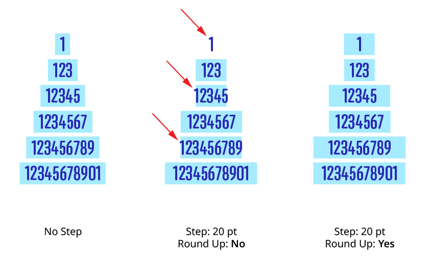
Make Shape Step Round Up
22. Filter By Index
When enabled (and the effect has been applied to a group or is inside a live effect stack which has internally created multiple objects), each art object’s index is used to determine whether it should have a shape made from it, using one of seven different methods. The index is simply an integer sequentially assigned to each object in the order it is encountered, starting with zero for the first object. Generally, the index increases going downwards in the stacking order; however, other live effects present in the appearance stack may change this order, sometimes randomly (such as PathFinder effects). Additionally, objects may be created which are invisible in the final appearance if they have no fill or stroke. The available By Index methods are as follows:
a. First: Only the first n objects are affected, where n is the specified value.

Make Shape Filter By Index - First Controls
b. Last: Only the last n objects are affected, where n is the specified value.

Make Shape Filter By Index - Last Controls
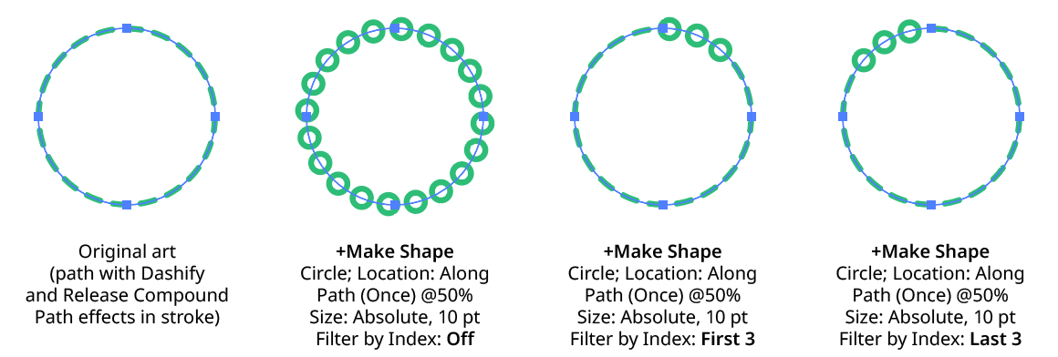
Make Shape Filter By Index - First, Last
c. First or Last: Only the first and last objects are affected.
d. Odd: Only objects with an odd index (1, 3, 5, 7...) are affected.
e. Even: Only objects with an even index (0, 2, 4, 6...) are affected.
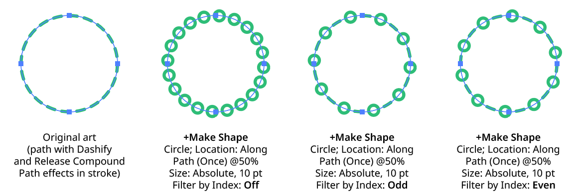
Make Shape Filter By Index - Odd, Even
f. Pattern: Creates a repeating pattern of matching indices based on the three pattern parameters.
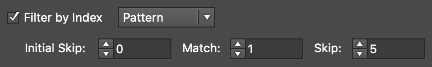
Make Shape Filter By Index - Pattern Controls
Initial Skip specifies the number of indices to skip over at the start (art with these indices will not be affected). Then, Match specified the number of indices that will match and therefore be affected. Finally, Skip specifies the number of indices to skip over following the matching indices. When the total of the values in the three parameters is less than the number of eligible art objects, the pattern repeats, using the Match and Skip values in alternation.
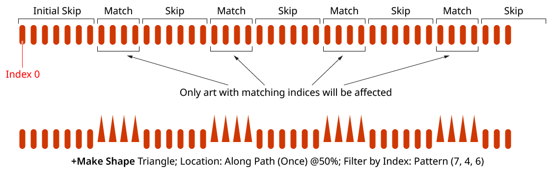
Make Shape Filter By Index - Pattern
g. Randomly: Each art object has the specified random chance (from 0% to 100%) of being affected. The parameter has an independent seed value. Just as with move/rotate/scale seed values, clicking the button picks a new seed, thereby changing the look of the artwork. To view or specify the seed number directly,
Option/Alt-clickthe button. This lets you recreate a previously-generated look.

Make Shape Filter By Index - Randomly Controls
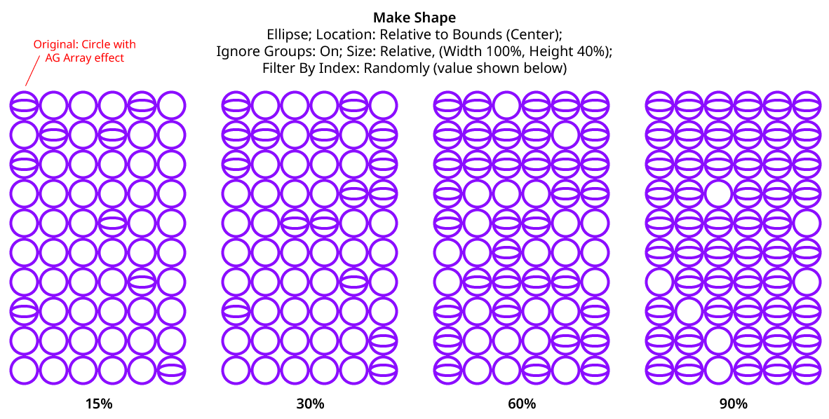
Make Shape Filter By Index - Randomly
23. Preview
As with all live effects, when enabled, changing a parameter will immediately update the artwork while the dialog is still open.
24. Help Button
pens the help documentation in the Astute Manager. If this does not automatically appear, please ensure your Astute Manager is running first.
Illustrator Location:
Illustrator Main Menu > Effect > AG Utilities > ...
Path Removal is an Astute Graphics live effect that removes paths from the object it is applied to, based on criteria such as path length, type (open/closed), or index. It is most useful when applied to a group of many paths, or is preceded by another live effect which breaks one path into many, such as Astute’s Dashify or Split Path to Segments.
As with most live effects, Path Removal appears in the main menu, under Effect > AG Utilities. It can also be applied directly from the Appearance panel using the “Add New Effect” button at the bottom of the panel.
Path Removal Parameters Dialog
After applying the live effect using the menu item (or when clicking on the existing effect in the Appearance panel to edit it), the parameters dialog will appear:

Path Removal Parameters Dialog
1. Criteria Popup
By default, paths will be removed only if they match all of the enabled options (the first six checkboxes below). However you can change this to When They Match Any Enabled Options, Unless They Match All Enabled Options, or Unless They Match Any Enabled Options.
2. Point Count
Paths match when they have an anchor point count from the minimum to the maximum values specified. The defaults are both 1, meaning paths will match if they are single points. When compound paths are treated as a whole, the anchor point count is the sum of all the anchor points in all subpaths.
3. Length
Paths match when they have a length from the minimum to the maximum values specified. When compound paths are treated as a whole, the length is the sum of the lengths of all subpaths.
4. Type
Paths match when their type is the same as specified. When compound paths are treated as a whole, they match if all of the subpaths match.
5. Subpaths of a Compound Path
Paths match as specified.
6. Segments With Handles
When set to Yes, paths match if any of their segments have handles; when set to No, paths match if none of their segments have handles.
7. Index
Paths match if their index matches the specified indices. Paths are assigned indices starting at zero, increasing in the order in which they are encountered within the live effect. The default type of index match is Odd, i.e. 1, 3, 5, 7, etc. Other options are First, Last, First or Last, Even, and Pattern. Pattern type creates a repeating pattern of matching indices based on the three subsequent parameters.
8. Initial Skip
For Pattern index matching, the initial number of indices to skip over.
9. Match
For Pattern index matching, the number of indices to match after skipping some.
10. Skip
For Pattern index matching, the number of indices to skip over after matching some.
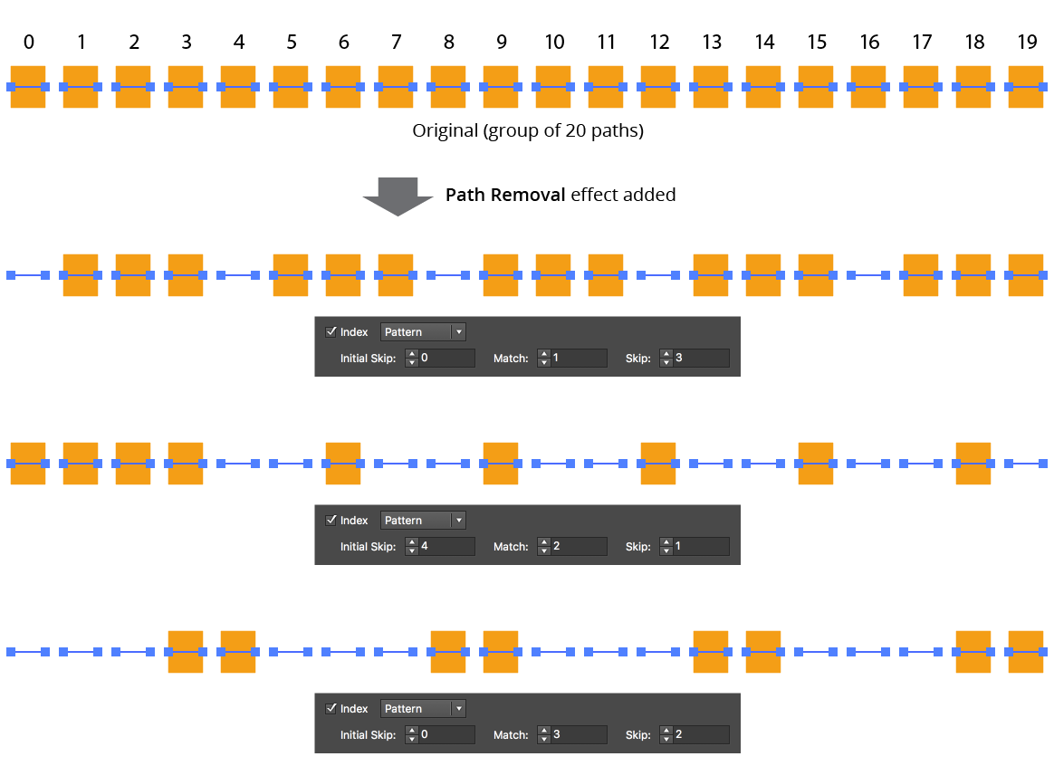
AG Utilities Live Effects - Path Removal Pattern
11. Randomize
Allows randomization of the removal.
12. Seed
Each random seed number leads to a different sequence of random values. Clicking the button picks a new seed, thereby changing the look of the artwork. To view or specify the seed number directly, Option/Alt-click the button. This lets you recreate a previously-generated look.
13. Retention Probability
The probability that a path that would normally be removed under the previous criteria will instead be retained. This value can be fixed (the default) or based on the index.
14. Retention Probability Value
For Fixed probability, the fixed value that applies to all removed paths. When the probability is set to Indexed, it consists of a starting probability value and an ending probability value, which linearly changes based on the index of the path.
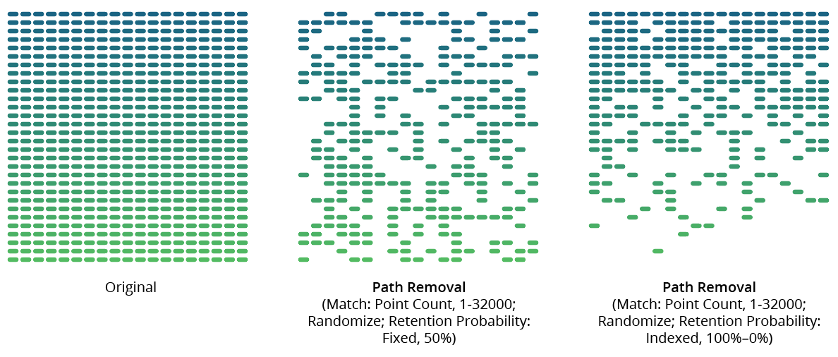
AG Utilities Live Effects - Path Removal Randomization Retention
15. Keep Same Geometry Paths Together
When the Path Removal effect is positioned under an artwork’s strokes and fills in the Appearance panel, the stroked and filled paths are passed to it separately, and would therefore normally be randomly affected independently, leading to some paths being stroked but not filled and vice versa. Sometimes this can be solved by simply moving the Path Removal effect above them in the Appearance panel, but depending on the other effects that are present, this may not always be possible. In that case, enabling this setting allows paths with the exact same underlying geometry (such as fills and strokes of the same path) to be retained or removed in a unified manner.
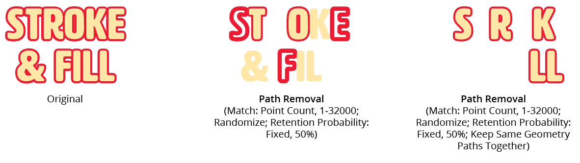
AG Utilities Live Effects - Path Removal Keep Same Geometry Together
16. Treat Compound Paths As a Whole
Normally each subpath of a compound path is examined for possible removal independently. When this setting is enabled, compound paths are either removed in their entirety or retained in their entirety. Some of the match parameters are interpreted slightly differently (for example, Point Count is interpreted to mean the total number of anchor points in all of the compound path’s subpaths).
17. Preview
As with all live effects, when enabled, changing a parameter will immediately update the artwork while the dialog is still open.
18. Help Button
Opens the help documentation in the Astute Manager. If this does not automatically appear, please ensure your Astute Manager is running first.
Illustrator Location:
Illustrator Main Menu > Effect > AG Utilities > ...
Path Visualizer is an Astute Graphics live effect that provides the visualization of anchor points, handles, and redundant points on a path or live text by rendering them as art elements. These art elements remain visible even if the path is not selected. Path Visualizer can be useful when evaluating various fonts (no need to create outlines), and when building large effect stacks; by temporarily inserting it at a certain location in the stack (and hiding effects below it), the state of the path(s) at that point in the effect chain can be visualized without having to expand the effect.
As with most live effects, Path Visualizer appears in the main menu, under Effect > AG Utilities. It can also be applied directly from the Appearance panel using the “Add New Effect” button at the bottom of the panel.
Path Visualizer Parameters Dialog
After applying the live effect using the menu item (or when clicking on the existing effect in the Appearance panel to edit it), the parameters dialog will appear:

Path Visualizer Parameters Dialog
1. Visualize Anchor Points
Creates a filled square at each anchor point on the path. At default 100% scaling, the squares have a side length of 5 pt.
2. Visualize Handles
Creates a filled circle at each bezier handle on the path. At default 100% scaling, the circles have a diameter of 5 pt.
3. Visualize Handle Lines
Creates a straight line from each handle to its associated anchor point on the path. At default 100% scaling, the lines have a stroke weight of 0.75 pt.
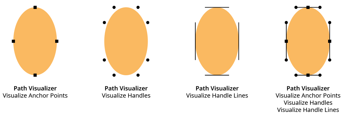
AG Utilities Live Effects - Path Visualizer Example
4. Visualize Redundant Points
Draws a semi-transparent red, triangular shape similar to the Astute Graphics PathScribe tool redundant point indicator over redundant points. A redundant point, also known as a doubled point, is defined as the latter of two consecutive anchor points on a path that have exactly the same X and Y coordinates and don’t have handles in the (zero-length) segment between them. They are often created after using the PathFinder functions or after using Object > Path > Outline Stroke, and despite not changing the shape of the path, can cause problems when performing additional functions such as offsetting.
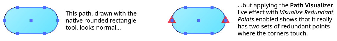
AG Utilities Live Effects - Path Visualizer Redundant Points
5. Include Unpainted Paths
When enabled, paths that have no fill or stroke are included when generating the visualization art. This is generally only necessary when placing the Path Visualizer effect above the fills and strokes in the Appearance panel.
6. Scale
Makes all the visualization art smaller or larger by the specified amount. The annotations that typically show anchor points and handles are independent of the zoom value, but since the live effect visualizations create actual art, they will get larger when the art is zoomed in on. This can make it difficult to see points that are very close to each other, very short handles, etc. The Scale factor can vary from 0.1% to 10000%.
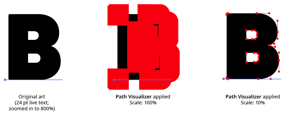
AG Utilities Live Effects - Path Visualizer Scale Example
7. Positioning
The position of the visualization art relative to the original artwork. It can replace the original, go above it (the default), or go below it.
8. Color
The color of the visualization art for anchor points, handles, and handle lines. The default color is black, but it can be changed by clicking on the color chip to bring up the standard color picker.
9. Preview
As with all live effects, when enabled, changing a parameter will immediately update the artwork while the dialog is still open.
10. Help Button
Opens the help documentation in the Astute Manager. If this does not automatically appear, please ensure your Astute Manager is running first.
Illustrator Location:
Illustrator Main Menu > Effect > AG Utilities > ...
Point Removal is an Astute Graphics live effect that removes anchor points from the paths in the artwork to which it is applied, based on criteria such as their distance from the previous point, the change in path angle at the point, or index. In contrast to the Smart Remove Points live effect, the handles of non-removed points are not adjusted to try to maintain path geometry.
As with most live effects, Point Removal appears in the main menu, under Effect > AG Utilities. It can also be applied directly from the Appearance panel using the “Add New Effect” button at the bottom of the panel.
Point Removal Parameters Dialog
After applying the live effect using the menu item (or when clicking on the existing effect in the Appearance panel to edit it), the parameters dialog will appear:

Point Removal Parameters Dialog
1. Criteria Popup
By default, points will be removed only if they match all of the enabled options (the first four checkboxes below). However you can change this to When They Match Any Enabled Options, Unless They Match All Enabled Options, or Unless They Match Any Enabled Options.
2. Distance From Previous
Points match when their distance (measured along the path) to the previous anchor point is between the minimum and the maximum values specified. The first point on an open path will never be matched.
3. Change In Path Angle
Points match when the change in the tangent angle of the path at the point is between the minimum and maximum values specified. Smooth points (unless malformed) will always have a 0° change in angle. The endpoints of an open path will never be matched.
4. Handles
Points match when their number of handles match the specified value: None, Any, Exactly One, or Exactly Two.
5. Index
Points match if their index matches the specified indices. Points are assigned indices starting at zero, increasing in the order in which they are encountered within the live effect. The default type of index match is Odd, i.e. 1, 3, 5, 7, etc. Other options are First, Last, First or Last, Even, and Pattern. Pattern type creates a repeating pattern of matching indices based on the three subsequent parameters.
6. Initial Skip
For Pattern index matching, the initial number of indices to skip over.
7. Match
For Pattern index matching, the number of indices to match after skipping some.
8. Skip
For Pattern index matching, the number of indices to skip over after matching some.
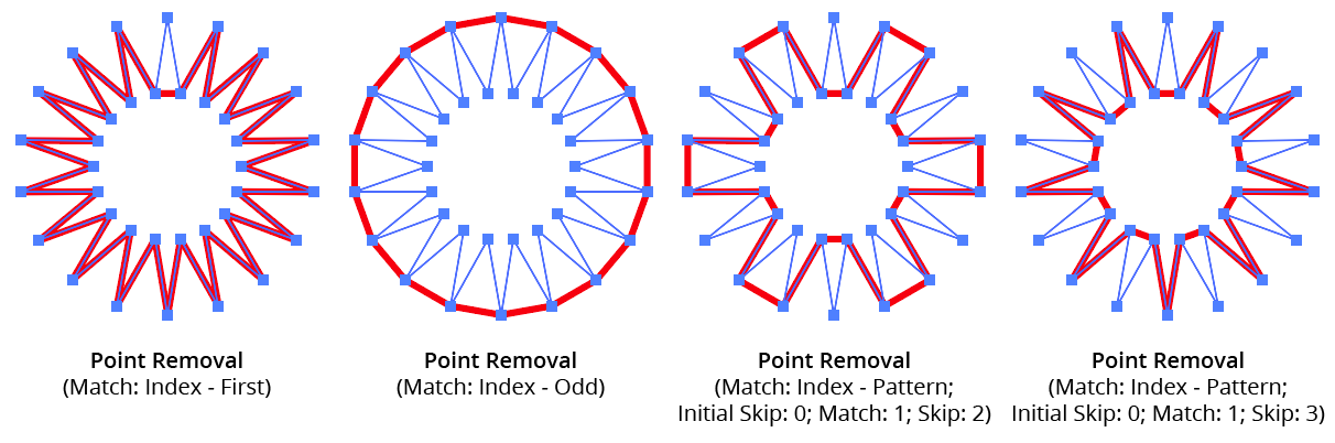
AG Utilities Live Effects - Point Removal Pattern
9. Randomize
Allows randomization of the removal.
10. Seed
Each random seed number leads to a different sequence of random values. Clicking the button picks a new seed, thereby changing the look of the artwork. To view or specify the seed number directly, Option/Alt-click the button. This lets you recreate a previously-generated look.
11. Retention Probability
The probability that a point that would normally be removed under the previous criteria will instead be retained.
12. Keep Same Geometry Paths Together
When the Point Removal effect is positioned under an artwork’s strokes and fills in the Appearance panel, the stroked and filled paths are passed to it separately, and their points would therefore normally be randomly affected independently, leading to some paths having different points removed when Randomize is enabled. Sometimes this can be solved by simply moving the Point Removal effect above them in the Appearance panel, but depending on the other effects that are present, this may not always be possible. In that case, enabling this setting allows paths with the exact same underlying geometry (such as fills and strokes of the same path) have the same points removed or retained.
13. Preview
As with all live effects, when enabled, changing a parameter will immediately update the artwork while the dialog is still open.
14. Help Button
Opens the help documentation in the Astute Manager. If this does not automatically appear, please ensure your Astute Manager is running first.
Illustrator Location:
Illustrator Main Menu > Effect > AG Utilities > ...
Release Compound Path is an Astute Graphics live effect with one simple function: to break compound paths into their individual subpaths. It has no parameters.
As with most live effects, Release Compound Path appears in the main menu, under Effect > AG Utilities. It can also be applied directly from the Appearance panel using the “Add New Effect” button at the bottom of the panel.
The Release Compound Path effect is useful mainly in cases where subsequent live effects act differently when applied to a compound path than from a group of normal paths. For example, applying an Astute Graphics Dashify live effect to a path (which breaks it into a compound path of many subpaths representing the dashes) and subsequently applying a native “Roughen” effect produces dashes that all have the same roughened profile. But if Release Compound Path is added after the Dashify, then each dash receives a different random roughened profile:
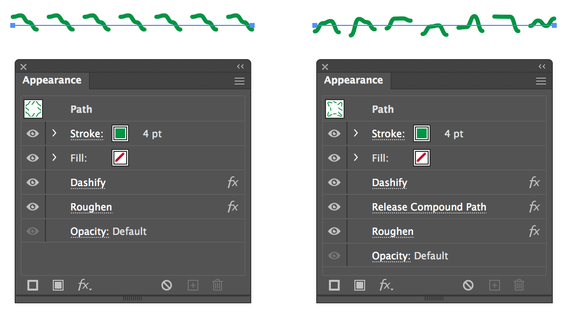
AG Utilities Live Effects - Release Compound Path Example
Illustrator Location:
Retract Handles is an Astute Graphics live effect with one simple function: to retract (remove) the handles of the anchor points in the original art’s paths. An option allows only handles that are shorter than a specified amount to be retracted.
As with most live effects, Retract Handles appears in the main menu, under Effect > AG Utilities. It can also be applied directly from the Appearance panel using the “Add New Effect” button at the bottom of the panel.
Retract Handles Parameters Dialog
After applying the live effect using the menu item (or when clicking on the existing effect in the Appearance panel to edit it), the parameters dialog will appear:
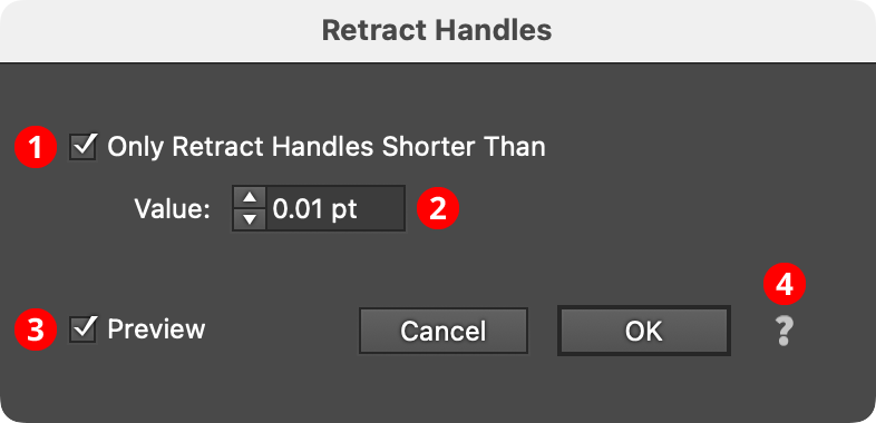
Retract Handles Parameters Dialog
1. Only Retract Handles Shorter Than
When enabled, only the handles in the artwork which are shorter than the specified value are retracted. This can be useful for removing very tiny handles that are generated by a previous live effect in the Appearance stack, such as an Outline Path or PathFinder effect, from keeping subsequent effects, such as AG Corners, from working properly.
2. Value
The length value above which handles will be preserved.
When its Only Retract Handles Shorter Than preference is turned off (the default), the Retract Handles effect ensures that all segments in the paths to which it is applied become straight:
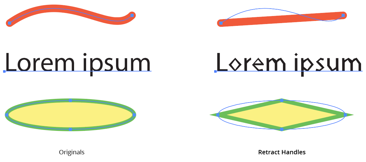
AG Utilities Live Effects - Retract Handles Live Effect
Illustrator Location:
Illustrator Main Menu > Effect > AG Utilities > ...
Reverse Path Direction is an Astute Graphics live effect with one simple function: to reverse the directions of all paths. It has no parameters.
As with most live effects, Reverse Path Direction appears in the main menu, under Effect > AG Utilities. It can also be applied directly from the Appearance panel using the “Add New Effect” button at the bottom of the panel.
For paths that are not subsequently brushed, have arrowheads, or are affected by another live effect that depends on path direction (such as Make Shape), Reverse Path Direction will generally not show any visible changes.
Illustrator Location:
Illustrator Main Menu > Effect > AG Utilities > ...
Segment Removal is an Astute Graphics live effect that removes segments from the paths in the artwork to which it is applied, based on criteria such as their length, handle status, or index. When segments are removed, the path is split into multiple paths (unless the segments are contiguous in a closed path, in which case the path becomes an open path).
As with most live effects, Segment Removal appears in the main menu, under Effect > AG Utilities. It can also be applied directly from the Appearance panel using the “Add New Effect” button at the bottom of the panel.
Segment Removal Parameters Dialog
After applying the live effect using the menu item (or when clicking on the existing effect in the Appearance panel to edit it), the parameters dialog will appear:

Segment Removal Parameters Dialog
1. Criteria Popup
By default, segments will be removed only if they match all of the enabled options (the first four checkboxes below). However you can change this to When They Match Any Enabled Options, Unless They Match All Enabled Options, or Unless They Match Any Enabled Options.
2. Length
Segments match when they have a length (as measured along the path) from the minimum to the maximum values specified.
3. At Least One Handle
When set to Yes, segments match if they have one or two handles; when set to No, segments match if they have no handles (thus are straight).
4. Index
Segments match if their index matches the specified indices. Segments are assigned indices starting at zero, increasing in the order in which they are encountered within the live effect across multiple paths or subpaths. The default type of index match is Odd, i.e. 1, 3, 5, 7, etc. Other options are First, Last, First or Last, Even, and Pattern. Pattern type creates a repeating pattern of matching indices based on the three subsequent parameters.
5. Initial Skip
For Pattern index matching, the initial number of indices to skip over.
6. Match
For Pattern index matching, the number of indices to match after skipping some.
7. Skip
For Pattern index matching, the number of indices to skip over after matching some.
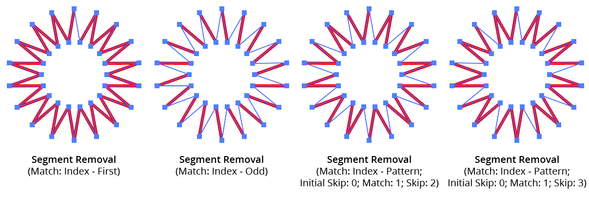
AG Utilities Live Effects - Segment Removal Pattern
8. Randomize
Allows randomization of the removal.
9. Seed
Each random seed number leads to a different sequence of random values. Clicking the button picks a new seed, thereby changing the look of the artwork. To view or specify the seed number directly, Option/Alt-click the button. This lets you recreate a previously-generated look.
10. Retention Probability
The probability that a segment that would normally be removed under the previous criteria will instead be retained.
11. Keep Same Geometry Paths Together
When the Segment Removal effect is positioned under an artwork’s strokes and fills in the Appearance panel, the stroked and filled paths are passed to it separately, and their segments would therefore normally be randomly affected independently, leading to some paths having different segments removed when Randomize is enabled. Sometimes this can be solved by simply moving the Segment Removal effect above them in the Appearance panel, but depending on the other effects that are present, this may not always be possible. In that case, enabling this setting allows paths with the exact same underlying geometry (such as fills and strokes of the same path) have the same segments removed or retained.
12. Preview
As with all live effects, when enabled, changing a parameter will immediately update the artwork while the dialog is still open.
13. Help Button
Opens the help documentation in the Astute Manager. If this does not automatically appear, please ensure your Astute Manager is running first.
Illustrator Location:
Illustrator Main Menu > Effect > AG Utilities > ...
Smart Remove Points is an Astute Graphics live effect that removes anchor points from a path (like the Point Removal effect) but while trying to maintain the geometry of the path. This is achieved by adjusting the lengths (but not angles) of the handles on either side of the removed points.
As with most live effects, Smart Remove Points appears in the main menu, under Effect > AG Utilities. It can also be applied directly from the Appearance panel using the “Add New Effect” button at the bottom of the panel.
Smart Remove Points Parameters Dialog
After applying the live effect using the menu item (or when clicking on the existing effect in the Appearance panel to edit it), the parameters dialog will appear:

Smart Remove Points Parameters Dialog
1. Tolerance
Specifies how much the geometry of the path can change when removing a point. The value can range between 0 and 200, with a default of 10. Low values remove fewer points (prioritizing the path’s geometry) while high values remove more points (at the likely cost of some distortion).
2. Protect Sharp Corners
When enabled, corner points along the path where the path angle changes by more than 6° are never removed, regardless of the tolerance setting. This allows simplifying smooth sections of a path by using a large tolerance without having to worry that sharp corners will be lost.
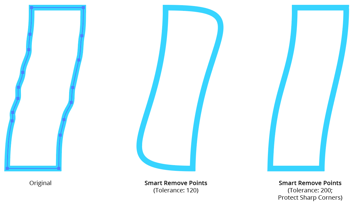
AG Utilities Live Effects - Smart Remove Points Example
3. Preview
As with all live effects, when enabled, changing a parameter will immediately update the artwork while the dialog is still open.
4. Help Button
Opens the help documentation in the Astute Manager. If this does not automatically appear, please ensure your Astute Manager is running first.
Illustrator Location:
Split Path to Segments is an Astute Graphics live effect that breaks a path at its anchor points into multiple segments. Paths can be split at corner points, sharp points, or all points.
As with most live effects, Split Path to Segments appears in the main menu, under Effect > AG Utilities. It can also be applied directly from the Appearance panel using the “Add New Effect” button at the bottom of the panel.
Split Path to Segments Parameters Dialog
After applying the live effect using the menu item (or when clicking on the existing effect in the Appearance panel to edit it), the parameters dialog will appear:
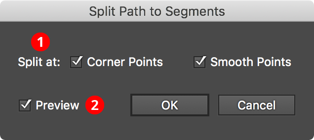
Split Path to Segments Parameters Dialog
1. Split At
Specifies which types of anchor points at which splits should occur: corner, smooth, or both.
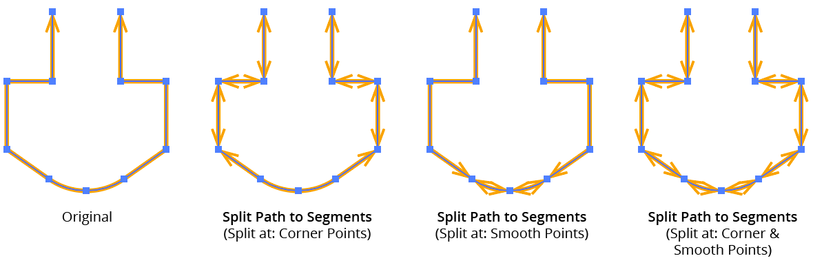
AG Utilities Live Effects - Split Path to Segments Examples
2. Filter By Index
When enabled, each anchor point’s index (starting with zero on each path) is used to determine whether the path will be split at that point. Filter by Index has seven different methods, as follows:
a. First: Each path will be split at the first n points, where n is the specified value.

Split Path to Segments Filter by Index First Controls
b. Last: Each path will be split at the last n points, where n is the specified value.

Split Path to Segments Filter by Index Last Controls
c. First or Last: Only the first and last points will be used as split points.
d. Odd: Only points with an odd index (1, 3, 5, 7...) will be used as split points.
e. Even: Only points with an even index (0, 2, 4, 6...) will be used as split points.
f. Pattern: Creates a repeating pattern of matching indices based on the three pattern parameters.

Split Path to Segments Filter by Index Pattern Controls
Initial Skip specifies the number of indices to skip over at the start (the path will not be split at points with these indices). Then, Match specified the number of indices that will match and therefore cause splits. Finally, Skip specifies the number of indices to skip over following the matching indices. When the total of the values in the three parameters is less than the number of anchor points, the pattern repeats, using the Match and Skip values in alternation.
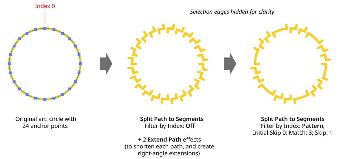
Split Path to Segments Filter by Index - Pattern
g. Randomly: At each anchor point, the path has the specified random chance (from 0% to 100%) of being split. Clicking the Seed button picks a new random seed, thereby changing the look of the artwork. To view or specify the seed number directly,
Option/Alt-clickthe button. This lets you recreate a previously-generated look.

Split Path to Segments Filter by Index Randomly Controls
3. Preview
As with all live effects, when enabled, changing a parameter will immediately update the artwork while the dialog is still open.
3. Help Button
Opens the help documentation in the Astute Manager. If this does not automatically appear, please ensure your Astute Manager is running first.
Illustrator Location:
Illustrator Main Menu > Effect > AG Utilities > ...
Stroke Attributes is an Astute Graphics live effect that allows changing a path’s stroke parameters (weight, end caps, and corner joins). It also allows forcing a stroke onto a fill-only path, and (optionally) removing that fill.
As with most live effects, Stroke Attributes appears in the main menu, under Effect > AG Utilities. It can also be applied directly from the Appearance panel using the “Add New Effect” button at the bottom of the panel.
Stroke Attributes Parameters Dialog
After applying the live effect using the menu item (or when clicking on the existing effect in the Appearance panel to edit it), the parameters dialog will appear:

Stroke Attributes Parameters Dialog
1. Alter Weight
When enabled, the stroke weight of the path(s) will be changed.
2. Base Value Mode
Specifies what to use for the base value of the stroke weight, which may be subsequently modified by the limit values or through randomization:
Set Absolute: The default; the stroke weight will be set to the specified value.
Set Relative to Path Length: The stroke weight will be set to the length of the path times the specified factor. The default factor is 1%, meaning a path with a length of 120 pt would be given a stroke weight of 1.2 pt.
Set Relative to Original: The stroke weight will be set to the original stroke weight times the specified factor. The default factor is 200%, which doubles the existing stroke weight.
Use Original: Does not change the base weight.
3. Weight Value
For Set Absolute mode, specifies the base weight of the stroke. For Set Relative to Path Length mode, specifies the factor (as a percentage) by which the path’s length is multiplied to get the base weight. For Set Relative to Original mode, specifies the factor (as a percentage) by which the original stroke weight is multiplied to get the base weight.
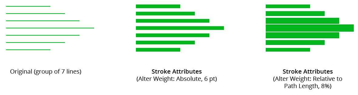
AG Utilities Live Effects - Stroke Attributes Example
4. Limit, Minimum Value
Any base weights smaller than this will be changed to this value.
5. Limit, Maximum Value
Any base weights larger than this will be changed to this value.
6. Alter End Caps
When enabled, the end cap type of the stroke is changed to the specified type.
7. End Cap Type
As per the native stroke panel, the type of end cap to use: Butt, Round, or Projecting.
8. Alter Corner Joins
When enabled, the corner join type of the stroke is changed to the specified type.
9. Corner Join Type
As per the native stroke panel, the type of corner join to use: Miter, Round, or Bevel.
10. Miter Limit
For Miter type joins, per the native stroke panel, the miter limit to use.
11. Randomize
Allows randomization of the final stroke weight. This option is only available when Alter Weight is enabled.
12. Distribution Curves
Specifies either a linear distribution in random values (all values in the range are equally likely to be chosen) or a Gaussian distribution (central values in the range are more likely to be chosen).
13. Seed
Each random seed number leads to a different sequence of random values. Clicking the button picks a new seed, thereby changing the look of the artwork. To view or specify the seed number directly, Option/Alt-click the button. This lets you recreate a previously-generated look.
14. Weight Variation
Specifies the maximum amount of variation in the final stroke weight. For example, if the weight is set to 20 pt, then a variation value of 25% would produce weights that vary by as much as 20pt × 25% = 5 pt, that is, between 15 pt and 20 pt; a variation value of 90% would produce weights between 2 pt and 20 pt.
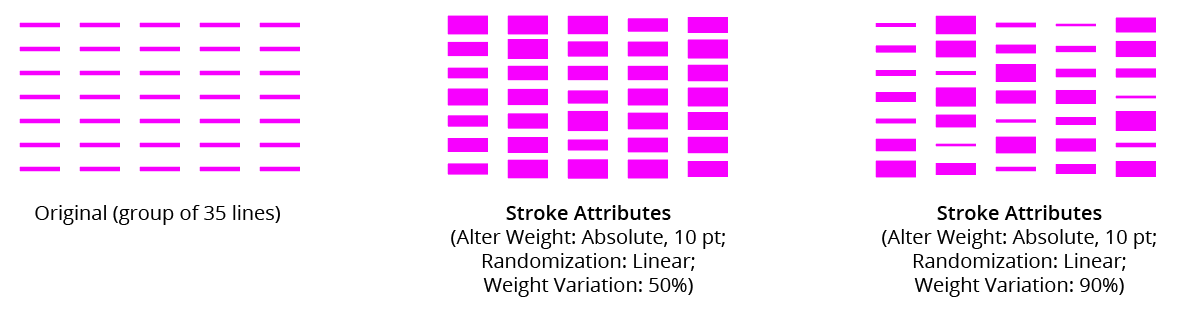
AG Utilities Live Effects - Stroke Attributes Randomization Examples
15. Force Stroke On Fill-Only Paths
When enabled, a stroke will be added to any paths which are fill-only, if at least one attribute (weight, caps, or joins) is specified. For non-specified attributes, default values will be used. The color of the stroke will be the same as the fill color.
16. And Remove Fill
When enabled, the fill of the path will be removed when the new stroke is added.
17. Preview
As with all live effects, when enabled, changing a parameter will immediately update the artwork while the dialog is still open.
18. Help Button
Opens the help documentation in the Astute Manager. If this does not automatically appear, please ensure your Astute Manager is running first.