Overview
AstuteBuddy Panel
Autosaviour Overview
Snap to Collisions Tool
DirectPrefs Overview
Dynamic Sketch
InkFlow
InkQuest Separations Panel
InkScribe
MirrorMe
Phantasm Controls
Reform
Stylism
Texture
VectorFirstAid Panel
PathScribe
Width Stamp
Super Marquee Tool
Randomino Panel
Phantasm Panel
Width Selector
AG Trim and Join Tool
Space Fill
Curves
Opacity Brush
Reprofile
Rotate at Collision Tool
Dynamic Shapes
Width Gradient
Texture Brush
Width Brush Tool
AG Block Shadow
Dynamic Corners
Reform Text
Width Eraser Tool
Optimize and Vary Width Markers
AG Offset
Extend Path Tool
Gradiator
Reposition Point Tool
Gradient Forge
![]() PathScribe
PathScribe
 Reform
 Stylism Tool
 Randomino Panel
 Width Selector
 Space Fill
![]() PathScribe Panel
PathScribe Panel
 Reprofile
 Dynamic Shapes
 Dynamic Corners
 Reform Text
 Dynamic Measure
 AG Layer Comps
 Extend Path Tool
![]() Smart Remove Brush Tool
Smart Remove Brush Tool
 Gradiator
 Reposition Point Tool
 Gradient Forge
Illustrator Location:
Illustrator Main Menu > Window > Astute Graphics > AstuteBuddy
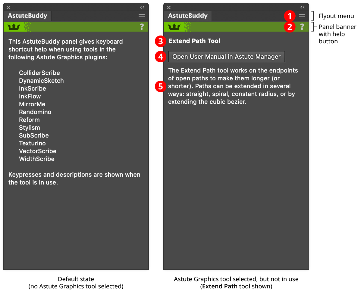
The menu item to show and hide the AstuteBuddy panel can be found in the main menu under Window > Astute Graphics > AstuteBuddy. But by default, the AstuteBuddy panel will automatically be shown when an Astute Graphics tool is selected and automatically hidden when any other tool is selected. This behavior can be customized using the AstuteBuddy preferences.
AstuteBuddy Panel
1. Flyout menu
Provides a single menu item, which opens the preferences dialog (see AstuteBuddy Preferences).
2. Panel banner
The AstuteBuddy panel banner has a help button on the right which opens the help documentation in the Astute Manager. If this does not automatically appear, please ensure your Astute Manager is running first.
3. Tool Name
The name of the currently-selected Astute Graphics tool, for example “Extend Path tool.”
4. User Manual Button
Clicking the button opens the documentation for the current tool in the Astute Manager, which provides more extensive descriptions that can be fit on the AstuteBuddy panel. This button can be hidden using the preference Show User Manual Button.
5. Tool Overview
A brief, high-level overview of the currently-selected Astute Graphics tool. For example, when the Extend Path tool is selected, it displays “The Extend Path tool works on the endpoints of open paths to make them longer (or shorter). Paths can be extended in several ways: straight, spiral, constant radius, or by extending the cubic bezier.”
Illustrator Location:
Illustrator Main Menu > Window > Astute Graphics > Autosaviour
Autosaviour is a free Astute Graphics plugin that automatically saves (or just reminds) and/or creates backup copies of your documents (when saved locally, i.e., not to the Creative Cloud). Its panel displays the time of last save, the time remaining until the next autosave/reminder, and access to settings such as the autosave interval, backup location, and backup naming scheme.
Illustrator Location:
Advanced Toolbar > Selection Stack > Snap to Collisions Tool
Snap To Collisions is an Astute Graphics tool for Adobe Illustrator that supplements Smart Guides by enabling you to place a path next to one or more paths such that the paths precisely touch or have a predetermined space between them. An option to automatically add anchor points to the paths at their touching spots is also provided. Snap To Collisions is part of the ColliderScribe plugin.
Tool Location and Cursor Appearance
The Snap To Collisions tool appears in Illustrator’s main toolbar (which must be in Advanced mode: View > Toolbars > Advanced) stacked under the native Selection tool along with ColliderScribe’s other tools. As with other stacked tools, click and hold on the top tool icon to display the tools stacked under it.
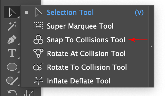
Snap to Collisions Tool Location
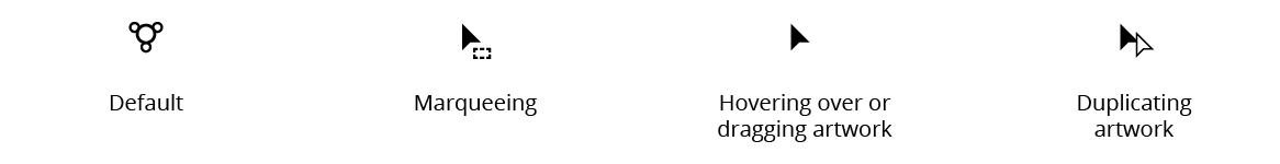
The Snap To Collisions tool’s cursor changes depending on what the tool is currently doing:
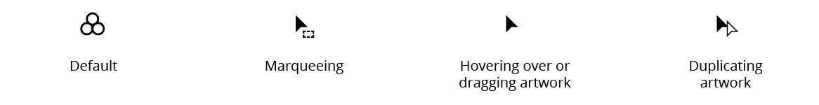
Snap to Collisions Tool Cursors
Additionally, a small dot will appear next to the last two cursors when the Add Points to Paths at Collisions preference is enabled.
Illustrator Location:
Illustrator Main Menu > Window > Astute Graphics > DirectPrefs
DirectPrefs is a free Astute Graphics panel for Adobe Illustrator that allows the visualization and direct adjustment of several of the most-used preferences and settings — including the general constrain angle, keyboard increment value, guide status, and grid status — without having to go to the General Preferences dialog or remember menu command shortcuts. It also provides a function that allows you to draw shapes or move art objects with the arrow keys in the normal directions, regardless of canvas rotation. Finally, it includes the ability to rotate the document view forward and backward step-wise, the ability to change the opacity of non-isolated art (when in Illustrator’s isolation mode), and several Astute-specific preferences, including whether to auto-open the panels associated with Astute Graphics tools.
Illustrator Location:
Illustrator Main Menu > Window > Astute Graphics > Dynamic Sketch
Dynamic Sketch is an Astute Graphics tool for Adobe Illustrator that is similar to the native Pencil tool, but with many more features. With an associated panel for controlling various functions and parameters, Dynamic Sketch can use a pulled-cursor for smoother curves; create paths using variable smoothness and accuracy (which can be edited even after the sketch path is completed); average multiple sketch paths together; intelligently join paths, trimming off excess sections; control the width of the path using cursor speed or stylus pressure; and more.
Illustrator Location:
Illustrator Main Menu > Window > Astute Graphics > InkFlow
InkFlow is an Astute Graphics tool and panel for Adobe Illustrator which allows you to draw calligraphic- style strokes with thinning and ink effects. It is an improvement on the native calligraphic brush, and allows for multiple preset pens, user-calibrated response, pen stabilization, and more realistic strokes. InkFlow strokes are implemented as live effects, which means that they can have their parameters changed after they have been drawn.
InkFlow is generally most useful for lettering, or for sketch-style line drawings. However, since it is a live effect, it can also be applied to paths such as geometric shapes.
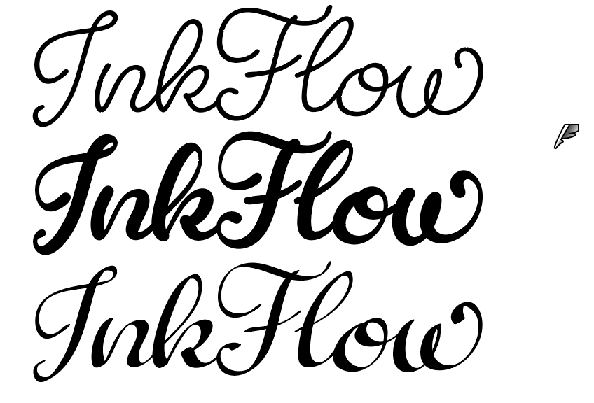
InkFlow Overview
Illustrator Location:
Please note: InkQuest has been deprecated, please find out more in our dedicated support article: https://astutegraphics.com/support/compatibility/inkquest-plugin-end-of-life
Illustrator Location:
Illustrator Main Menu > Window > Astute Graphics > InkScribe
InkScribe is an Astute Graphics tool for Adobe Illustrator that is similar to the native Pen tool, but with additional capabilities, combining aspects of the Direct Select tool and Anchor Point tool. With an associated panel for controlling various functions, InkScribe can not only draw paths but can edit them — adjusting path segments and moving handles and anchor points — without having to switch to another tool or even press a modifier key. Additional features include drawing with constrained length values, creating connector points, and Smart Removing anchor points.
Illustrator Location:
Illustrator Main Menu > Window > Astute Graphics > MirrorMe
MirrorMe is a free Astute Graphics tool and panel for Adobe Illustrator that allows you to create and edit symmetrical art. Symmetry axes can be applied to selected art as a one-time operation, or as persistent axes on a layer, which can continually mirror anything on that layer drawn into the active sector. Paths which cross a symmetry axis can be automatically trimmed and joined to the mirrored portions. Layer axes are saved and recalled with the document.
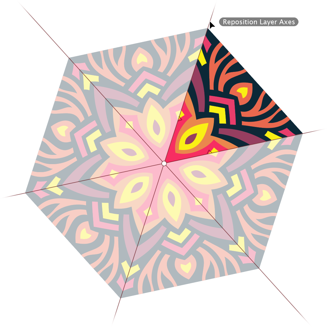
MirrorMe Example
Illustrator Location:
Illustrator Main Menu > Window > Astute Graphics > Phantasm
Load/Save Buttons
The following effects allow loading and saving of adjustment parameters into a Photoshop-compatible file:
Curves (curve mode): Photoshop curves file (.ACV)
Curves (freehand mode): Photoshop curves map file (.AMP)
Exposure: Photoshop exposure file (.EAP)
Hue/Saturation: Photoshop HSL file (.AHU)
Levels: Photoshop levels file (.ALV)
Duotone: Photoshop duotone file (.ADO)
Clicking on either the Load or Save buttons will open the standard operating system’s file load/save dialog. To maintain Photoshop compatibility, these settings files do not store the parameters in the lower Options section. Instead, these are loaded and saved separately through the Settings Manager menu (see Phantasm: Common Options (Basic)).
Cancel/Reset Button
Holding down the Option/Alt key will temporarily change the Cancel button into a Reset button, which, when clicked, will reset all of the effect’s parameters to their default settings (this does not include the Options, which may be reset to their defaults using the Settings Manager menu).
Preview Checkbox
All Phantasm live effect/filter dialogs feature a Preview button. When enabled, artwork is immediately updated to reflect changes to any effect parameter. As per Adobe’s guidelines for live effects, if Preview is subsequently turned off, no further changes take place to preview the adjustments, but the last previewed state remains visible. The Preview setting is maintained across uses of the effect.
Illustrator Location:
Illustrator Main Menu > Window > Astute Graphics > Reform
Reform is a plugin for Adobe Illustrator which lets you “re-form”, or reshape, an entire path or a portion of a path without having to individually adjust or even worry about the individual anchor points and bezier handles that make up the path. It consists of a tool and an associated panel.
Reform gives the best results when it is used to make subtle changes to paths. Very large offsets will often produce unpredictable results, especially at corners.
After installing the plugin, the Reform tool will show up in Illustrator's main toolbar (which must be in Advanced mode: Window > Toolbars > Advanced):
Reform Toolbox Icon
Click on the Reform tool in the toolbar to select it. If you use the tool frequently, you may want to assign it a keyboard shortcut key through Illustrator's Keyboard Shortcuts dialog (Edit > Keyboard Shortcuts...). You can also click on the Reform panel to select the Reform tool.
If you have Astute Graphics' DirectPrefs plugin installed, and its Auto Open Astute Graphics Panels preference enabled (enabled by default), then selecting the Reform tool will automatically show the Reform panel. Otherwise, if the panel is not visible, choose Window > Astute Graphics > Reform. While the Reform panel is not required in order to use the tool and reshape paths, it does contain various settings, options and commands that can only be accessed there.
For now, with a document open, simply hover the Reform tool's cursor over a basic open path. The path (or a section of it) will highlight (the default color is blue). Press the mouse button down and drag with the tool. You will see a new, red line appear, which is a preview of the reshaped path. How far you drag determines how far the reshaped path bends away from the original.
To finalize the reshape, press the Return or Enter key, or click the Apply button on the Reform panel. The newly-reshaped path remains selected. Alternatively, Option/Alt + Return or Enter, or holding down Option/Alt when clicking the Apply button will create a duplicate of the reshape path, maintaining the original as-is.
Illustrator Location:
Illustrator Main Menu > Window > Astute Graphics > Stylism
Stylism is an Astute Graphics tool and panel for Adobe Illustrator that allows the on-screen adjustment of the parameters of eight common native live effects: Drop Shadow, Feather, Inner Glow, Outer Glow, Transform, Free Distort, Offset Path, and Gaussian Blur. It creates a custom, annotated UI controlled by the Stylism tool that, in conjunction with the panel, allows these effects to be added, removed, and edited graphically, without ever having to use the parameters dialog. Additionally, it includes “Live Effect Explorer,” a dialog which lists information about all the live effects in the selected artwork and allows them to be removed or hidden, even if they have different parameters (“Mixed Appearances”). Stylism is part of the Stylism plugin, which also contains additional live effects, such as AG Block Shadow and AG Offset.
Illustrator Location:
Illustrator Main Menu > Window > Astute Graphics > Texture
Texture is an Astute Graphics live effect for Adobe Illustrator that makes it simple to add one or more raster-based textures to art objects. Each texture’s blending mode, scale, rotation, and position can be specified. Textures can be imported and exported for sharing with other users. The live effect is controlled by both a panel and a tool. Texture is part of the Texturino plugin.
Illustrator Location:
Illustrator Main Menu > Window > Astute Graphics > VectorFirstAid
Menu items to show and hide the VectorFirstAid panel can be found in the main menu under Window > Astute Graphics > VectorFirstAid.
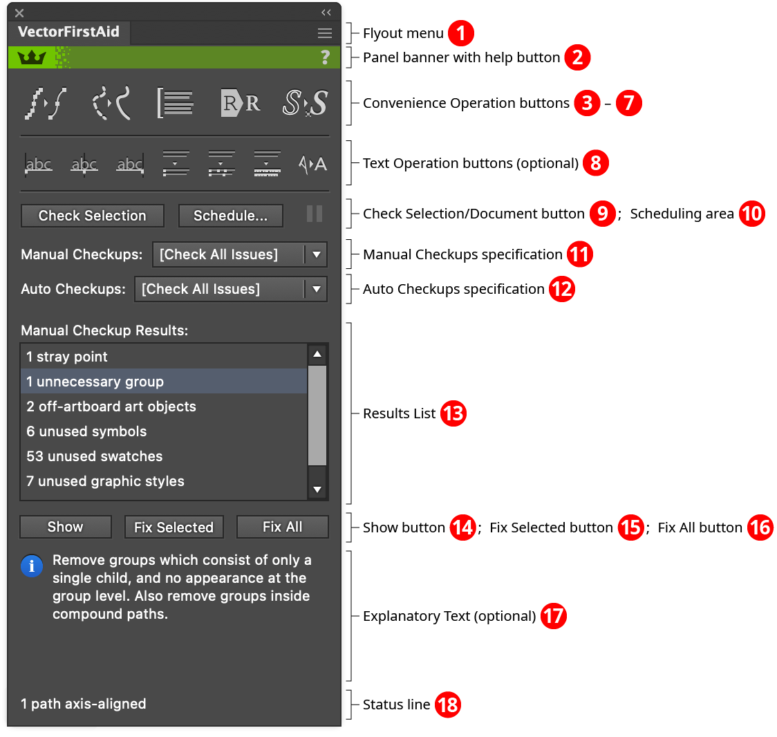
VectorFirstAid Panel
1. Flyout menu
See VectorFirstAid Panel: Flyout Menu.
2. Panel banner
The help button on the right opens the help documentation in the Astute Manager. If this does not automatically appear, please ensure your Astute Manager is running first.
3.4.5.6.7. Convenience Operation Buttons
See VectorFirstAid Panel: Convenience Operation Buttons.
8. Text Operation Buttons
See VectorFirstAid Panel: Text Operation Buttons.
9.10.11.12.13. Checkup Buttons
See VectorFirstAid Panel: Checkup Buttons.
14.15.16. Show and Fix Buttons
See VectorFirstAid Panel: Show and Fix Buttons.
17. Explanatory Text
This section of the panel (which is shown by default but can be hidden if desired using the panel’s flyout menu) gives a short description of the single issue that is selected (highlighted) in the results list section of the panel, as well as the steps that VectorFirstAid would take to fix it.
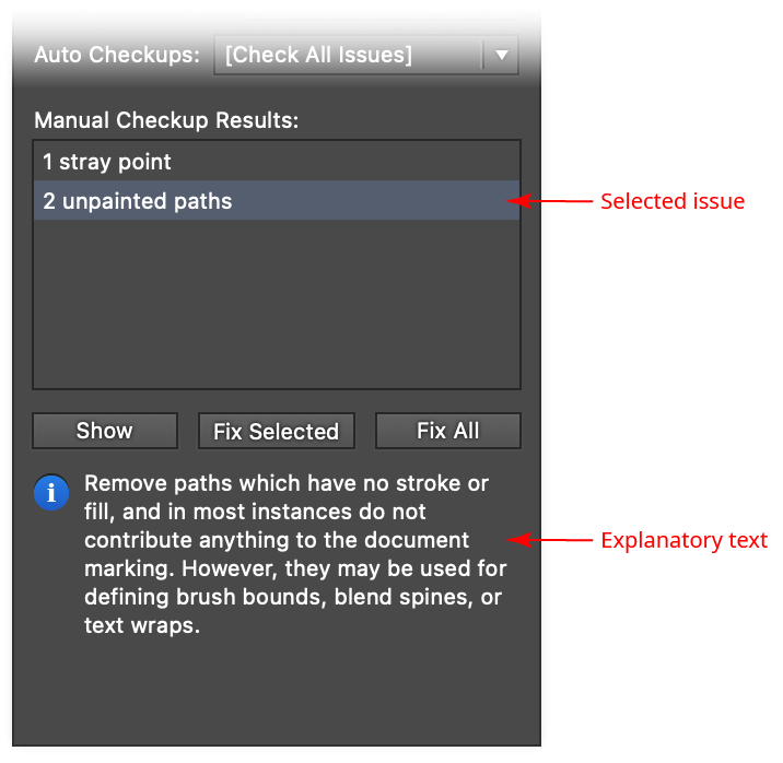
VectorFirstAid Explanatory Text
18. Status Line
Displays status information after issues are fixed, or after any of the convenience operation or text operation buttons are used. For example, it might show “1 redundant point removed” after fixing a redundant point issue, or “No rejoinable paths found in selection” if the Rejoin Paths button was used.
Illustrator Location:
Illustrator Main Menu > Window > Astute Graphics > PathScribe
The PathScribe component of VectorScribe consists of the PathScribe tool and the PathScribe panel. While the tool can be used alone, much of PathScribe’s functionality is accessed through the panel.
This functionality includes the ability to:
Select multiple handles, and collectively move, extend, rotate, or retract them
Extend or retract handles without changing their angles
Copy and paste handles
Edit anchor point positions and handle positions, lengths or angles numerically
Equalize a point’s handles, or the handles on either side of a path segment
Work with connector points (transitions between straight and curved segments)
Use “slow-drag” to gear down cursor movement for extremely precise moves
Remove one or more anchor points while keeping the curve as close to the original as possible Add or move points to a path’s horizontal or vertical tangencies
Add variable numbers of points to path segments
Close multiple paths, retaining endpoint handles or not
Visualize and remove all redundant points on multiple paths
Set, grow, shrink, or invert the current point selection
Illustrator Location:
Illustrator Main Menu > Window > Astute Graphics > Width Stamp
Width Stamp is an Astute Graphics panel for Adobe Illustrator for creating woodcut or intaglio-like effects. It allows you to place a predefined or user-defined pattern of lines (the “contours”) above an art object and then vary the widths of those lines based on the grayscale values of the artwork below them. The look of the Width Stamp object can be fine tuned by adjusting its parameters, such as the transfer function between the art’s grayscale values and stroke width, the fidelity and smoothness, whether the contours use dashes or tapering, and more. The complete parameter set can be saved and instantly recalled later, and a live Width Stamp object can be released back into its component objects at any time. Width Stamp is part of the WidthScribe plugin.

Width Stamp Overview Example
Illustrator Location:
Advanced Toolbar > PathScribe Tool
Overview, Cursor Snapping, and Slow-Drag
PathScribe Tool Location
The PathScribe tool is used to click on or drag direction handles, anchor points, and path segments; it can also be dragged from a blank area of the document as a marquee to select handles or points. When the tool is selected and held over a blank area of the document, the cursor looks like an inverted “V,” similar to the Convert Anchor Point tool, but thicker, so as to distinguish it.
The cursor will change its appearance to give you feedback, depending on several factors: what lies underneath, whether you are dragging or not, and what modifier keys are being held down.
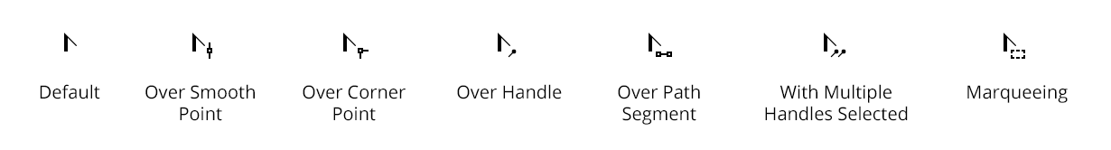
PathScribe Cursors
In addition, by default, PathScribe draws a red ring around the cursor and a text label when it is snapping to an item of interest (handle, anchor point, path segment). This behaviour can be customized or disabled in the tool’s preferences.
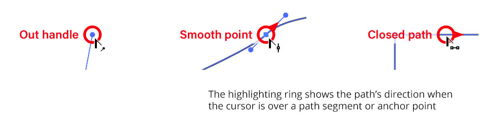
PathScribe Point Handles snapping rings
When Smart Guides are on, PathScribe snaps as usual using the radius value set in Illustrator Preferences > Smart Guides > Snapping Tolerance. When Smart Guides are off, PathScribe snaps using the snapping radius you have set in Illustrator Preferences > Selection & Anchor Display > Selection > Tolerance, plus one pixel.
Making precise adjustments to handle positions with one of the selection tools is often frustrating because you may need to zoom in so far that you can’t see everything you need to. PathScribe offers a feature called “slow-drag” that can help you.
To use slow-drag, hold down the Control key on Mac, or the Ctrl key on Windows (note: the Use Ctrl Key to Toggle Slow-Drag preference must be enabled). The cursor will show a small “S” to remind you that you are slow-dragging. The cursor’s movement will be divided by a value called the slow-drag divider (settable in the preferences). For example, at 100% View, each pixel corresponds to the unit of length of one point. You can normally move a handle, therefore, only in one-point increments at this view. But if you set the slow-drag divider to 10 and move the cursor, each pixel of movement will move the handle by only 0.1 points:
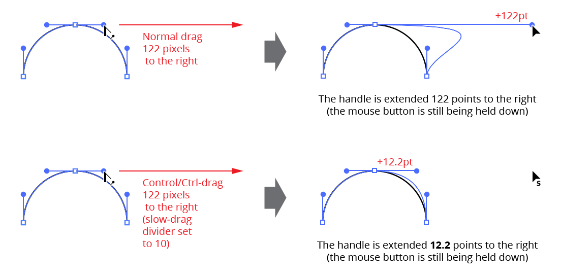
PathScribe slow-drag
Slow-drag can be used when dragging handles (single or multiple), points, and paths, and in combination with the other modifier keys. If Smart Guides were enabled when you started dragging, you can also press the U key to temporarily turn them off.
Illustrator Location:
Advanced Toolbar > Reform Tool
The delimiters can be moved by dragging them. To disable snapping to anchor points, hold down Command/Ctrl while dragging. To quickly move the delimiters so that the entire path is affected by the Reprofile tool, doubleclick either one of them. For an open path, this will move them to the path's endpoints. For a closed path, this will enter “looped mode” (see below). If a delimiter is dragged such that a marker would fall outside of the newly-delimited portion of the path, the marker will be automatically deleted. If a marker is located exactly on a delimiter, then moving the delimiter will also move the marker.
Markers can be moved by dragging them within the delimited reshape extent. To disable snapping to the path's underlying anchor points, hold down Command/Ctrl while dragging. Dragging a marker by its circle annotation will allow you to freely change both its position along the path and its offset; to change only its offset, hold down Shift while dragging.
To change only its position, drag the marker's black line or black square annotation.
To select a single marker, click on its circle annotation.
Multiple markers may be selected by Shift + clicking them or by dragging a marquee over them in the normal manner.
To delete a marker, doubleclick its red square.
To create an additional marker, place the cursor over either the original or virtual reshaped path and click or click-and-drag.
To change a marker from smooth to sharp or vice versa while dragging it, press the X key.
When using the Reprofile tool, Astute Graphics’ AstuteBuddy panel should be kept open to show relevant keypresses.
Illustrator Location:
Advanced Toolbar > Stylism Tool
The center circle control is displayed by all live effects, and can be used in three ways.
1. If multiple objects with supported live effects are selected, only one can be operated on at a time. This targeted object has its annotated controls drawn in red (by default), while the other objects’ controls are drawn in grey. To target a selected object so its live effect may be edited, click its center circle control:
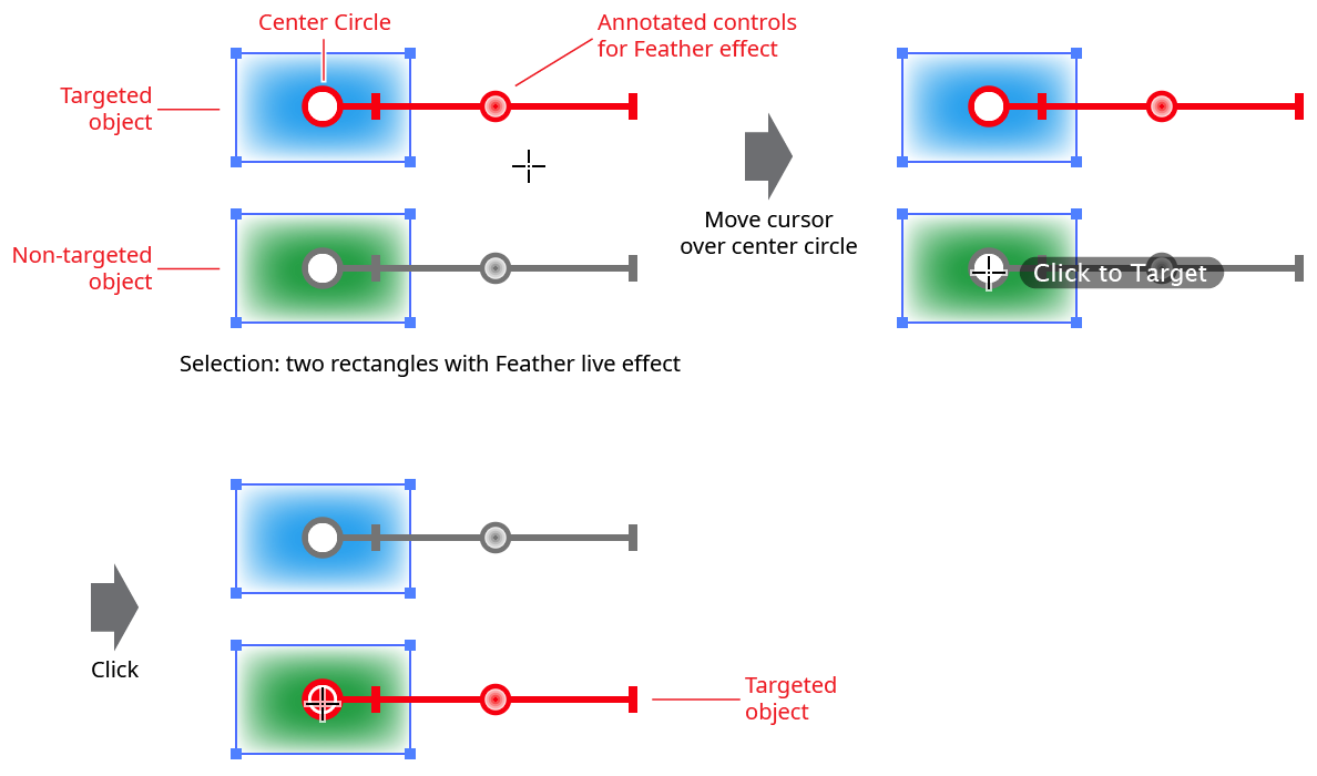
Stylism Click to Target Example
Alternatively, you can simply click or drag the (grey) control of a non-targeted object to target it. However, not all controls may be available for non-targeted objects.
2. Doubleclicking on the center circle control will bring up the live effect’s native parameters dialog for the targeted object, allowing you to edit the live effect in the normal way:
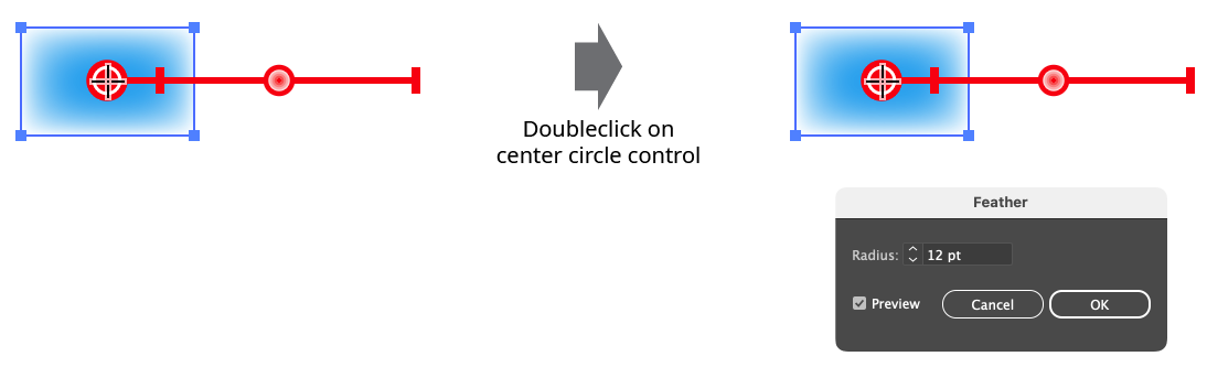
Stylism Opening Native Parameters Dialog
3. When multiple objects with the same live effect are selected, the parameters of some or all of the non-targeted objects may be changed to match those of the targeted object, by syncing them. To do this, drag from the center circle control of the targeted object. A thick, semi-transparent line will follow the cursor. As the cursor is passed over the center circles of the non-targeted objects, the line will remain connecting them, adding them to the sync set and indicating that their live effect parameters will be changed to match the targeted object when the mouse button is released:
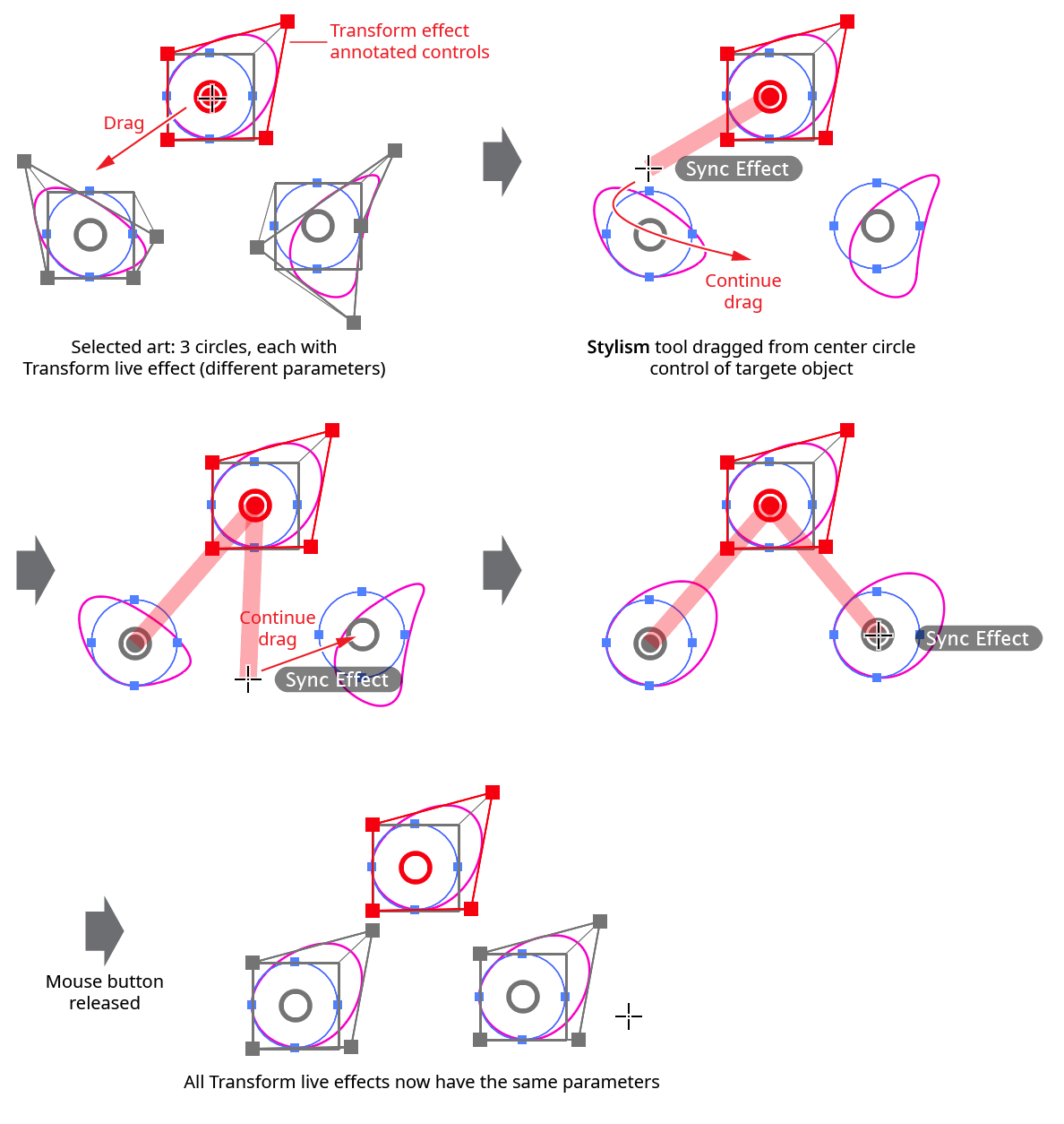
Stylism Syncing Effects
While dragging to sync, there are several keypresses which can be used:
Shift: Instead of adding art to the sync set when the cursor is passed over its center circle, it toggles that state (i.e., if it was set to sync, it will not sync).
Space: Temporarily hides the annotations.
Backspace: Removes the previously-added art (if any) from the sync set.
A: Adds all eligible art to the sync set. If there are many art objects selected, this is much faster than manually dragging the cursor around to add each one individually.
N: Removes all eligible are from the sync set (i.e., clears any sync set selection already made).
Annotated Controls and Common Drag Keypresses
All of the effect’s annotated controls which are dragged, such as slider thumbs, react the same way to several keypresses:
Command/Ctrl: Enables “slow-drag”. When slow-dragging is active, the motion of the cursor is divided by a factor called the slow-drag divider value (specified in the Stylism Preferences dialog), allowing finer control over the movement of the control. For example, if the Slow-Drag Divider is at its default value of 10, and the zoom level is 100%, then moving the cursor by 7 pixels would result in a virtual movement of the control by only 0.7 pixels.
Space: Temporarily hides all of the annotations while the key is held down.
C: Changes the annotation color, cycling through red, blue, magenta, green black, and grey.
Illustrator Location:
Advanced Toolbar > Selection Stack > Super Marquee Tool
Super Marquee is an Astute Graphics tool for Adobe Illustrator used for marquee-selecting objects. It has significant additional functionality over the native Selection and Direct Selection tools. In addition to an enclosing mode, where objects are only selected if they fall entirely within the marquee, Super Marquee offers dynamic highlighting, a repositionable marquee, three additional marquee shapes, Boolean Mode, and alternation/randomization options. Super Marquee is part of the ColliderScribe plugin.
Tool Location and Cursor Appearance
The Super Marquee tool appears in Illustrator’s main toolbar (which must be in Advanced mode: View > Toolbars > Advanced) stacked under the native Selection tool along with ColliderScribe’s other tools. As with other stacked tools, click and hold on the top tool icon to display the tools stacked under it.
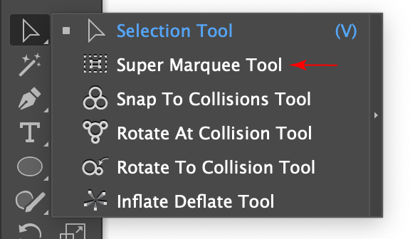
Super Marquee Tool Location
The Super Marquee tool’s cursor changes depending on which mode it is in:

Super Marquee Tool Cursors
Additionally, small badges will be added to the cursor when the tool is in Boolean Mode, to indicate whether the tool is adding to, subtracting from, or intersecting with the selection.
Illustrator Location:
Illustrator Main Menu > Window > Astute Graphics > Randomino
The Randomino panel allows precise randomization of selected artwork with finer control and more options than the Randomini tool. Additionally, it allows you to operate on text characters and to save and recall your favorite randomization settings. The panel will configure itself differently depending on the attribute you are randomizing and whether you are picking random values from a range of values or from a list of discrete values.
The Randomino panel will appear in the main menu under Window > Astute Graphics > Randomino. It is shown here with default settings:
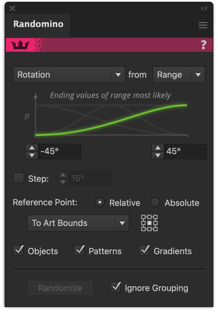
Randomino Default Panel
Illustrator Location:
Illustrator Main Menu > Window > Astute Graphics > Reform
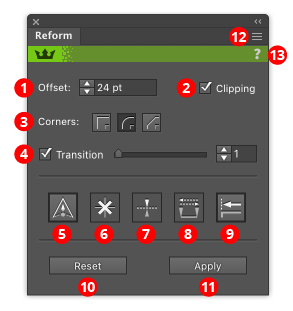
Reform Panel Overview
1. Offset value
Lets you numerically enter the offset value of the selected markers. Note that negative values are allowed, and push the path in the opposite direction from a positive value.
2. Clipping checkbox
Turns on and off clipping. Clipping is useful when the specified offsets cause the path to cross over itself, by removing those loops:
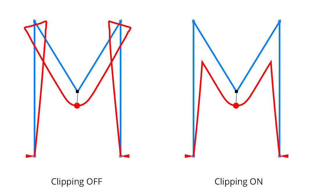
Reform Clipping Paths
3. Corners buttons
When reshaping a path with an abrupt change in path direction, the corner type specifies how the reshaped path bends around the original corner:
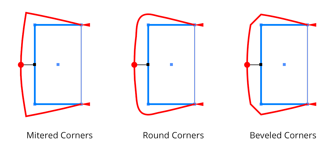
Reform Corner Types
4. Transition checkbox/value
Controls the smoothness of the transition between the original path and its reshaped portion (Off, or values of 1-10):
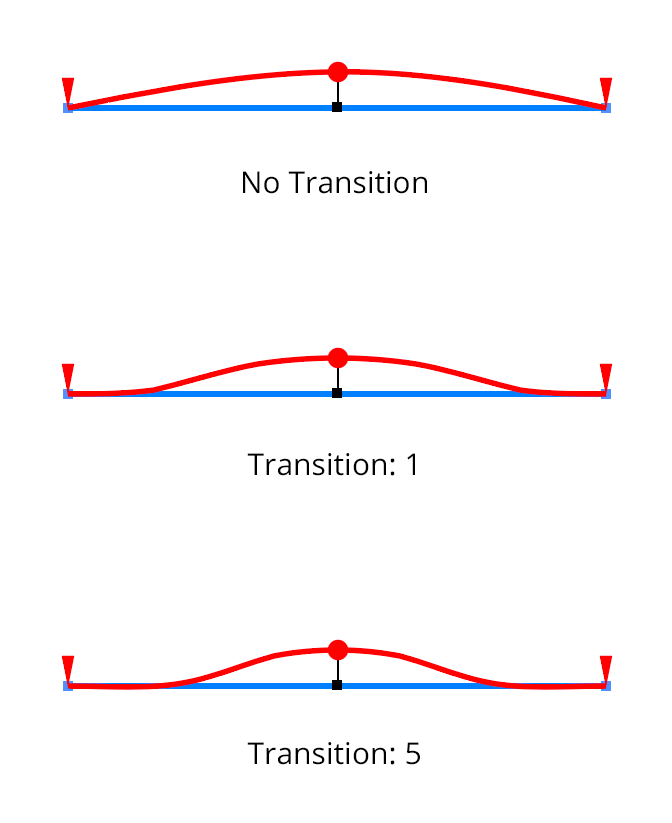
Reform Transition Overview
5. Sharp marker button
Toggles the selected markers between smooth and sharp (see above for explanation of different types). It also controls the type of any newly created markers.
6. Delete marker button
Removes all selected markers.
7. Mirror offset button
Changes the direction of the offset of all selected markers. This is the same as changing the sign of the offset value.
8. Swap marker direction button
Changes the position of all markers (selected or not) along the reshape extent. If, for example, a marker is located 1/5 of the way from the start to the end delimiter, swapping the direction will change it to be 1/5 of the way from the end to the start delimiter. Offset values are not changed.
9. Smart Joining button
10. Reset button
Cancels the reshape operation. The path remains unmodified. This can also be achieved by pressing the Esc key when the cursor is in motion.
11. Apply button
Finalizes the path reshape. This can also be achieved by pressing Return or Enter.
12. Flyout menu
Provides access to the preferences dialog, and allows saving and recalling of profiles (see below).
13. Panel banner
The help button on the right opens the help documentation in the Astute Manager. If this does not automatically appear, please ensure your Astute Manager is running first.
Click on the other area of the color bar to activate the Reform tool. This is a quick method of locating the tool within the default Advanced toolbar or a custom toolbar.
Illustrator Location:
Illustrator Main Menu > Window > Astute Graphics > Phantasm
Menu items to show and hide the Phantasm panel can be found in the main menu under Window > Astute Graphics > Phantasm. Be default, all of Phantasm’s effects are shown on the panel, but, except for the top four effects (Levels, Curves, Duotone, and Halftone), they can be individually hidden or shown through the flyout menu. The lower effects include controls such as sliders which can be used to instantly adjust artwork without having to use a parameters dialog. However, for Brightness/Contrast, Hue/Saturation, and Exposure, not all parameters are adjustable directly on the panel. If multiple copies of an effect are present in the targeted artwork, only the parameters from the last copy are reflected on the panel.
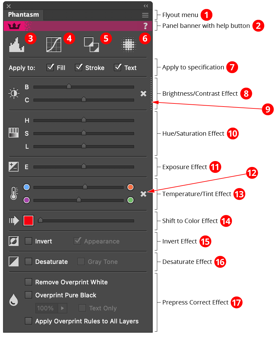
Phantasm Panel Overview
1. Flyout menu
See Phantasm Panel: Flyout Menu.
2. Panel banner
The help button on the right opens the help documentation in the Astute Manager. If this does not automatically appear, please ensure your Astute Manager is running first.
3. Levels Effect
Clicking the icon will apply the Levels effect to the targeted artwork (if not already applied) and then open its parameters dialog. Option/Alt-clicking the icon will apply Levels as a filter instead. Read more about Levels.
4. Curves Effect
Clicking the icon will apply the Curves effect to the targeted artwork (if not already applied) and then open its parameters dialog. Option/Alt-clicking the icon will apply Curves as a filter instead. Read more about Curves.
5. Duotone Effect
Clicking the icon will apply the Duotone effect to the targeted artwork (if not already applied) and then open its parameters dialog. Option/Alt-clicking the icon will apply Duotone as a filter instead. Read more about Duotone.
6. Halftone Effect
Clicking the icon will apply the Halftone effect to the targeted artwork (if not already applied) and then open its parameters dialog. Option/Alt-clicking the icon will apply Halftone as a filter instead. Read more about Halftone.
7. Apply to Specification
The checkboxes reflect the “Apply to:” settings found in the Basic options of each applied effect, except for Duotone, Halftone, and Prepress Correct. See Phantasm: Common Options (Basic).
8. Brightness/Contrast Effect
Clicking the icon will apply the Brightness/Contrast effect to the targeted art (if not already applied) and then open its parameters dialog. Option/Alt-clicking the icon will apply Brightness/Contrast as a filter instead. The sliders may also be used to instantly apply the effect (if not already applied) and adjust the Brightness and Contrast parameters qualitatively.
9. Hidden Effect Indicator
When a dotted line appears at the right edge of an effect (the four top effects share a single indicator), it means that the effect has been applied to the targeted artwork but has been hidden using the Appearance panel. Clicking the indicator will make the effect visible.
10. Hue/Saturation Effect
Clicking the icon will apply the Hue/Saturation effect to the targeted artwork (if not already applied) and then open its parameters dialog. Option/Alt-clicking the icon will apply Hue/Saturation as a filter instead. The sliders may also be used to instantly apply the effect (if not already applied) and adjust the Hue, Saturation and Lightness parameters of the Master channel qualitatively. To use Colorize mode or adjust channels other than Master, open the full parameters dialog by clicking the icon.
11. Exposure Effect
Clicking the icon will apply the Exposure effect to the targeted artwork (if not already applied) and then open its parameters dialog. Option/Alt-clicking the icon will apply Exposure as a filter instead. The sliders may also be used to instantly apply the effect (if not already applied) and adjust the Exposure parameter qualitatively. To adjust the Offset or Gamma parameters, open the full parameters dialog by clicking the icon.
12. Remove Effect Button
Each effect that has been applied to at least one targeted object will display this button, which may be clicked to remove the effect from all targeted objects.
13. Temperature/Tint Effect
Clicking the icon will apply the Temperature/Tint effect to the targeted art (if not already applied) and then open its parameters dialog. Option/Alt-clicking the icon will apply Temperature/Tint as a filter instead. The sliders may also be used to instantly apply the effect (if not already applied) and adjust the Temperature and Tint parameters qualitatively.
14. Shift to Color Effect
Clicking the icon will apply the Shift to Color effect to the targeted art (if not already applied) and then open its parameters dialog. Option/Alt-clicking the icon will apply Shift to Color as a filter instead. The color chip may be clicked to pick a color, and the slider may also be used to instantly apply the effect (if not already applied) and adjust the Shift parameter qualitatively.
15. Invert Effect
Clicking the icon will apply the Invert effect to the targeted art (if not already applied) and then open its parameters dialog. Option/Alt-clicking the icon will apply Invert as a filter instead. The checkbox may be used to instantly apply the effect (if not already applied) and the Invert Appearance parameter may be toggled with the second checkbox.
16. Desaturate
Clicking the icon will apply the Desaturate effect to the targeted art (if not already applied) and then open its parameters dialog. Option/Alt-clicking the icon will apply Desaturate as a filter instead. The checkbox may be used to instantly apply the effect (if not already applied) and the Gray Tone parameter may be toggled with the second checkbox.
17. Prepress Correct Effect
Clicking the icon will apply the Prepress Correct effect to the targeted art (if not already applied) and then open its parameters dialog. Option/Alt-clicking the icon will apply Prepress Correct as a filter instead. The Remove Overprint White and Overprint Pure Black checkboxes may be used to instantly apply the effect (if not already applied) and turn on those options. When the Apply Overprint Rules to All Layers checkbox is enabled, the Prepress Correct effect is immediately applied to all layers in the document, and will be added to any new layers that are subsequently created.
Illustrator Location:
Illustrator Main Menu > Window > Astute Graphics > Randomino
Most kinds of randomizable attributes are controlled using numerical parameters. Opacity is one such attribute, and the panel, when set to Opacity kind, demonstrates controls common to most of the other kinds.
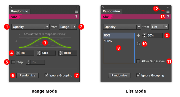
Randomino Panel Common Panel Callouts
1. Kind popup menu
Chooses the attribute to be randomized, from among: Color, Live Effects, Movement, Opacity, Rotation, Scaling, Stacking Order, and Stroke Weight.
2. Range/List popup menu
Selects which method of choosing values to use. In Range mode, values are randomly chosen from anywhere within a continuous range of values (as shown, 0% to 100%). In List mode, values are randomly chosen from among a list of discrete values (as shown, 50%, and 100%).
3. Distribution curve (range mode only)
Selects (among four models) how values are randomly chosen from a range. The green curve represents the probability of choosing a value from a given location in the range, with zero being the bottom x-axis.
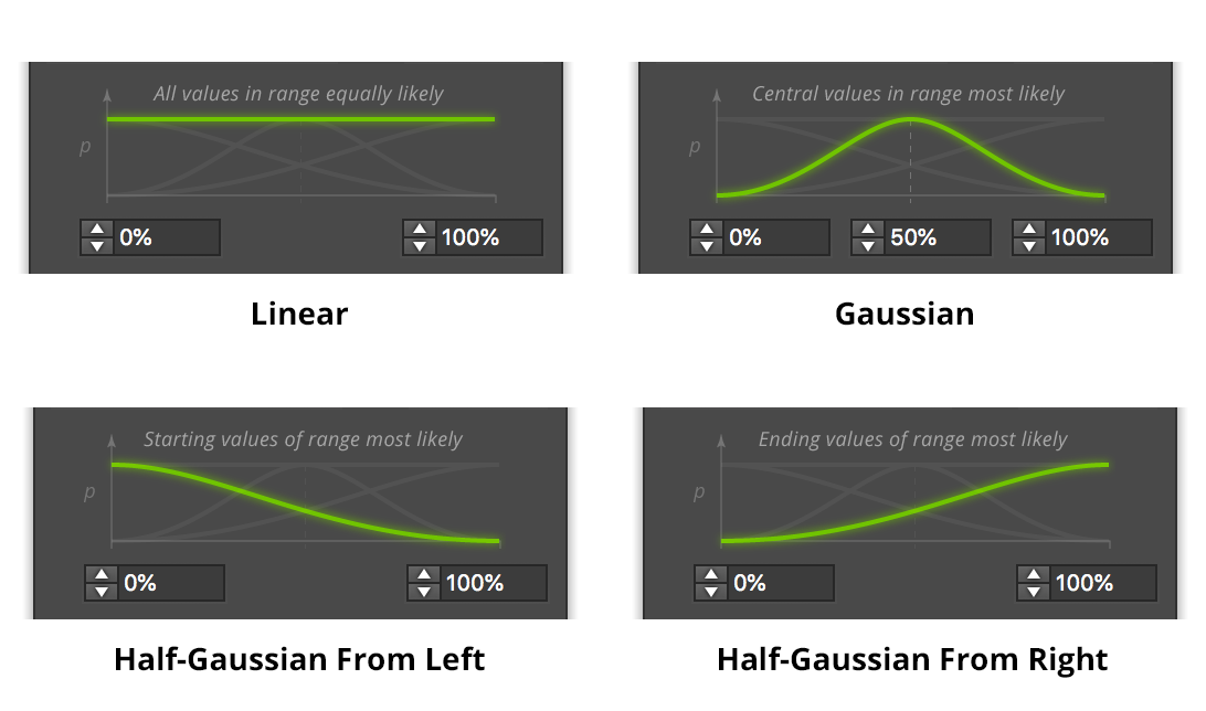
Randomino Distribution Curves
a) Linear distribution: all values within the range are equally likely to be chosen.
b) Bell curve (Gaussian) distribution: values at the center of the range are most likely to be chosen, with values becoming less likely the further they are from the midpoint (“outliers”). This is also known as a “Normal” distribution, and is prevalent in the natural world.
c) Half-Bell curve (Half-Gaussian) From Left distribution: values at the start of the range are most likely to be chosen, with values becoming less likely moving towards the end of the range.
d) Half-Bell curve (Half-Gaussian) From Right distribution: values at the end of the range are most likely to be chosen, with values becoming less likely moving towards the start of the range.
4. Value input boxes (range mode only)
The values between which the random value will be chosen according to the specified distribution. The mid-value is only displayed when the Bell curve (Gaussian) distribution is active.
5. Step checkbox and value (range mode only)
When enabled, whatever random values are chosen will be rounded to be multiples of the specified step. Note that this may cause the final value to lie outside the specified range. For example, if the range is 0 to 14, and the step is 5, the only values that will be chosen are 0, 5, 10, and 15.
6. Randomize button
Clicking the button randomizes the art using the parameters currently displayed on the panel.
7. Ignore Grouping checkbox
Acts the same as in the Randomini tool; when enabled, grouped items will be treated as if they were ungrouped. For example, consider a group of 10 squares. Applying a random rotation to the group would normally rotate the ten squares together, as a group. But when the preference is enabled, each square is independently rotated by a different amount, as if the squares were not grouped.
8. Value list (list mode only)
The values from which one will be randomly chosen. Duplicates are allowed if the Allow Duplicates checkbox is enabled (see below).
9. Add button and input (list mode only)
Adds the specified value to the list.
10. Delete button (list mode only)
Deletes one or more selected values from the list.
11. Allow Duplicates checkbox (list mode only)
When enabled, allows the same value to be added to the list more than once. This can be useful for modifying the frequency of each item. For example, if the list were to contain 0, 0, 0, and 90, then roughly three-quarters of the returned values would be zero and one-quarter would be 90. If duplicates exist in the list and the checkbox is changed from ticked to unticked, those duplicates are immediately removed.
12. Flyout menu
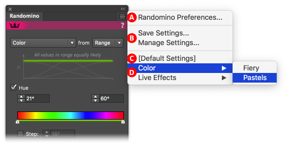
Randomino Panel Flyout Menu Callouts
A. Access to preferences dialog
B. Saving and managing settings: Saving a setting lets you store the set of panel options and settings that are currently being displayed in the panel, which can then be instantly recalled later. Saved settings can also be applied through an action.
C. Default settings: Restores the panel to its default values, retaining the randomization kind that is currently active.
D. Settings access: For organization and ease of access, each saved setting is found under a submenu according to kind. Picking the menu item loads that setting into the Randomino panel. If the preference “Apply Loaded Settings Immediately” is enabled, the setting is then applied to any selected art.
13. Panel banner
The help button on the right opens the help documentation in the Astute Manager. If this does not automatically appear, please ensure your Astute Manager is running first.
Illustrator Location:
Illustrator Main Menu > Window > Astute Graphics > Width Selector
Width Selector is an Astute Graphics tool and panel for Adobe Illustrator for visualizing and adjusting the width markers on paths with variable width strokes. It is an alternative to the native Width tool, and allows you move markers proportionally along a path; evenly distribute markers along a path; change the width of, average, or smooth multiple markers; duplicate one or more markers; quickly create tapered width profiles, easily convert uniform width strokes to variable width, and more. Width Selector is part of the WidthScribe plugin.
Illustrator Location:
Advanced Toolbar > Eraser Stack > AG Trim and Join Tool
AG Trim and Join is an Astute Graphics tool for Adobe Illustrator that allows parts of paths to be trimmed simply by dragging over them. Optionally, it can automatically join together the resulting pieces to form new paths. AG Trim and Join is part of the DynamicSketch plugin.
Tool Location and Cursor Appearance
The AG Trim and Join tool appears in Illustrator’s main toolbar (which must be in Advanced mode: View > Toolbars > Advanced), stacked under the native Eraser and Scissors tools. As with other stacked tools, click and hold on the top tool icon to display the tools stacked under it.
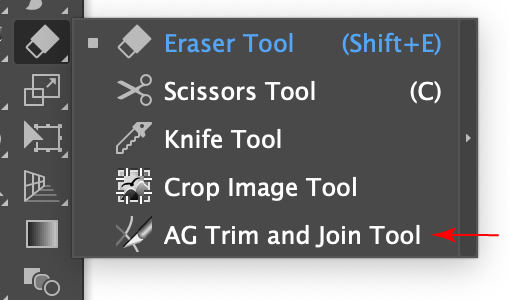
AG Trim and Join Tool Location
The AG Trim and Join tool’s cursor looks like the tip of a precision utility knife:
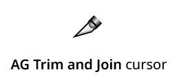
AG Trim and Join Tool Cursor
Illustrator Location:
Advanced Toolbar > Width Gradient Stack > Width Selector Tool
The Width Selector tool appears in Illustrator’s main toolbar (which must be in Advanced mode: View > Toolbars > Advanced), stacked under the Width Gradient tool. As with other stacked tools, click and hold on the top tool icon to display the tools stacked under it.

Width Selector Tool Location
The Width Selector tool’s cursor looks like an inverted “V,” similar to the Astute Graphics PathScribe tool, but with its opposite leg thicker, so as to distinguish it. Badges may be added when marquee selecting:
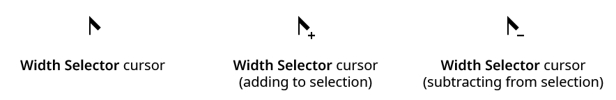
Width Selector Cursors
Illustrator Location:
Illustrator Main Menu > Window > Astute Graphics > Space Fill
Space Fill is an Astute Graphics panel for Adobe Illustrator for randomly filling the bounds of a path with one or more art objects. The uniformity of the fill can be specified, as can the number of copies, scaling, rotation, and opacity of the filling objects. Space Fill is part of the ColliderScribe plugin.
Illustrator Location:
Illustrator Main Menu > Window > Astute Graphics > Phantasm > Curves
Phantasm Curves is a live effect/filter that allows color correction of artwork using a curve, similar to Photoshop. As a live effect, it is accessible through the main menu, under Effect > Phantasm > Curves. It can also be applied directly from the Appearance panel using the “Add New Effect” button at the bottom of the panel, or through the Phantasm panel (see Phantasm: Panel).
After applying the live effect using the menu item (or when clicking on the existing effect in the Appearance panel to edit it), the parameters dialog will appear:
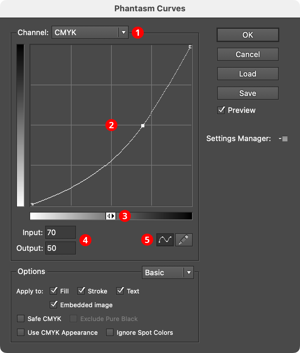
Phantasm Curves Dialog
1. Channel Menu
Specifies which channel or channels the current curve applies to. For CMYK documents, this includes the composite four process colors (CMYK) as well as each individual color. For RGB documents, this includes the composite three primary colors (RGB) as well as each individual color. In both cases, individual spot colors will also appear in the list, as well as Image Alpha, which affects the alpha channel in images with transparency.
Modifying the curve of Image Alpha can be useful for adjusting the output of native live effects which produce an embedded image with transparency, such as Drop Shadow, Outer Glow, and Gaussian Blur:
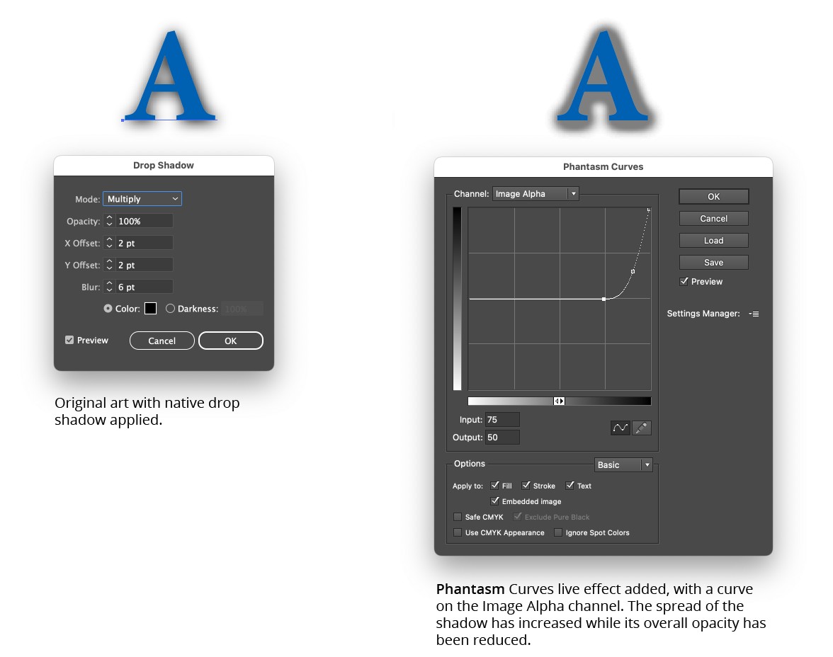
Phantasm Curves Example
2. Curve Graph
The horizontal axis of the graph represents the original brightness values (input levels). The vertical axis represents the new brightness levels (output levels). With the default diagonal line, no colors have been mapped to new values, so all colors have the same input and output values. Nodes on the curve may be moved simply by clicking and dragging them (or their input and/or output values may be modified, see below). A new node may be added by clicking at a spot along the curve which does not already have a node. A node (except the one at the beginning and the one end of the curve) may be deleted by dragging it off the graph area.
By default, the graph has a 4×4 grid, but Option/Alt-clicking on the graph will change the grid to 10×10.
3. Tonal Bar
By default, the graph goes from 0% (white) at lower-left to 100% (black) at upper right, but clicking on the tonal bar icon or the tonal bar itself will switch the graph to go from 0 (black) at lower-left to 255 (white) at upper right.
4. Input/Output levels
These values reflect the selected node, and may be edited to re-position the node.
5. Curve/Map Mode Buttons
By default, the graph is shown as a curve running through individual nodes, but by clicking on the Map button (pencil icon), each point along the axis may be freely drawn on the graph, and may contain discontinuities. Drawing across an existing graph will overwrite the previous lines. If a graph has been drawn in Map mode and the Curve mode button is pressed, Phantasm will approximate the lines as best as it can using a continuous curve. If no nodes are edited and the mode is switched back to Map, the original lines will be restored.
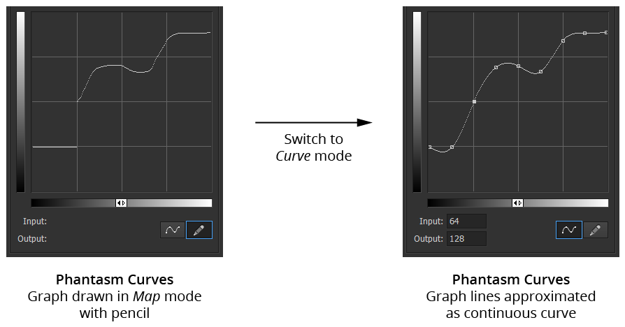
Phantasm Map Mode to Curve Mode
Illustrator Location:
Illustrator Main Menu > Window > Astute Graphics > PathScribe
The PathScribe panel allows you to numerically edit anchor points and their handles, as well as perform certain operations on one or more points or paths. Its flyout menu also allows you to select handles and points, perform certain path operations, change the layout of the panel, and bring up the Preferences dialog. The panel has two different appearances depending on whether multiple handles are selected. You can show or hide the PathScribe panel using the menu command Window > Astute Graphics > PathScribe.
Illustrator Location:
Illustrator Main Menu > Window > Astute Graphics > Opacity Brush
Opacity Brush is an Astute Graphics tool for Adobe Illustrator that allows art objects to be partially erased simply by brushing over them. The brush has variable size, opacity, hardness, roundness, noise, and angle, and has pressure support for an input device like a Wacom stylus. Brush parameters and other operations such as inverting or resetting the opacity mask that is created by the brush are controlled through an associated panel. Opacity Brush is part of the Texturino plugin.
Illustrator Location:
Illustrator Main Menu > Window > Space Fill > Panel Flyout Menu
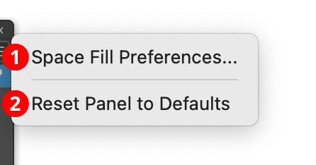
Space Fill Flyout Menu
1. Space Fill Preferences...
Brings up the Preferences dialog.
2. Reset Panel to Defaults
Resets all panel settings to their default values (Random Seed: 0; Method: Centers; Uniformity: 7; Resize All Filling Art: Off; Vary Size: Off; Vary Rotation: On, 360°; Step: Off; Rotate Gradients: On; Vary Opacity: Off; Multiply Filling Art: Off; Clip Contents: Off).
If one or more Space Fill objects are selected when the menu item is chosen, their settings will also be changed.
Illustrator Location:
Illustrator Main Menu > Window > Astute Graphics > Reprofile
Reprofile is a plugin tool for Adobe Illustrator which lets you add a "profile", or extra geometry, to an entire path or portion of a path. It is designed to add complexity to basic paths, whilst keeping the broad path shape the same. It consists of a tool and an associated panel, together with dialogs for managing the library of supplied and user-defined profiles.
After installing the plugin, the Reprofile tool will show up in Illustrator's main toolbar (which must be in advanced mode: Windows > Toolbars > Advanced)
Reprofile Toolbox Icon
Click on the Reprofile tool in the toolbar to select it. If you use the tool frequently, you may wish to assign it a keyboard shortcut key through Illustrator's Keyboard Shortcuts dialog (Edit > Keyboard Shortcuts...). You can also click on the Reprofile panel to activate the Reprofile tool.
If you have Astute Graphics' DirectPrefs plugin installed, and its Auto Open Astute Graphics Panels preference enabled (enabled by default), then selecting the Reprofile tool will automatically show the Reprofile panel. Otherwise, if the panel is not visible, choose Window > Astute Graphics > Reprofile.
While the Reprofile panel is not required in order to use the tool and reshape paths, it does contain various settings, options and commands that can only be accessed there, in particular, you will need the panel to select the Profile to apply.
For now, with a document open, simply hover the Reprofile tool's cursor over a basic path. The path (or a section of it) will highlight (the default color is blue). Press the mouse button down and drag out with the tool. You will see a new, red line appear, which is a preview of the reprofiled path. How far you drag determines the height of the profile applied to the path at that point. The blue outlines are for visual guidance only, they will not appear when the profile is applied.
To finalize the reprofile, press the Return or Enter key, or click the Apply button on the Reprofile panel. The newly-reprofiled path remains selected. If the profile contains more than one path, the target path will be turned into a compound path. If the key path of the profile is suppressed, a closed target path will become an open target path.
To add the reprofiled path, whilst still keeping the original, Option/Alt + Return or Enter, or holding down Option/Alt when clicking the Apply button, will retain the original artwork, creating the reprofiled section above it.
Illustrator Location:
Illustrator Main Menu > Window > Astute Graphics > PathScribe > Panel Flyout Menu
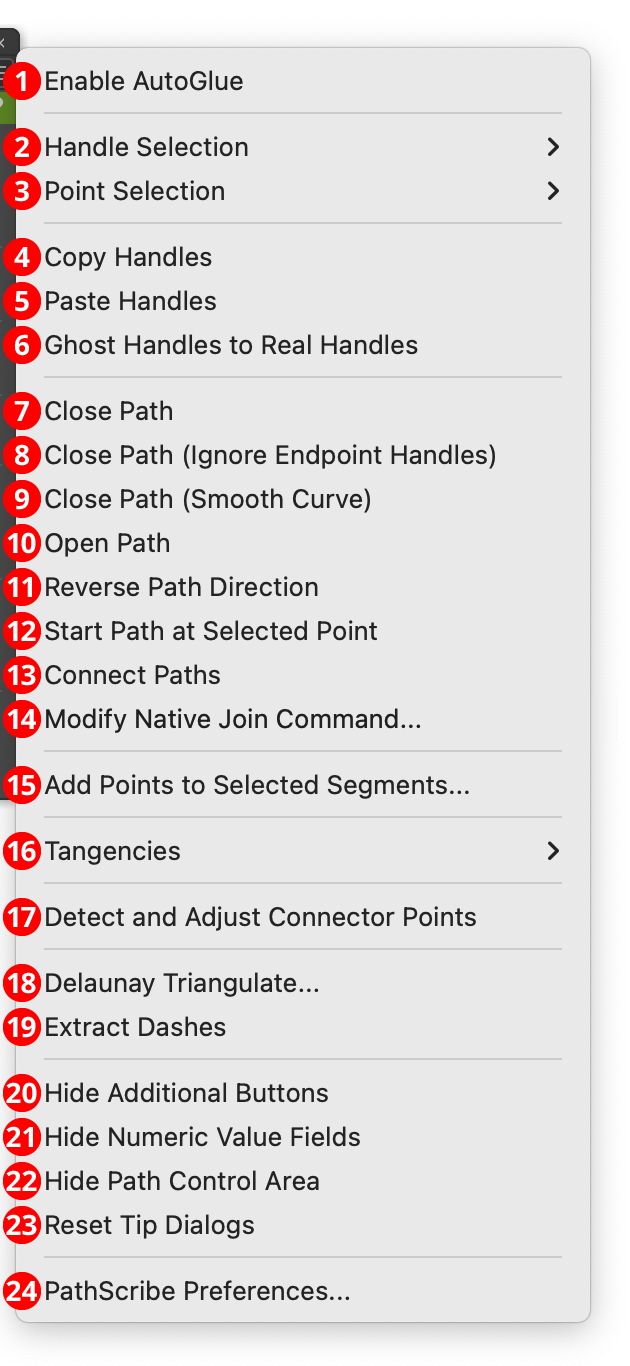
PathScribe Panel Flyout Menu
The PathScribe panel flyout menu and related submenus are shown here with all items enabled; in actual use, items which are not applicable in the current context would be disabled. Additionally, some of the menu items may change their wording slightly depending on context. For example, the Hide Additional Buttons menu item will say Show Additional Buttons if the buttons are already hidden.
1. Enable/Disable AutoGlue
AutoGlue is a feature of the PathScribe tool that enables anchor points (and/or handles) that lie directly on top of each other to be treated as if they were temporarily “glued” together, thereby allowing them to be moved together even if they aren’t all selected. The feature is disabled by default. When first enabled, a tip dialog with a short summary will be displayed.
Normally, dragging an anchor point without marquee-selecting multiple points will only affect the topmost path, even if other anchor points sit at the same position:
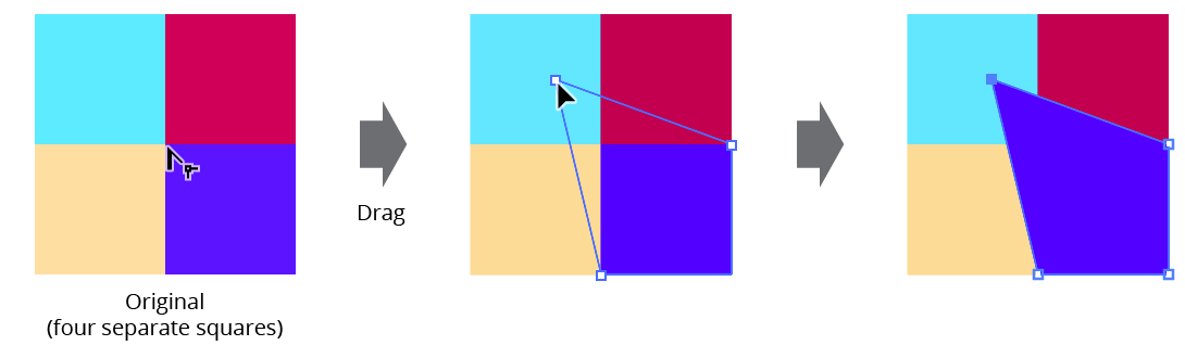
PathScribe Example Without AutoGlue Enabled
But when AutoGlue is enabled, all anchor points with the same coordinates will act as though they were “glued” together, and will move as one:
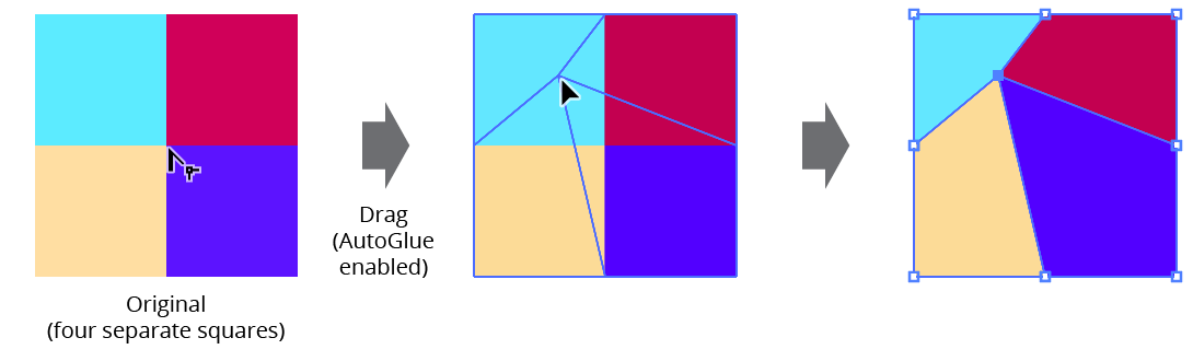
PathScribe Example With AutoGlue Enabled
AutoGlue also works on entire path segments: if two paths share a segment (both the anchor points at each end and their inward-facing handles, if any, all lie on top of each other), then editing the path segment (reshaping, dragging out or converting ghost handles, and adding or deleting points) with AutoGlue enabled will simultaneously edit the “glued” segments:
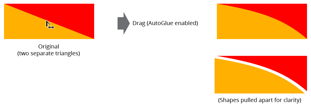
PathScribe AutoGlue Example Reshaping Segments
AutoGlue is especially useful when working with artwork created with generative AI, since this type of art is often composed of non-overlapping paths with common edges. A tolerance value, used to determine whether coordinates are considered identical, is specifiable in the PathScribe preferences.
2. Handle Selection submenu
PathScribe Panel Flyout submenu
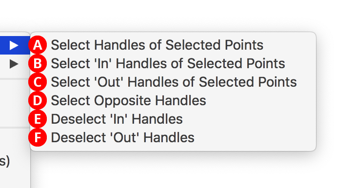
A. Select Handles of Selected Points
When there are one or more points selected, selects all of the handles on all of the selected points and enters Multi-Handle mode. The PathScribe tool will automatically be selected afterwards if it is not already so you can work with the selected handles.
Shift+Option/Alt-clicking on an empty area of the canvas with the PathScribe tool does the same thing as choosing Select Handles of Selected Points but is much easier.
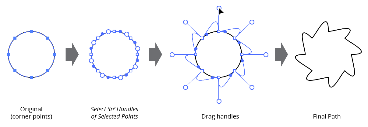
B. Select ‘In’ Handles of Selected Points
C. Select ‘Out’ Handles of Selected Points
Same as A., but only selects handles of the specified type.
Select in and out handles PathScribe
D. Select Opposite Handles
[Enabled only in Multi-Handle mode] Selects an anchor point’s in handle if only the out handle is selected, and its out handles if only the in handle is selected. If both handles were originally selected, they both remain selected.
E. Deselect ‘In’ Handles
F. Deselect ‘Out’ Handles
[Enabled only in Multi-Handle mode] Removes all handles of the specified type from the handle selection.
3. Point Selection submenu
PathScribe point selection submenu
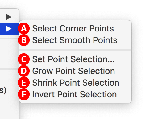
A. Select Corner Points
B. Select Smooth Points
Selects all anchor points of the specified type on all selected paths.
C. Set Point Selection...
Allows you to select points on selected paths by position, using the dialog that comes up:
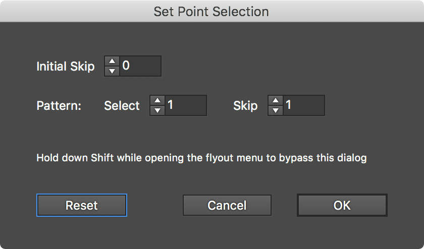
Point Selection PathScribe Skip Steps
The “Initial Skip” value specifies the number of anchor points to leave unselected, starting at point 0 of the path. Thereafter, the selection pattern is specified by the “Select” and “Skip” values, which specify the number of points in a row to select followed by the number to leave unselected. As the values are changed, the points which will be selected are dynamically highlighted on the artboard using magenta dots:
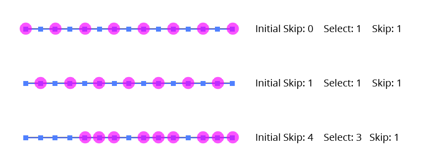
Point Selection PathScribe Skip Steps
You can bypass the dialog and use the values from the previous application of Set Point Selection by holding down Shift while choosing the menu item. The Reset button changes Initial Skip to 0, Select to 1, and Skip to 1 (i.e., every other point starting with the first). Holding down Shift while clicking the Reset button does the same except the Initial Skip is set to 1.
D. Grow Point Selection
Grows the current point selection by selecting one additional anchor point on either side of all points which are already selected.
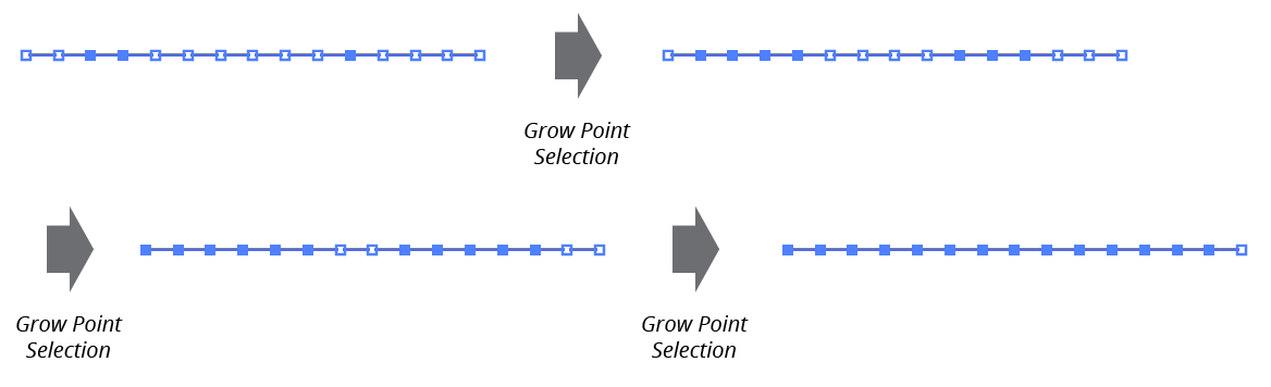
PathScribe Grow Point Selection
You can use the keypress assigned in the Keyboard Shortcuts dialog for “Decrease Diameter” (by default, the left bracket key – [) as a shortcut for growing the point selection.
E. Shrink Point Selection
Shrinks the current point selection by deselecting all anchor points which already have an unselected point on either side of them, or are on the end of an open path.
F. Invert Point Selection
Inverts the current point selection by switching unselected anchor points for selected points. Paths which were completely unselected to start remain unselected.
4. Copy Handles
Lets you copy the direction and length of a single handle, or, as long as they are the in and out handles of a single point, two handles. When both handles of a point are copied, the point type (corner or smooth) is also retained. The menu item is available when a single point is selected, or in Multi-Handle mode when one handle or the in and out handles of a single point are selected. The PathScribe tool does not need to be active when copying both handles from a single point. Copied handle and point type data is stored in an internal clipboard which is cleared only when Illustrator is quit.
5. Paste Handles
Lets you change both handles on any selected points (or specific, selected handles when in Multi-Handle mode) to match the handle(s) that were previously copied with Copy Handles. You can paste to multiple points on multiple paths, and the PathScribe tool does not need to be active. If a single handle was copied, then its data will be pasted to any selected handles, regardless of type (in or out), and any affected points will become corner points. If both handles of a single point were previously copied, then selected in handles will receive the copied in handle’s data, and selected out handles will receive the copied out handle’s data. If a point gets two new handles from two handles that were previously copied, then the previously-copied point type (smooth or corner) is also applied to it.
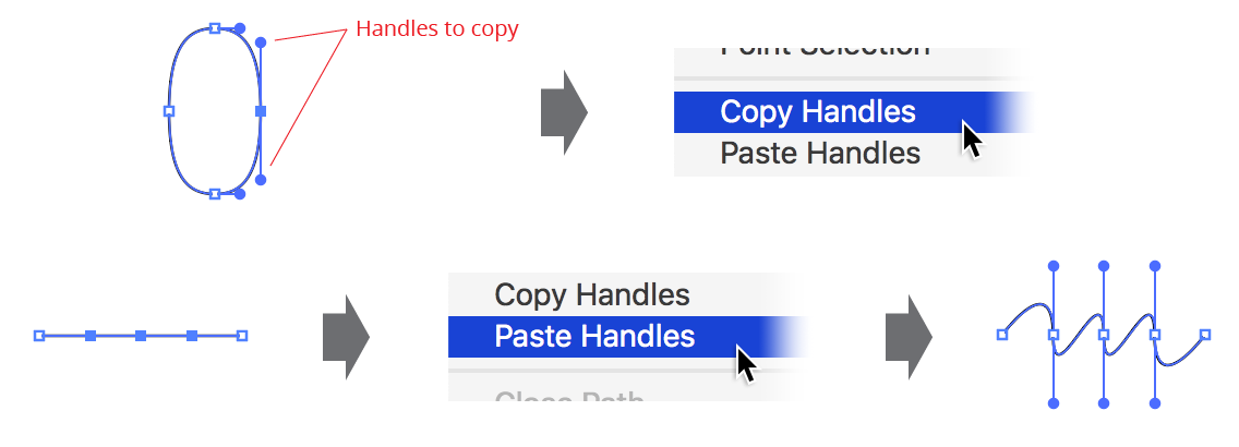
PathScribe copy paste handles
6. Ghost Handles to Real Handles
When one or more ghost handles are visible, converts them to real handles.
7. Close Path
8. Close Path (Ignore Endpoint Handles)
9. Close Path (Smooth Curve)
All these menu items close selected open paths; they differ in how handles for the new segment are created. Close Path honors existing handles; Close Path (Ignore Endpoint Handles) always results in a straight new segment without handles; Close Path (Smooth Curve) creates new handles for the segment such that it blends smoothly with the existing path segments:
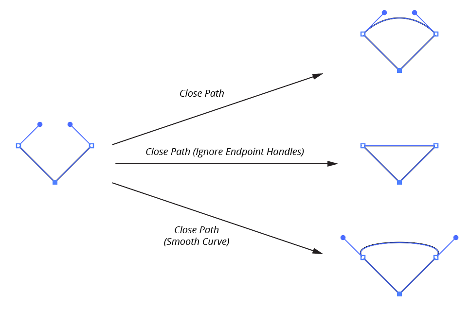
PathScribe Panel Flyout close path
10. Open Path
Converts all selected closed paths into open paths by removing the last segment (point count does not change). This can be useful for fixing paths that are simple two-point lines which have been inadvertently created or imported as closed paths.
11. Reverse Path Direction
Performs the identical function as the Reverse Path Button on the PathScribe panel, but is accessible even when the third row of panel buttons is hidden.
12. Start Path at Selected Point
Available when the selection consists of at least one closed path with exactly one selected point. Forces the closed path to begin at the selected point (it becomes “Point 0”). The change to the path is generally only visible when the path is stroked by a non-uniform brush, or has an arrowhead:
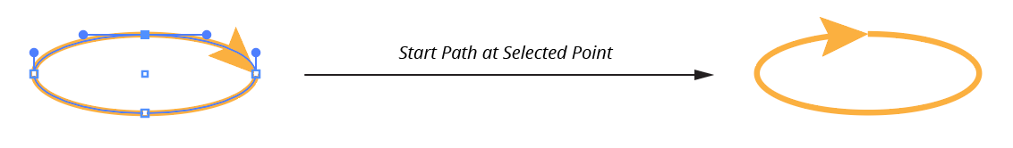
PathScribe Start Path at Selected Point
13. Connect Paths
Available when the selection consists of exactly two open paths, each with a single endpoint selected. Acts similarly to the native Join command, but instead of a straight joining segment, the joining segment will blend smoothly with the existing path segments:
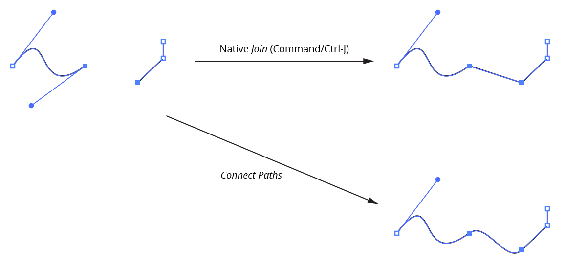
PathScribe Panels Connect Paths
14. Modify Native Join Command…
Allows the native Object > Path > Join menu command (typically called using the shortcut key Command/Ctrl-J) to join the selected paths with smoothly curved segments instead of the default straight segments. Choosing the PathScribe menu item will bring up a small dialog:
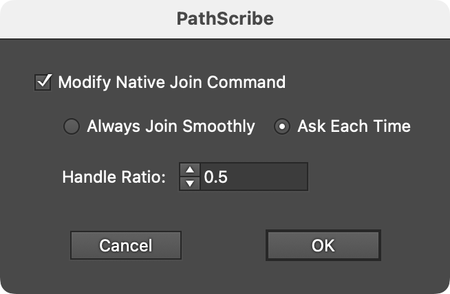
PathScribe Modify Native Join Dialog
Turning on the Modify Native Join Command setting will allow one of two methods to be used:
Always Join Smoothly: Whenever the Join command is used, the paths will automatically be joined smoothly with the originally-specified handle ratio. To join using straight segments, the PathScribe flyout menu item would have to be selected again to turn off or change the setting. Therefore, this setting is best used when you rarely want to join with straight segments, or need to adjust the handle ratio.
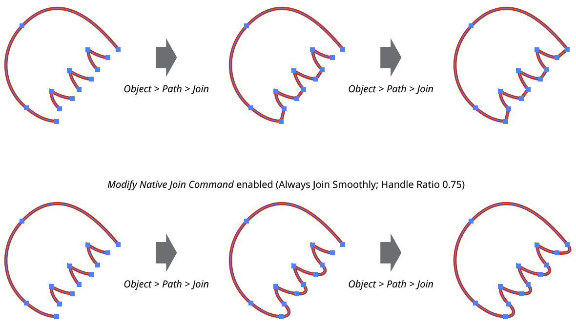
PathScribe Modify Native Join Command Example
Ask Each Time: Whenever the Join command is used, an additional dialog will come up immediately prior to its execution, allowing you to either join in the native way (straight segments), or with smooth curves. If the latter, the Handle Ratio can be changed as well (see below). The Join Type choice affects only that specific instance of the Join command, unless Always Use This Choice is enabled before the dialog is OK’d. In that case, the choice will be remembered and the dialog will not come up again unless the PathScribe flyout menu item is selected once again.
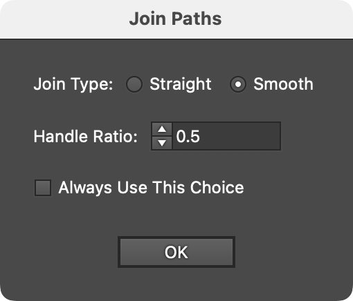
PathScribe Modify Native Join Ask Dialog
The Handle Ratio specifies the length of the automatically-generated handles, in relation to a default value. Higher ratio values will create longer handles, which make the joining curves “protrude” more. The ratio can be specified from 0.1 to 25.
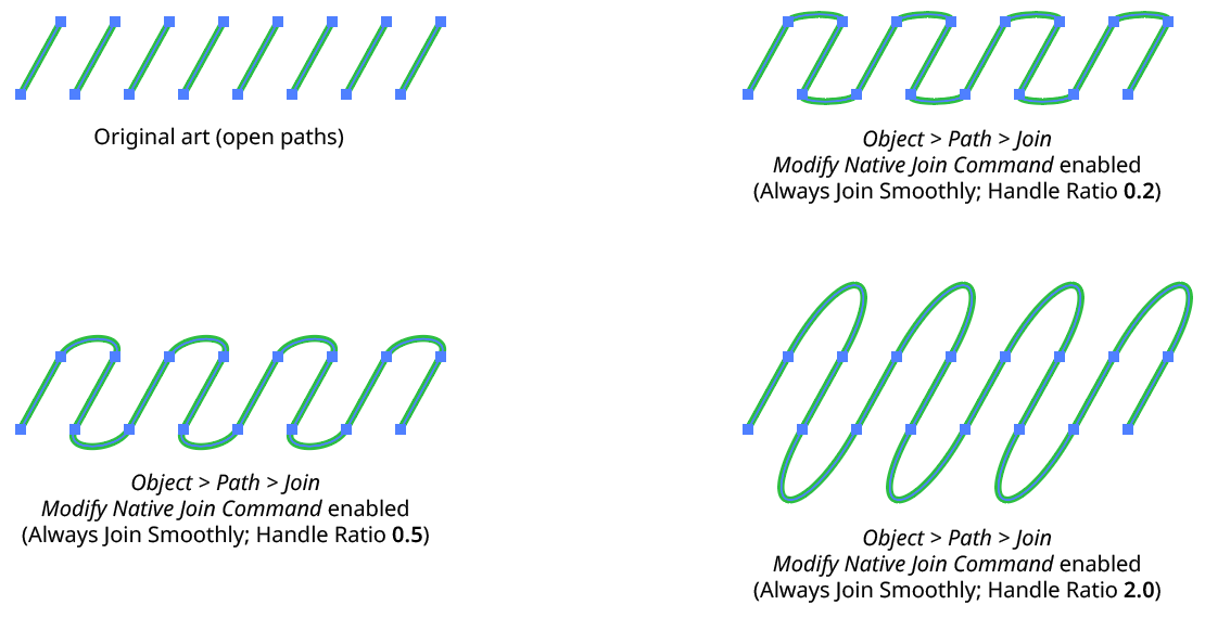
PathScribe Modify Native Join Command Handle Ratio
Note that the native Join command will not convert multiple open paths into a single closed path with a single use; it must be called twice to do this.
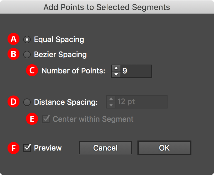
15. Add Points to Selected Segments...
Performs the identical function as the Add Points to Selected Segments Button on the PathScribe panel, but is accessible even when the third row of panel buttons is hidden.
PathScribe Add points to selected segments
There are three different spacing methods you can use to add points. For the first two, Equal Spacing and Bezier Spacing, you specify the number of points to add to each selected segment. Equal Spacing creates equal distances between points, as measured along the path. Bezier Spacing places the points such that there are equal distances between t-values, which are a mathematical property of the cubic bezier curves with which Illustrator’s paths are constructed:
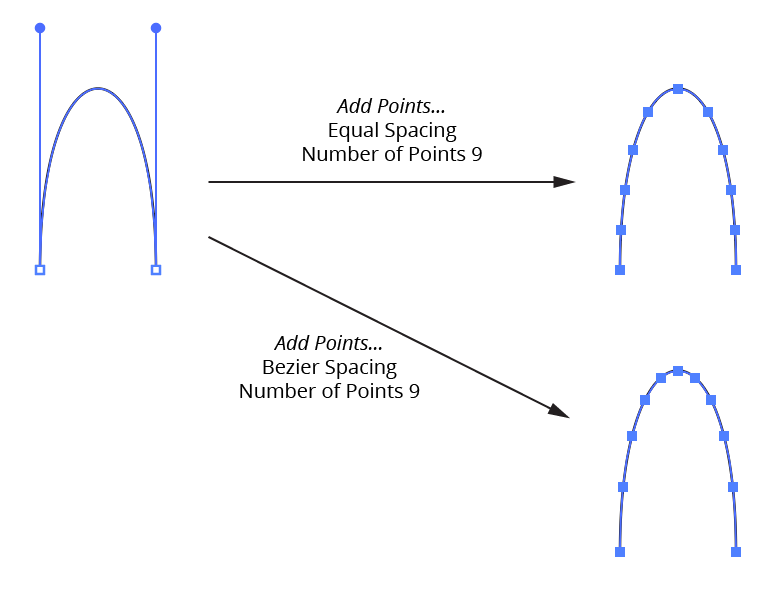
PathScribe Panel Add Point Equal Spacing
For Distance Spacing, you specify the distance between anchor points, as measured along the path. Since this distance will usually not exactly divide the total length of the segment, the “Center within Segment” option allows you to center the new points within each segment:
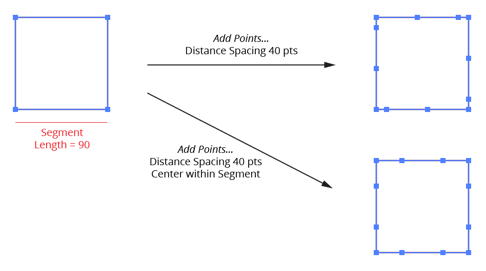
PathScribe Panel Add Points Distance Spacing
You can bypass the dialog and use the values from the previous application of Set Point Selection by holding down Shift while choosing the menu item.
16. Tangencies submenu
Tangencies are places along a path where the path’s direction (and therefore the direction of a line that is tangent to the path at that spot) is either vertical or horizontal (taking into account the general constrain angle). Certain drawing methods include the principle that anchor points along a curved path should be, whenever possible, located at these places of tangency.
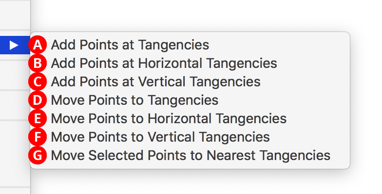
PathScribe Tangencies Flyout Submenu
A. Add Points at Tangencies
B. Add Points at Horizontal Tangencies
C. Add Points at Vertical Tangencies
These menu items add new anchor points, if needed, at places of tangency along all selected paths. Existing anchor points are not changed.
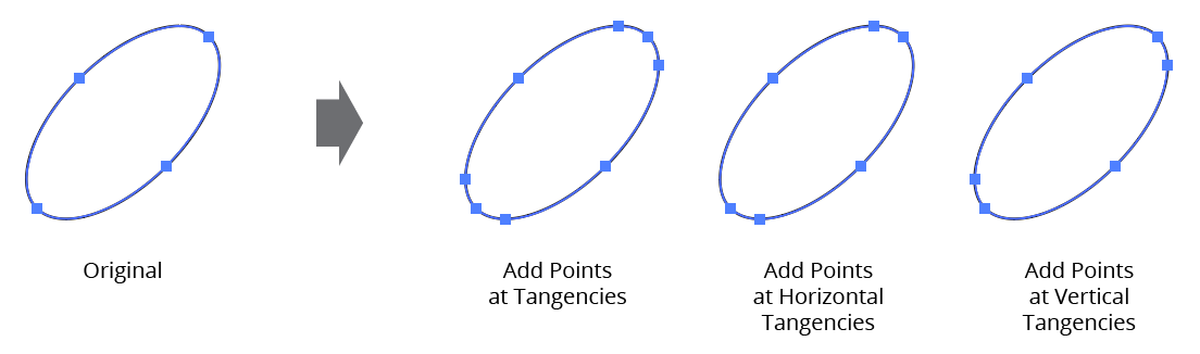
PathScribe Add points at tangencies flyout option
D. Move Points to Tangencies
E. Move Points to Horizontal Tangencies
F. Move Points to Vertical Tangencies
These menu items act similarly to their “Add Points...” counterparts, except that existing anchor points are removed after the tangent points are added if their removal does not alter the path shape appreciably.
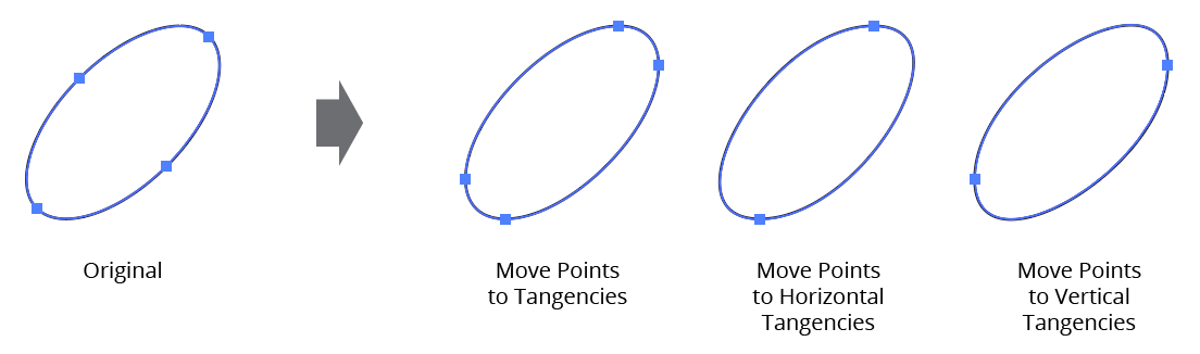
Move points to tangencies PathScribe flyout option
G. Move Selected Points to Nearest Tangencies
While the previous items affect every anchor point on a path, this item only moves points which are selected to the nearest horizontal or vertical tangency (if possible).
17. Detect and Adjust Connector Points
Enabled when the Recognize Connector Points preference is enabled, this menu item scans any selected paths for potential connector points and, if found, adjusts their handles.
18. Delaunay Triangulate...
Brings up a dialog which lets you set parameters for creating a “Delaunay triangulation” (a network of triangles) from the selected artwork.
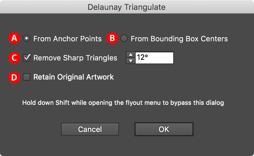
Delaunay Triangulate PathScribe
A. From Anchor Points
Triangles are created using anchor points on all selected paths.
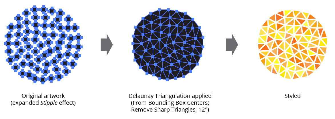
B. From Bounding Box Centers
Triangles are created using the centers of the bounding boxes of all selected art (groups are ignored).
This is useful when creating a triangulation from, say, an expanded Stipple live effect.
C. Remove Sharp Triangles
Delaunay triangulation can create sliver-like triangles that are often undesirable, so this setting lets you eliminate any triangles that have an angle smaller than the threshold value.
D. Retain Original Artwork
When enabled, the artwork used to create the triangles is left in place and the triangles (grouped) are placed above it.
When the Shift key is held down while choosing the menu item, the dialog will not be shown and parameter values that were previously in effect will be used.
Delaunay Triangulate Points PathScribe
19. Extract Dashes
Converts a path with a dashed stroke into a compound path made up of separate, non-dashed subpaths.
This can be useful for giving the dashes different styles, for example:
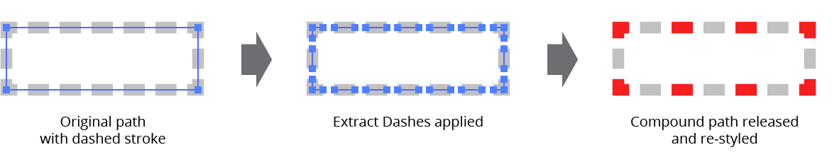
PathScribe flyout menu extract dashes
20. Show/Hide Additional Buttons
Shows or hides the third row of buttons on the PathScribe panel. When hidden, most of the buttons’ functionality can still be accessed through the flyout menu commands.
21. Show/Hide Numeric Value Fields
Shows or hides the center section of the PathScribe panel which shows anchor point and handle coordinates.
22. Show/Hide Path Control Area
Shows or hides the bottom Path Control area of the PathScribe panel.
23. Reset Tip Dialogs
If the “Don’t show again” checkbox was used on any tip dialogs (such as the AutoGlue dialog that appears when the feature is enabled), this resets the dialogs so they are shown again.
24. PathScribe Preferences...
Brings up the Preferences dialog.
Illustrator Location:
Advanced Toolbar > Selection Stack > Rotate at Collisions Tool
Rotate At Collision is an Astute Graphics tool for Adobe Illustrator. By dragging a path with the Rotate At Collision tool to another path, the dragged path is rotated to position it against the stationary path, either tangently or perpendicularly, depending on the path geometries. The tool also allows the positioning of point text objects. An option to automatically add anchor points to the paths at their touching spots is provided. Rotate At Collision is part of the ColliderScribe plugin.
Tool Location and Cursor Appearance
The Rotate At Collision tool appears in Illustrator’s main toolbar (which must be in Advanced mode: View > Toolbars > Advanced) stacked under the native Selection tool along with ColliderScribe’s other tools. As with other stacked tools, click and hold on the top tool icon to display the tools stacked under it.
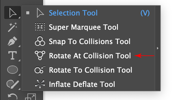
Rotate at Collision Tool Location
The Rotate At Collision tool’s cursor changes depending on what the tool is currently doing:
Rotate at Collisions Tool Cursors
Additionally, a small dot will appear next to the last two cursors when the Add Points to Paths at Collisions preference is enabled.
When hovering the Rotate At Collision cursor over artwork, it snaps (even without Smart Guides) to paths and point text objects; in this case a red ring and explanatory text appears at the cursor location:
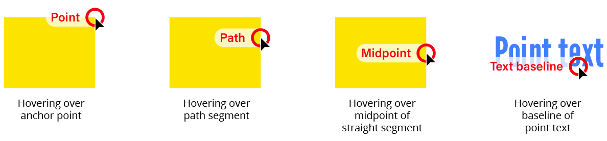
Rotate at Collisions Tool Snapping Rings
Illustrator Location:
Advanced Toolbar > Reprofile
The delimiters can be moved by dragging them. To disable snapping to anchor points, hold down Command/Ctrl while dragging. To quickly move the delimiters so that the entire path is affected by the Reprofile tool, doubleclick either one of them. For an open path, this will move them to the path's endpoints. For a closed path, this will enter “looped mode” (see below). If a delimiter is dragged such that a marker would fall outside of the newly-delimited portion of the path, the marker will be automatically deleted. If a marker is located exactly on a delimiter, then moving the delimiter will also move the marker.
Markers can be moved by dragging them within the delimited reshape extent. To disable snapping to the path's underlying anchor points, hold down Command/Ctrl while dragging. Dragging a marker by its circle annotation will allow you to freely change both its position along the path and its offset; to change only its offset, hold down Shift while dragging.
To change only its position, drag the marker's black line or black square annotation.
To select a single marker, click on its circle annotation.
Multiple markers may be selected by Shift + clicking them or by dragging a marquee over them in the normal manner. They can then be moved simultaneously.
To delete a marker, doubleclick its red square.
To create an additional marker, place the cursor over either the original or virtual reshaped path and click or click-and-drag.
To change a marker from smooth to sharp or vice versa while dragging it, press the X key.
When using the Reprofile tool, Astute Graphics’ AstuteBuddy panel should be kept open to show relevant keypresses.
Illustrator Location:
Illustrator Main Menu > Window > Astute Graphics > Reprofile
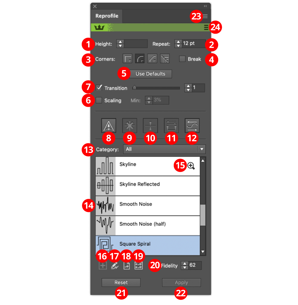
Reprofile Panel Expanded Overview
1. Height value
To numerically enter the height of the selected markers. Note that negative values are allowed and create a mirrored reprofile. It is possible to mix positive and negative markers.
2. Repeat value
Sets the width of the profile element, in document units. Note that this will be rounded to create a whole number of repeats. If scaling is enabled, the value is the average width of the scaled elements.
3. Corners buttons
When reprofiling a path with an abrupt change in path direction, the corner type specifies how the reprofiled path bends around the original corner.
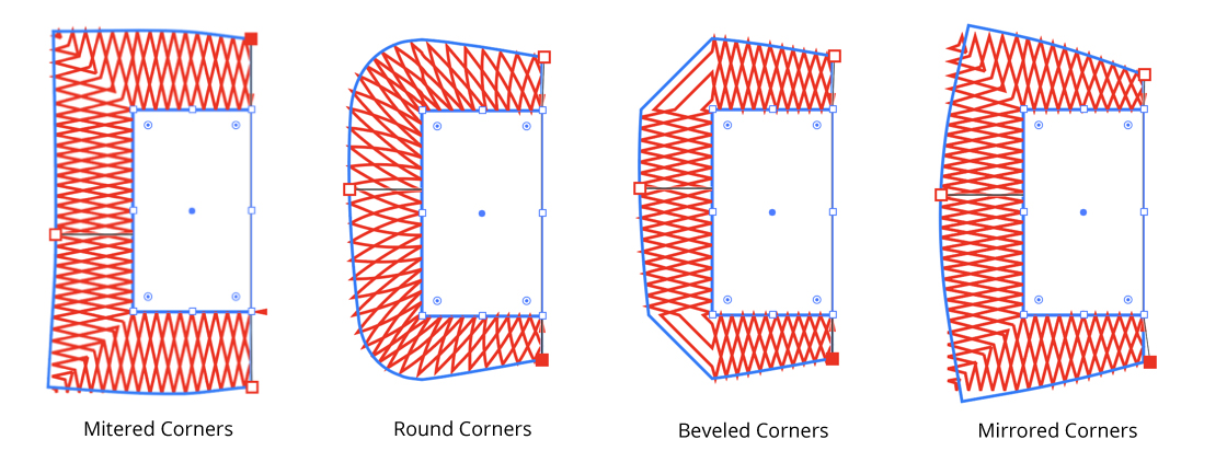
Reprofile Panel Corner Types
4. Break checkbox
Forces a whole number of repeats for each smooth section of the path without corners. This option is always enabled for mirrored corners.
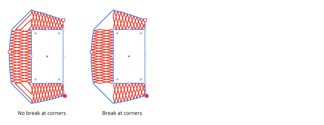
Reprofile Panel Corner Type Break
5. Use Defaults button
Sets the parameters to the values stored for the profile in the Profile Library. These can be edited in the Profile Attributes panel.
6. Scaling checkbox and value
When selected, profile width is varied by the height of the profile at that point. The minimum scaling value sets a minimum scaling to prevent profiles at very low points being scaled to tiny sizes.
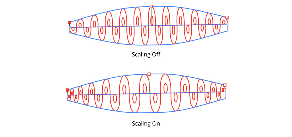
Reprofile Panel Scaling Option
7. Transition checkbox / value
Controls the smoothness of the transition between the original path and its reprofiled portion (off, or values of 1 - 10).
8. Sharp marker button
Toggles the selected markers between smooth and sharp (see above for explanation of different types). It also controls the type of any newly-created markers.
9. Delete marker button
Removes all selected markers.
10. Mirror offset button
Changes the direction of the height of all selected markers. This is the same as changing the sign of the height value.
11. Swap marker direction button
Changes the position of all markers (selected or not) along the reshape extent. If, for example, a marker is located 1/5 of the way from the start to the end delimiter, swapping the direction will change it to be 1/5 of the way from the end to the start delimiter. Offset values are not changed.
12. Flip profile direction button
Toggles the profile direction horizontally along the path.
13. Category dropdown
Sets the category of profile to display in the selection panel.
14. Profile selection panel
Selects the profile to use for reprofiling.
15. Profile zoom icon
Toggles the profile thumbnail displayed in the profile selection panel between small and expanded. Shift + clicking will toggle all the profiles. This is purely to aid in profile selection, it does not affect the behaviour of the tool.
16. Grab button
If artwork is selected, it will take the artwork and open the Profile Attributes Editor. If the profile is accepted, it will be added to the library. Option/Alt-click to overwrite the geometry of the currently selected profile (ie. edit the existing profile shape).
17. Profile edit button
Opens the Profile Attributes Editor to edit the attributes of the selected profile.
18. Profile dump button
Copies the selected profile to the artboard. Note that dumping and re-grabbing is the only way to edit the geometry of a profile.
19. Profile Manager button
Opens Profile Manager. Profile Manager allows you to import, export, and delete profiles.
20. Fidelity control
Controls the accuracy with which paths are reprofiled. A high value means greater accuracy, but longer processing time. For technical reasons, artifacts will also occasionally appear if fidelity is too high. A lower fidelity value also maintains more straight lines. You might consider editing with a lower fidelity to retain interactivity, then setting the value higher before applying.
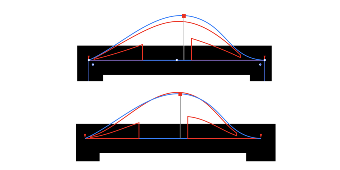
Reprofile Panel Fidelity Option
Scale: the thick black line is a path of one point width.
Low fidelity: the short lines are interpreted as straight lines.
High fidelity: the short lines are curved to follow the width profile.
21. Reset button
Cancels the Reprofile operation. The path remains unmodified. This can also be achieved by pressing the Esc key when the cursor is in motion.
22. Apply button
Finalizes the path reprofile. This can also be achieved by pressing Return or Enter. Holding down Alt/Option will cause the original artwork to be retained.
23. Flyout menu
Provides access to the preferences dialog, and allows saving and recalling of height marker settings.
24. Panel banner
The help button on the right opens the help documentation in the Astute Manager. If this does not automatically appear, please ensure your Astute Manager is running first.
Click on the other area of the color bar to activate the Reprofile tool. This is a quick method of locating the tool within the default Advanced toolbar or a custom toolbar.
Illustrator Location:
Illustrator Main Menu > Window > Astute Graphics > Dynamic Shapes
The Dynamic Shapes component of VectorScribe consists of the Dynamic Shapes tool and the Dynamic Shapes panel. While the tool can be used alone, much of Dynamic Shapes’ functionality is accessed through the panel. With Dynamic Shapes you can create and modify paths with fourteen different shape types:
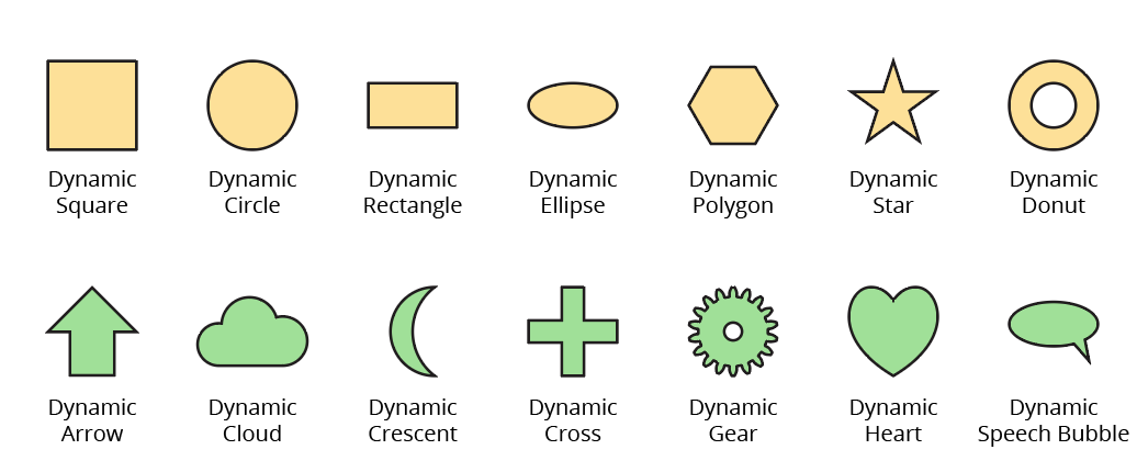
Dynamic Shapes Overview and Types
The seven shapes in the top row are “standard” and can include corners and slicing. All shapes types can have their rotation and size (and often other parameters) changed, and all remain “live,” meaning those parameters can be changed at any time, unless the path is externally edited in a way that destroys the integrity of the shape.
When the Dynamic Shapes tool is selected, a path which is a Dynamic Shape can be identified by a circular crosshair annotation (red, by default) that appears at the transformation point of the shape (at its center, by default). If the path is selected, additional annotated controls will also appear:
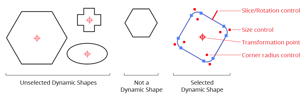
Dynamic Shapes Identifiers
Although they contain metadata, Dynamic Shapes are still normal paths. Files with Dynamic Shapes may be opened on a machine without VectorScribe installed without issues.
Illustrator Location:
Advanced Toolbar > Dynamic Shapes Tool
Dynamic Shapes Tool Location
The Dynamic Shapes tool is used to create new shapes, select existing shapes, edit existing shapes, or convert ordinary paths to Dynamic Shapes. Except when it is editing a Dynamic Shape through an annotated transformation point or control point, its cursor looks like a crosshair.
Illustrator Location:
Illustrator Main Menu > Window > Astute Graphics > Width Gradient
Width Gradient is an Astute Graphics tool and panel for Adobe Illustrator that allows you to change the stroke widths along one or more paths by simply dragging across them. Paths are changed to variable width if necessary, such that their widths at any spot are based on their positions along the drawn virtual linear or radial gradient. Width Gradient is part of the WidthScribe plugin.

Width Gradient in Action
Illustrator Location:
Illustrator Main Menu > Window > Astute Graphics > Texture Brush
Texture Brush is an Astute Graphics tool for Adobe Illustrator that allows local changes to the opacity of a Astute Texture live effect (using an opacity mask) through a brush interface. The brush has variable size, opacity, hardness, roundness, noise, and angle, and has pressure support for an input device like a Wacom stylus. Brush parameters and other operations such as inverting or resetting the texture’s opacity mask are controlled through an associated panel. Texture Brush is part of the Texturino plugin.
Illustrator Location:
Illustrator Main Menu > Window > Astute Graphics > Dynamic Shapes
The Dynamic Shapes panel is used in conjunction with the tool to change existing shape types; to set shape parameters numerically (including parameters which can’t be changed using the tool alone); and to access several utility functions. When the Dynamic Shapes tool is not in use, the panel displays only a “Click to select” message; clicking anywhere on the panel selects the tool and displays all the controls.
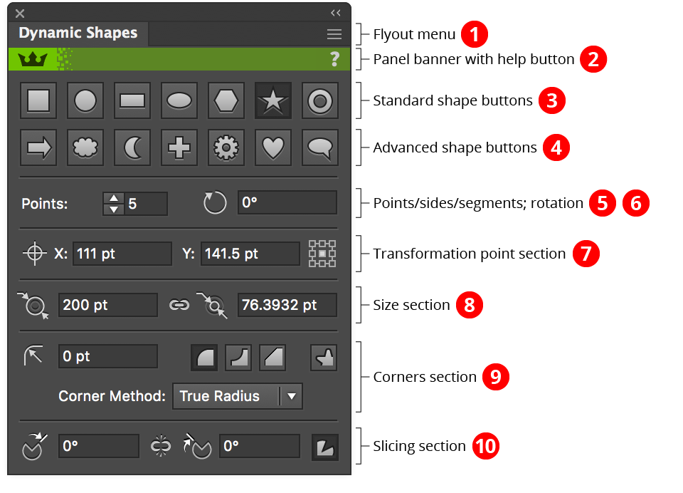
Dynamic Shapes Panel Overview
1. Flyout menu
See Dynamic Shapes Panel: Flyout Menu.
2. Panel banner
The help button on the right opens the help documentation in the Astute Manager. If this does not automatically appear, please ensure your Astute Manager is running first.
Click on the other area of the color bar to activate the Dynamic Shapes tool. This is a quick method of locating the tool within the default Advanced toolbar or a custom toolbar.
3. Standard Shape Buttons
4. Advanced Shape Buttons
By default, standard shapes are shown on a separate row from the advanced shapes. This can be changed in the preferences to make the panel shorter; when all the shape buttons are shown in a single row, arrow buttons can be used to switch to the beginning and end of the row:
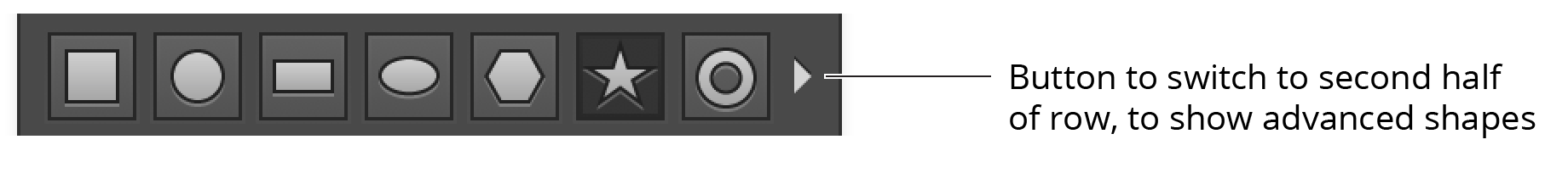
Dynamic Shapes Single panel shape row
Clicking on a shape button changes all selected Dynamic Shapes to the chosen type, altering any other parameters only when necessary (for example, a square being turned into a star may have corners larger than the star can support; in this case, the corner radii will be changed to the maximum value that the star can accommodate).
5. Points/Sides/Segments Value
When the shape supports a variable number of points, sides, etc., this control is enabled and allows you to change the value, between a minimum of 3 and a maximum of 1000.
6. Rotation value
Allows changing the rotation of all selected shapes. Dynamic Shapes measures rotation values with zero degrees pointing up, and positive values increasing a clockwise direction.
7. Transformation Point Section
A Dynamic Shape’s transformation point is the point relative to which rotation and scaling are done. The coordinates of the transformation point may be specified numerically, and the location of the point (relative to the shape’s bounding box) can be changed by picking of the nine standard positions using the control on the right. When multiple shapes with different transformation point locations are selected, or when the transformation point has been moved to a custom position using the tool, none of the locations on the control will be highlighted.
By holding down Option/Alt when clicking to change the transformation point location, the Dynamic Shape will be moved relative to the point, rather than the point moving.
8. Size Section
Some Dynamic Shapes have their size specified by only a single dimension (width/outer diameter). These include the square, circle, polygon, cloud, and crescent. All other shapes have a second, independent dimension: height or inner diameter. A standard “link” icon between the two input fields can be clicked to specify whether changing one dimension will also change the other (which is done proportionally). Polygons may have their outer diameter or side length specified, but these are not independent sizes. Sizes may range from 0 to 16384 pt.
Shift+Command/Ctrl-clicking on the link icon is a shortcut which can be useful after converting native art to rectangles and ellipses. It rotates the shape 90° counterclockwise (add Option/Alt for clockwise rotation) but simultaneously swaps the width and height parameters, so the rotated art looks the same.
9. Corners Section
This section controls the corners that may be added to the seven standard shapes. Corners may be one of three types: Regular (a curve facing outwards); Negative (a curve facing inward); or Chamfered (a straight line cutting across the corner).
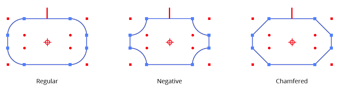
Dynamic Shape corner types
The corner type buttons on the Dynamic Shapes panel change the type of all of the shape’s corners. To change the type of only one corner, use the Dynamic Corners tool to select and edit it.
For corner types with curves (i.e., Regular and Negative), you may also specify the method used to create the curve by choosing it from the popup menu. A Dynamic Shape can only have one corner method, shared by all corners.
True Radius method corners are created with one or two circular segments and maintain a constant radius as closely as is possible using the cubic bezier curves with which all Illustrator paths are constructed.
Standard method corners are the type that the native “Round Corners” live effect creates. When placed on a right angle, they are identical to True Radius corners, but at other angles they are of non-constant radii, the values of which vary substantially from the nominal radius value.
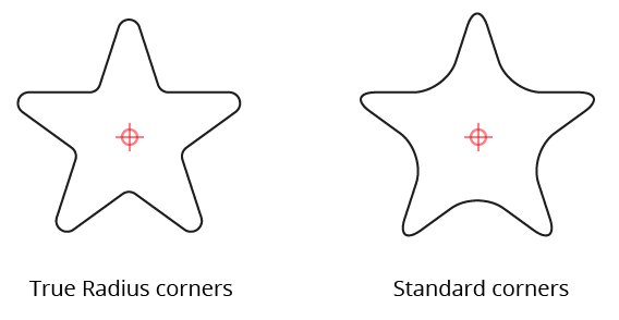
Dynamic Shapes Standard corner methods
Squircular method corners approximate the “Squircle” curve popularized by Apple. A squircle is a blend between a square and a circle. These non-constant-radius corners feature a smoother transition between the curved section and the straight section of path, and are most useful on the right angles of squares and rectangles.
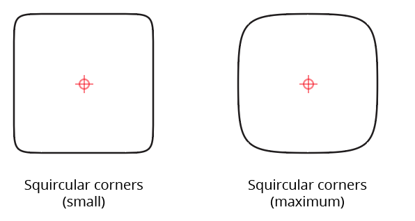
It may seem meaningless to to apply a “corner” to a circle or ellipse, and indeed, Regular corners have no effect on the appearance of these shapes (although they do add extra anchor points). However, using Negative or Chamfered corners allows the creation of some potentially useful geometry:
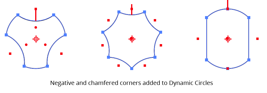
Dynamic Shapes Negative Chamfered Corners
The radii of corners on a Dynamic Shape cannot be increased beyond the point when one of their endpoints reaches the midpoint of one of the two adjacent segments, even if it might have space to go past this point. To enlarge a corner past this limit, you must remove the shape’s dynamic status (see Dynamic Shapes Panel: Flyout Menu) and use the Dynamic Corners tool to edit the corner.
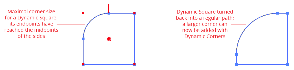
Dynamic Shape corner size limits
Dynamic Star shapes have one additional setting that is controlled by the button on the right side of the corners section of the panel. It determines whether or not a Dynamic Star’s corners appear on all of its points (both inner and outer), or only the outer points:
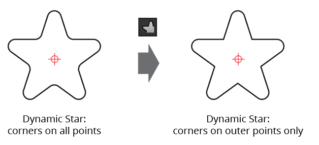
Dynamic Star Corner Setting
10. Slicing Section
This section controls the start and end values of slices that may be added to the seven standard shapes, as previously described in Dynamic Shapes Tool: Editing Existing Shapes. Similarly to the size controls, a standard “link” icon between the two input fields can be clicked to specify whether changing the start slice value simultaneously changes the end slice value, and vice versa.
By default, slice values are specified as angles in degrees, but using the preferences it can be changed to instead use percentage values (also measured in the clockwise direction starting at the top).
Option/Alt-clicking on either the start slice icon or the end slice icon is a shortcut for reversing the slice values (the start value becomes the end value, and vice versa):
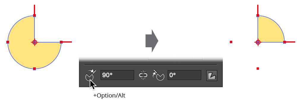
Dynamic Shapes Slice reversing
Adding Shift while Option/Alt-clicking duplicates the shape before reversing the slice values, which can be useful when making pie charts.
The button on the right side of the slicing section controls whether line segments are drawn to the center of the path from the slice perimeter, keeping the path closed. When turned off, these segments are not included, and the resulting path is an open path.
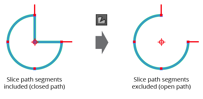
Dynamic Shapes Slice segments button
Illustrator Location:
Advanced Toolbar > Width Brush Tool
Width Brush is an Astute Graphics tool for Adobe Illustrator that allows you to edit variable width stroked paths by simply brushing them. It supports adjustment by fixed amounts or by percentage, and includes pressure support for tablet input devices. Width Brush is part of the WidthScribe plugin.

Width Brush in Action
Tool Location and Cursor Appearance
The Width Brush tool appears in Illustrator’s main toolbar (which must be in Advanced mode: View > Toolbars > Advanced).

Width Brush Tool Location
The Width Brush tool’s cursor is a crosshair surrounded by a gray circle which indicates the brush diameter. Small badges distinguish between fixed value and percentage modes. A caption will appear if no paths are selected:

Width Brush Cursors
Illustrator Location:
Illustrator Main Menu > Window > Astute Graphics > AG Block Shadow
AG Block Shadow is an Astute Graphics live effect that adds block shadows (also known as solid shadows) to paths, text, or placed images. Controlled by a panel and a tool, the shadows have many parameters which can be changed, such as the length, gap, and angle; whether to use a vanishing point; and whether the shadow picks up its color from the artwork or has an independent color. AG Block Shadow is part of the Stylism plugin.

AG Block Shadow Default Example
As with most live effects, AG Block Shadow appears in the main menu, under Effect > Stylism > AG Block Shadow. It can also be applied directly from the Appearance panel using the “Add New Effect” button at the bottom of the panel. However, easier ways to apply the live effect are by using the Apply button on the AG Block Shadow panel, or by clicking on an object with the AG Block Shadow tool.
Illustrator Location:
Illustrator Main Menu > Window > Astute Graphics > Dynamic Corners
The Dynamic Corners component of VectorScribe consists of the Dynamic Corners tool and the Dynamic Corners panel. While the tool can be used alone, additional functionality is accessed through the panel.
Dynamic Corners allows you to add corners (of three types, using three methods) to paths. These corners — unless the path is externally edited in a way that destroys their integrity — remain “live” and may be subsequently changed or removed. Corners created with the Rounded Corners live effect or with Illustrator’s native Live Corners (which was released almost three years after Dynamic Corners, and attempted to copy many of its features) may also be converted to Dynamic Corners. The corners on Standard Dynamic Shapes can also be edited with the Dynamic Corners tool.
For a description of the types and methods of corners, see Dynamic Shapes Panel: Overview, Corners Section.
Although they contain metadata, paths which include Dynamic Corners are still normal paths. Files with Dynamic Corners may be opened on a machine without VectorScribe installed without issues.
Illustrator Location:
Illustrator Main Menu > Window > Astute Graphics > Reform Text
Reform Text is a tool to place text on paths. It is intended as an alternative to the native Text on a Path tool. The main advantage is that it is easier to use and gives more intuitive control over text placement.
Reform Text’s functionality allows for:
Variable height text
Mirroring and reversing
Sharp corner control
Baseline placement
Control of the distortion as text flows over curved paths
When applied the text is distorted to match the curve of the control path, the glyphs are not simply rotated as some similar tools will output. It also allows for text to be bent to represent a curved surface, such as the label of a bottle.
Reform Text consists of a tool and an associated panel.
The Reform Text tool appears in Illustrator’s main toolbar (which must be in Advanced mode: View > Toolbars > Advanced) stacked under the native Text tool. As with other stacked tools, click and hold on the top tool icon to display the tools stacked under it.
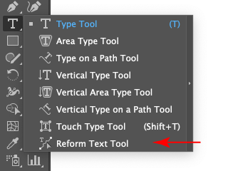
Reform Text Tool Location
You can also click on the Reform Text panel to activate the tool. To locate the Reform Text panel from the menu, go to Window > Astute Graphics > Reform Text. Initially all the controls will be greyed out. This is because Reform Text needs one Text Box object and one path to be selected before it can place the text on the path. When these two objects are selected, the Make button will become available. Clicking the Make button will activate the other controls, and the selected text should be placed on the selected path.
The Text Box object is not destroyed by this process, though it will not appear in the rendering of the artwork. The text remains editable until the art is expanded, at which point it turns into regular paths. The path also remains editable using the normal Illustrator tools.
Illustrator Location:
Advanced Toolbar > Dynamic Corners Tool
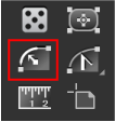
Dynamic Corners Tool Location
The Dynamic Corners tool is used to create new corners (either from scratch, or by converting existing non-dynamic corners), select existing corners, or edit existing corners. Its cursor is a solid, tail-less arrow. When the Dynamic Corner tool is in use, all Dynamic Corners in the document, except for those on hidden paths, are annotated. By default, the annotation consists of a small red circle at the radius point of the corner and (unless selected) a red arrow connecting the radius point to the center of the corner’s segment(s). This appearance can be changed in the preferences.
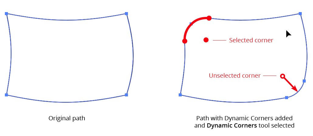
Dynamic Corner Overview Example
Illustrator Location:
Advanced Toolbar > Width Brush Stack > Width Eraser Tool
Width Eraser is a simple Astute Graphics tool for Adobe Illustrator that visualizes and removes width markers from variable width strokes using a brush-like interface. Width Eraser is part of the WidthScribe plugin.
Tool Location and Cursor Appearance
The Width Eraser tool appears in Illustrator’s main toolbar (which must be in Advanced mode: View > Toolbars > Advanced), stacked under the Width Brush tool. As with other stacked tools, click and hold on the top tool icon to display the tools stacked under it.
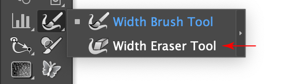
Width Eraser Tool Location
The Width Eraser tool’s cursor is a crosshair surrounded by a gray circle, which indicates its diameter. A caption will appear if no paths are selected:

Width Eraser Cursors
Illustrator Location:
Advanced Toolbar > Text Stack > Reform Text Tool
Text can be edited either from the Reform Text panel or by using the tool. Virtually all operations are available from both, but sometimes it is easier to work interactively with the cursor, and sometimes it is easier to enter values into the panel.
The delimiters can be moved by dragging them. To disable snapping to anchor points, hold down Command/Ctrl while dragging. To quickly move the delimiters so that the entire path is affected by the Reform Text tool, doubleclick either one of them. This will move them to the path's endpoints. If a delimiter is dragged such that a marker would fall outside of the newly-delimited portion of the path, the marker will be automatically deleted. If a marker is located exactly on a delimiter, then moving the delimiter will also move the marker.
Markers can be moved by dragging them within the delimited reshape extent. To disable snapping to the path's underlying anchor points, hold down Command/Ctrl while dragging. Dragging a marker by its circle annotation will allow you to freely change both its position along the path and its offset; to change only its offset, hold down Shift while dragging.
To change only its position, drag the marker's black line.
To select a single marker, click on its red annotation shape.
Multiple markers may be selected by Shift + clicking them or by dragging a marquee over them in the normal manner.
To delete a marker, doubleclick its red shape.
To create an additional marker, place the cursor over either the original or virtual reshaped path and click or click-and-drag.
To change a marker from smooth to sharp or vice versa while dragging it, press the X key.
When using the Reform Text tool, Astute Graphics’ AstuteBuddy panel should be kept open to show relevant keypresses.
Illustrator Location:
Illustrator Main Menu > Object > Path > Optimize/Vary Width Markers...
Optimize Width Markers and Vary Width Markers are Adobe Illustrator menu commands created by the WidthScribe plugin from Astute Graphics. The first allows you to reduce the number of width markers in a variable width stroke while changing its width profile as little as possible. The second allows the random addition of new width markers to create an organic look to path strokes.
Illustrator Location:
Illustrator Main Menu > Window > Astute Graphics > Dynamic Corners
The Dynamic Corners panel is used in conjunction with the tool to change existing corners, to set the parameters that will be used for new corners, and to access several utility functions. When the Dynamic Corners tool is not in use, the panel displays only a “Click to select” message; clicking anywhere on the panel selects the tool and displays all the controls.
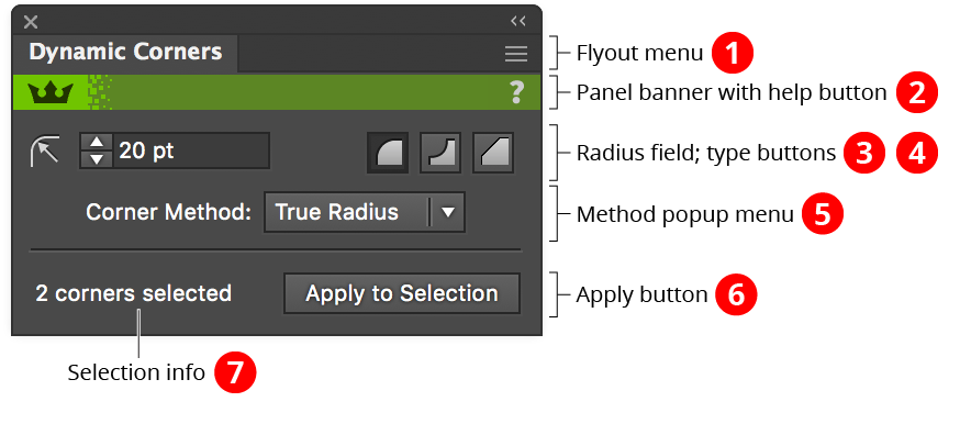
Dynamic Corners panel
1. Flyout menu
See Dynamic Corners Panel: Flyout Menu.
2. Panel banner
The help button on the right opens the help documentation in the Astute Manager. If this does not automatically appear, please ensure your Astute Manager is running first.
Click on the other area of the color bar to activate the Dynamic Corners tool. This is a quick method of locating the tool within the default Advanced toolbar or a custom toolbar.
3. Radius field
Specifies the radius of all selected corners, or for new corners created by clicking without dragging. If a corner cannot accommodate the specified radius, the radius will be made as large as possible.
Shift-clicking on the radius icon is a shortcut for choosing the flyout menu item Select All Corners on Selected Paths. Shift+Option/Alt-clicking on the radius icon is a shortcut for choosing the flyout menu item Convert to Dynamic Corners.
4. Type Buttons
Specifies the type of all selected corners, or for new corners created by clicking without dragging.
5. Method Popup Menu
Specifies the method of all selected corners, or for new corners created by clicking without dragging.
6. Apply Button
Applies corners (using the settings showing in the panel) to all eligible selected anchor points.
7. Selection Info
Displays the current number of selected Dynamic Corners.
Illustrator Location:
Illustrator Main Menu > Window > Astute Graphics > AG Offset
AG Offset is an Astute Graphics live effect which offsets paths like the native Offset Path live effect, but works correctly on open paths and offers many more options. These include the ability to create multiple offsets, offset from both sides of the path at once, change the stroke, fill, and opacity of the offsets, and offset grouped paths as if they were combined into a compound shape. Instead of a modal dialog, the effect’s parameters are adjustable using a panel, and a companion tool allows you to adjust the effect interactively. AG Offset is part of the Stylism plugin.
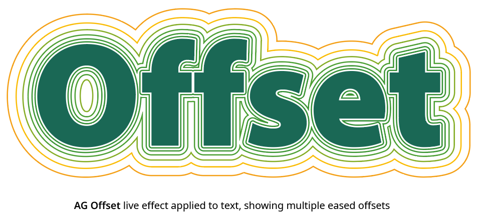
AG Offset Default Example
As with most live effects, AG Offset appears in the main menu, under Effect > Stylism > AG Offset. It can also be applied directly from the Appearance panel using the “Add New Effect” button at the bottom of the panel. However, easier ways to apply the live effect are by using the Apply button on the AG Offset panel, or by clicking on an art object with the AG Offset tool.
Illustrator Location:
Advanced Toolbar > Dynamic Measure Tool
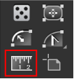
Dynamic Measure Tool Location
The Dynamic Measure tool is used to create, edit, delete, or convert measures. It has a cursor like a small crosshair. To make a measurement, click once at the start point and again at the end point (this method can be changed to click-and-drag in the preferences). The start and end points will be connected by a thin line (red by default), and an arrow showing the direction. Measurement values appear both in the Info panel and, by default, in a box next to the cursor.
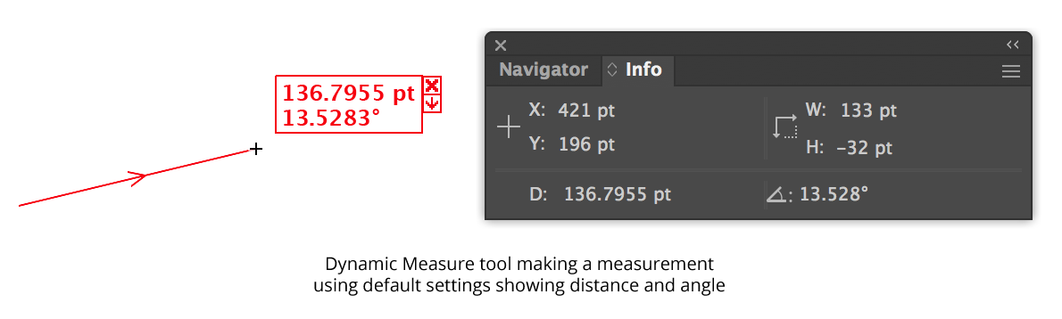
Dynamic Measure Overview
Information about the path under the cursor is also displayed by default, using a feature called “Hover Measure” (see below).
Illustrator Location:
Illustrator Main Menu > Window > Astute Graphics > Dynamic Measure
The Dynamic Measure panel is used in conjunction with the tool to change displayed parameters, change the scale and units, and measure the closest distance between two paths.
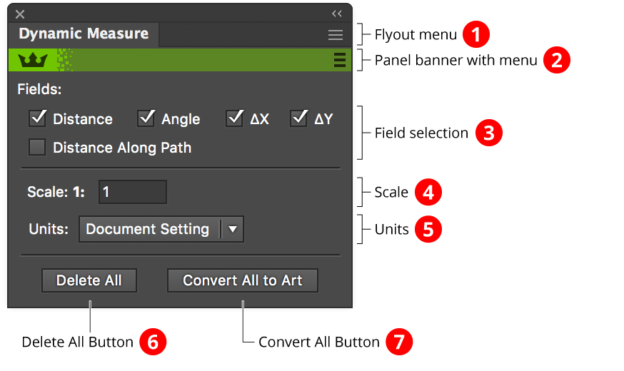
Dynamic Measure Panel Overview
1. Flyout menu
See Dynamic Measure Panel: Flyout Menu.
2. Panel banner
The help button on the right opens the help documentation in the Astute Manager. If this does not automatically appear, please ensure your Astute Manager is running first.
Click on the other area of the color bar to activate the Dynamic Measure tool. This is a quick method of locating the tool within the default Advanced toolbar or a custom toolbar.
3. Field Selection
Specifies which the fields which are displayed for each Dynamic Measure (existing and new). ∆X and ∆Y (also notated as dX and dY depending on the preferences) are the horizontal and vertical components of the measure. Distance Along Path is only valid when the measure starts and ends on a path.
4. Scale
Specifies the scale (multiplier) for displayed measurement values, between 0.000001 and 1,000,000. If, for example, you are creating a map with the scale of 1” equals 1 mile, the scale would be set to the number of inches in 1 mile (5280 × 12 = 63360).
5. Units
Specifies the units for displayed measurement values, from the following: Micrometers, Pixels, Points, Millimeters, Picas, Centimeters, Inches, Feet and inches, Meters, Kilometers, Miles and feet, and Miles (decimal). When set to “Document Setting”, the units will be picked up from the units used in the open document.
6. Delete All Button
Deletes all Dynamic Measures in the document. The Dynamic Measure tool does not need to be active.
7. Convert All Button
Converts all Dynamic Measures in the document to artwork. The Dynamic Measure tool does not need to be active.
Illustrator Location:
Illustrator Main Menu > Window > Astute Graphics > AG Layer Comps > Panel Flyout Menu
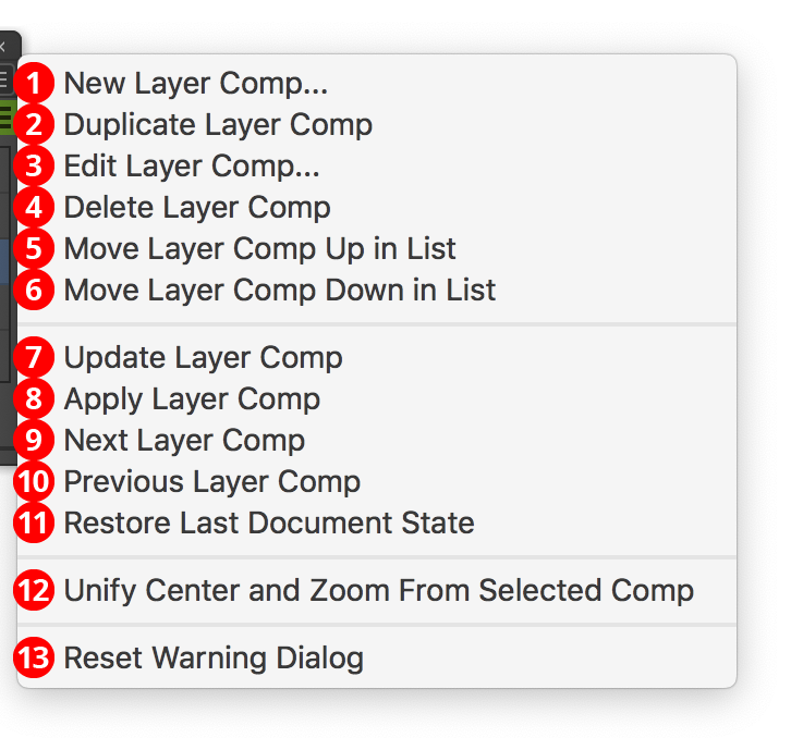
AG Layer Comps Panel Flyout Menu Callouts
The AG Layer Comps panel flyout menu items are contextually sensitive and all items may not be available, depending on the current layer comp selection. Most of the menu items replicate the operations of the buttons on the bottom of the panel.
1. New Layer Comp...
Does the same as the Create New Layer Comp button.
2. Duplicate Layer Comp
Makes a copy of the selected layer comp and places it at the bottom of the list.
3. Edit Layer Comp...
Does the same as double-clicking on a layer comp (see above).
4. Delete Layer Comp
Does the same as the Delete Layer Comp button.
5. Move Layer Comp Up in List
Does the same as the Move Up button.
6. Move Layer Comp Down in List
Does the same as the Move Down button.
7. Update Layer Comp
Does the same as the Update Layer Comp button.
8. Apply Layer Comp
Does the same as clicking on the “Apply Layer Comp” icon in the layer comp list for the selected layer comp.
9. Next Layer Comp
Does the same as the Next Layer Comp button.
10. Previous Layer Comp
Does the same as the Previous Layer Comp button.
11. Restore Last Document State
Does the same as clicking on the “Apply Layer Comp” icon in the layer comp list next to “Last Document State”.
12. Unify Center and Zoom From Selected Comp
Copies the view center and zoom level data from the selected layer comp to all other layer comps.
13. Reset Warning Dialog
If the “Broken Layer Comp” warning dialog has been suppressed using the Don’t show again checkbox, re-enables the dialog.
Illustrator Location:
Advanced Toolbar > PathScribe Stack > Extend Path Tool
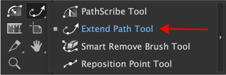
Extend Path Tool Location
By click-dragging on the end of an open path, the Extend Path tool can extend it (make it longer) or shorten it. Other selected open paths can optionally be simultaneously changed. Lengthening can be done in different ways, and the path’s length (or change in length) can be constrained to specific increments.
Illustrator Location:
Illustrator Main Menu > Window > Astute Graphics > Gradiator
Gradiator is an Astute Graphics panel for working with artwork containing linear or radial gradients. It includes several functions which are not available on the native Gradient panel, such as numerically setting the origin or length of a gradient; changing the angle of multiple gradients; capturing a gradient including its absolute position and applying it to one or more paths; and rotating or randomizing the color order of one or more gradients’ stops. Additionally, it includes three specialty functions, including converting flat color fills and strokes to gradients and vice versa. Gradiator is part of the SubScribe plugin.
Illustrator Location:
Advanced Toolbar > PathScribe Stack > Extend Path Tool
To use the Extend Path tool, place its cursor near the start or end of an open path (the path does not need to be selected). The cursor will change from a small crosshair to a tail-less arrow, and small lines (red, by default) will appear at the start and end of the path, perpendicular to it, which will dynamically indicate the start and end limits of the path during the drag.
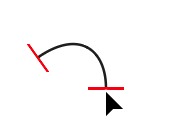
Extend Path Tool Hovering end point
To edit the path, hold the mouse button down. Now a pair of gray lines will appear, indicating how the path would be extended (in both directions), given the current extension mode and parameters. By default, the current length of the path and its change in length will be displayed next to the cursor. The small red square indicates that the Extend Path tool is snapping to an anchor point (here, the endpoint of the original path).
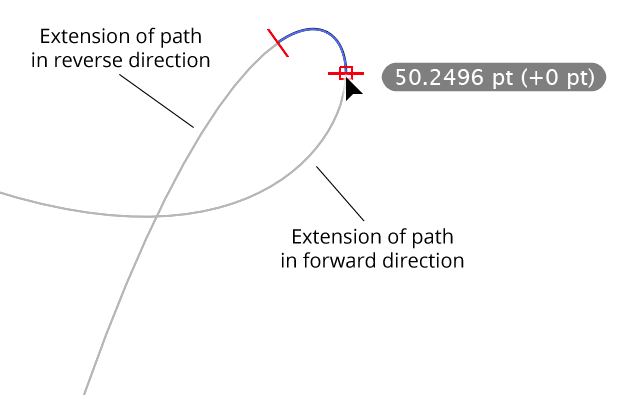
Extend Path Bezier extension complete
Dragging the cursor along the extension preview will move whichever limit line was clicked on, showing the virtual new endpoint of the path. The cursor does not need to be kept directly above the extension preview, as the limit line will snap to the nearest position on the line. Releasing the mouse button finalizes the edit.
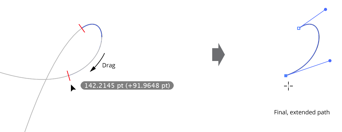
Extend Path Dragging the cursor along the extension preview
During the drag, by default, the cursor will snap to intersections of the extended path to other paths (or to the extended path itself); this will be indicated by a small circle around the limit line:
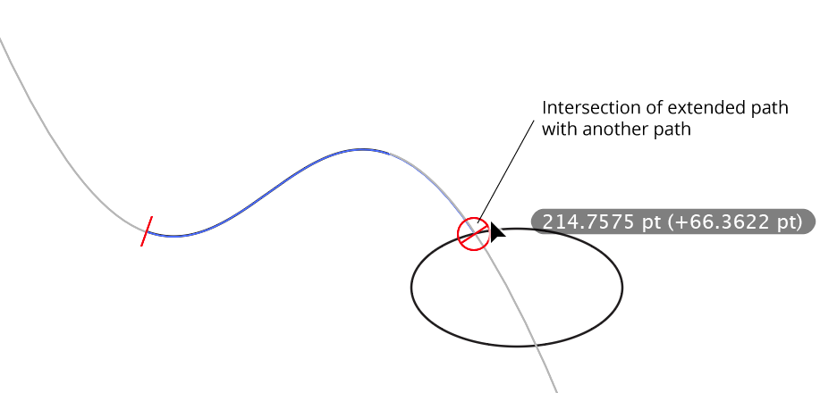
Extend Path Bezier Extension Intersection
Dragging backwards into the existing path will shorten it:
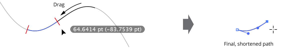
Extend Path Shortening Example
Note: If you drag from the final point of an open path, but then move the cursor so it is over the extension preview that comes from the first point of the path, the path will be extended in the reverse direction but the entire original portion of the path will be removed, as this is equivalent to shortening the path to zero length before starting to re-extend it.
Illustrator Location:
After selecting the Smart Remove Brush tool, first adjust its size (either through the preferences dialog or by using the keys assigned to “Increase Tool Diameter” and “Decrease Tool Diameter” in Illustrator’s Keyboard Shortcuts dialog, just as with other brush tools). The circle surrounding the crosshair cursor reflects the current size of the brush.
To use the tool on a path, simply brush over the areas of the selected path(s) where you want to remove anchor points. Each path’s new virtual shape is continually displayed in red, allowing you to see how much it has changed with the removal of the points.
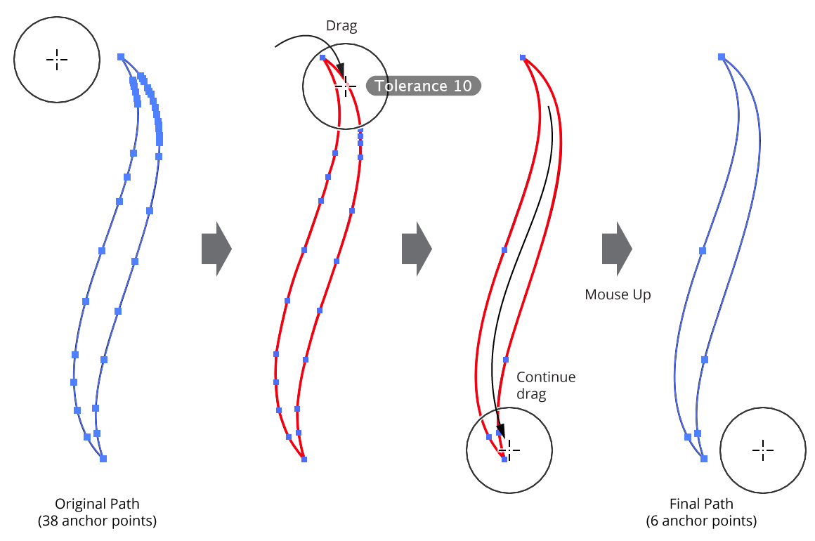
Smart Remove Brush Tool Overview
For each anchor point that falls within the brush circle, the tool decides based on its current parameters whether it will be removed or not (in all cases, when a point is removed, the path’s geometry is kept as close to the original as possible). First, if an anchor point is selected, and the Shift key is being held down, the point is considered protected and is never removed. Second, if the Command/Ctrl key is being held down, the point is always removed in a “non-smart” manner (i.e., surrounding handles are not adjusted).
Then, if the Ignore Tolerance preference is enabled, the point is always removed. Otherwise, the amount of distortion that would result if the point were removed is calculated and compared to the current tolerance value. If the amount is below the tolerance value, the point is removed.
It is best to start with a low tolerance value and slowly increase it if the path still has too many anchor points. The default tolerance of value of 10 generally works well with most paths, but higher values can aggressively remove more anchor points when exact path geometry is not critical.
While dragging the Smart Remove Brush tool, several keys may be pressed to change parameters on the fly or change functionality. As with all Astute tool keypresses, these will be indicated on the Astute Buddy panel.
Shift: Protects selected points (keeps them from being removed). This is useful for preserving specific anchor points without having to carefully dodge around them with the brush:
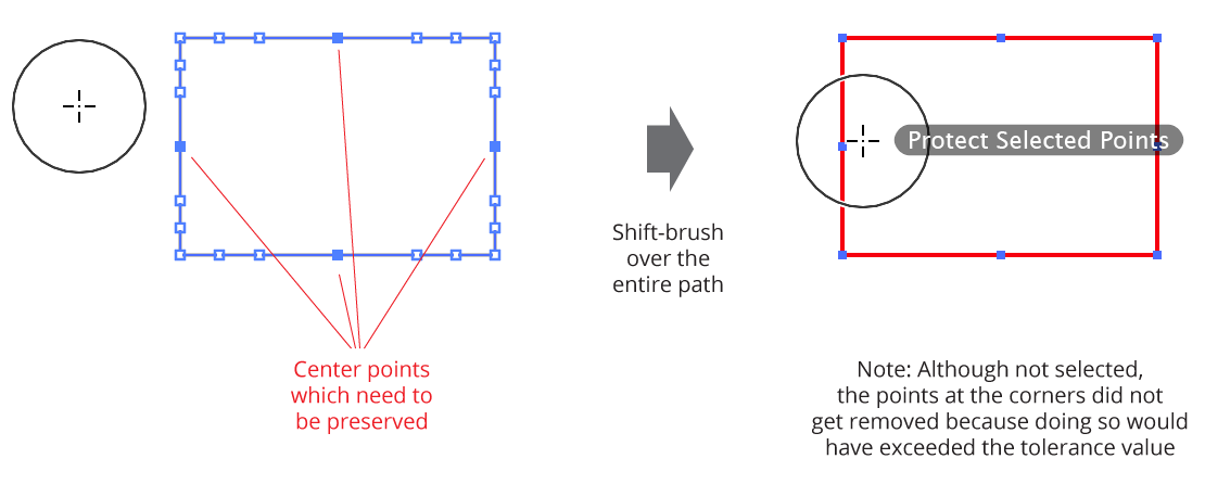
Smart Remove preserving specific anchor points
Option/Alt: Temporarily inverts the Ignore Tolerance preference. That is, if Ignore Tolerance is disabled (tolerance is being used), and the
Option/Altkey is pressed, the tool will temporarily ignore the tolerance value, removing any anchor points which fall within the brush circle regardless of how it causes the path geometry to change. This can be useful, in conjunction with theSkey (see below), for “forcing” a point to be removed.Command/Ctrl: Forces the tool to remove points in a “non-smart” way (i.e., it simply removes the points without adjusting handles in an attempt to retain path geometry).
Space: Hides the annotations.
Up Arrow/Down Arrow: Changes the tolerance value, from 1 to 100. Anchor points which have already been brushed over and are no longer in the brush circle will not be re-evaluated when the tolerance value is changed on the fly, allowing you to brush different areas of a path with different tolerances.
Left Arrow/Right Arrow: Changes diameter of the brush, from 1 pixel to 2500 pixels. The “Increase/Decrease Tool Diameter” keys can also be used.
S: Temporarily changes the brush size to a small value (19 pixels). This is useful when used in conjunction with
Option/Alt(see above) for forcing the smart removal of specific points regardless of the current tolerance value.
Illustrator Location:
Illustrator Main Menu > Window > Astute Graphics > Gradiator > Panel Flyout Menu
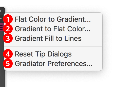
Gradiator Panel Flyout Menu
The Gradiator panel flyout menu items are contextually sensitive and all items may not be available, depending on the current selection.
1. Flat Color to Gradient...
See Gradiator Panel Flyout Menu: Flat Color to Gradient
2. Gradients to Flat Color...
See Gradiator Panel Flyout Menu: Gradients to Flat Color
3. Gradient Fill to Lines
See Gradiator Panel Flyout Menu: Gradient Fill to Lines
4. Reset Tip Dialogs
If one or more of Gradiator’s tip dialogs have been suppressed using the Don’t show again checkbox, clicking this button will re-enable them.
5. Gradiator Preferences
Illustrator Location:
Advanced Toolbar > PathScribe Stack > Reposition Point Tool
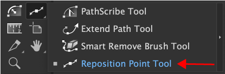
Reposition Point Tool Location
The Reposition Point tool allows you to “slide” one or more selected points along a path while maintaining the path’s original shape as closely as possible. The shifted points snap to 45° tangencies. The tool can also marquee select, add, and remove points from paths.
Illustrator Location:
Advanced Toolbar > PathScribe Stack > Reposition Point Tool
To reposition an anchor point, it must be selected first. Although this can, of course, be done with any selection tool, the Reposition Point tool itself can be used to marquee-select anchor points. Then, simply drag the anchor point(s) to a new position along the path. While dragging, the new shape of the path is displayed in red, so you can see how much the path geometry may have changed. Positions along the path where the tangent angle equals any of the 45° increments around the general constrain angle are highlighted with magenta dots, and the repositioned point will snap to these positions, displaying a red guide which is the tangent line.
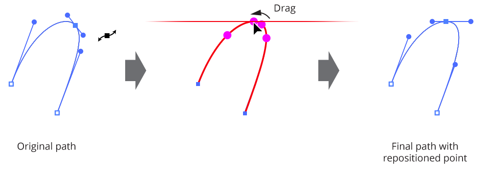
Reposition Point Tool Overview
To suppress the tangency snapping, Command/Ctrl can be pressed while dragging. The Space bar can also be pressed, to suppress all annotations.
If an endpoint of an open path is selected, it will be ignored, since it cannot be moved.
Illustrator Location:
Illustrator Main Menu > Window > Astute Graphics > Gradient Forge
Gradient Forge is an Astute Graphics panel for editing a single linear or radial gradient. It addresses several shortcomings of the native Gradient panel, including its inability to select and operate on multiple stops or midpoints; the lack of stop snapping to integer values while dragging; its inability to see or select stops that lie directly under others; and its inability to tell at a glance whether a stop has a custom color or opacity set. Additionally, Gradient Forge includes functions to create new gradients directly from artwork or swatches. Gradiator is part of the SubScribe plugin.
Illustrator Location:
Illustrator Main Menu > Window > Astute Graphics > Gradient Forge
Menu items to show and hide the Gradient Forge panel can be found in the main menu under Window > Astute Graphics > Gradient Forge.
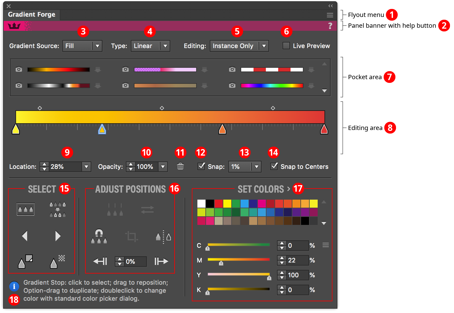
Gradient Forge Panel
1. Flyout Menu
See Gradient Forge Panel: Flyout Menu.
2. Panel Banner
The help button on the right opens the help documentation in the Astute Manager. If this does not automatically appear, please ensure your Astute Manager is running first.
3.4.5.6. Source, Type, Editing and Preview
See Gradient Forge Panel: Source, Type, Editing and Preview.
7. Pocket Area
See Gradient Forge Panel: Pocket Area.
8. Editing Area
See Gradient Forge Panel: Editing Area.
9.10. Location and Opacity Values
See Gradient Forge Panel: Location and Opacity Values.
11.12.13.14. Snapping and Deleting
See Gradient Forge Panel: Snapping and Deleting.
15. Select Section
See Gradient Forge Panel: Select Section.
16. Adjust Positions Section
See Gradient Forge Panel: Adjust Point Section.
17. Set Colors
See Gradient Forge Panel: Set Colors/ Adjust Colors Section.