 Dynamic Shapes Panel
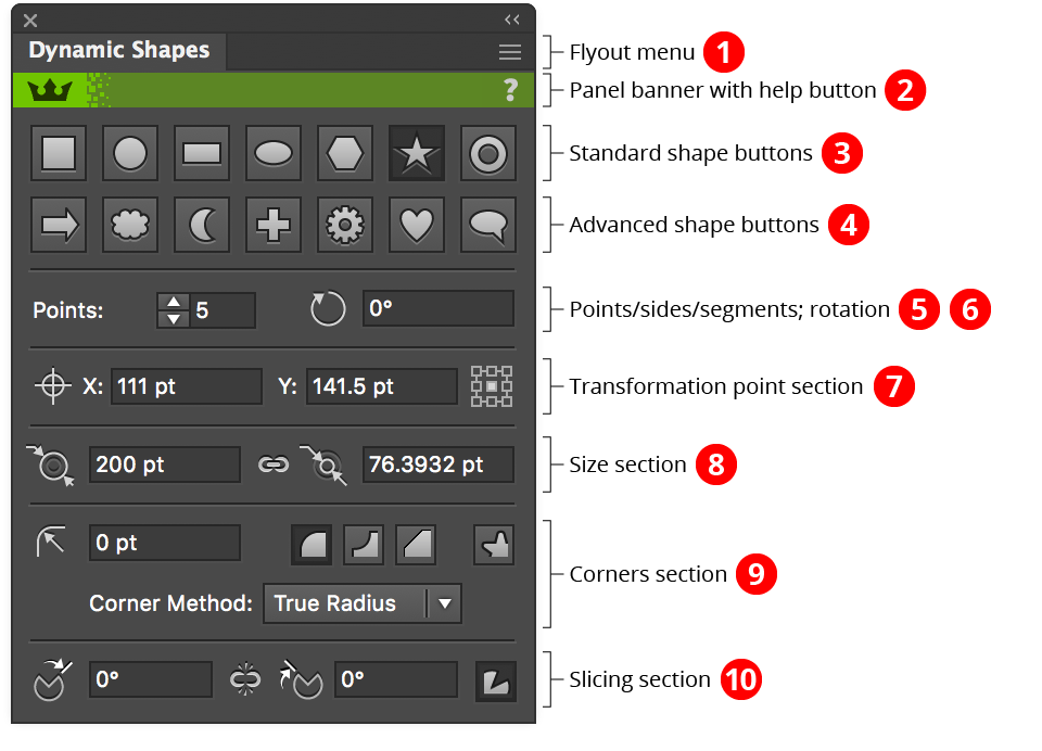
The Dynamic Shapes panel is used in conjunction with the tool to change existing shape types; to set shape parameters numerically (including parameters which can’t be changed using the tool alone); and to access several utility functions. When the Dynamic Shapes tool is not in use, the panel displays only a “Click to select” message; clicking anywhere on the panel selects the tool and displays all the controls.
Dynamic Shapes Panel Overview
1. Flyout menu
See Dynamic Shapes Panel: Flyout Menu.
2. Panel banner
The help button on the right opens the help documentation in the Astute Manager. If this does not automatically appear, please ensure your Astute Manager is running first.
Click on the other area of the color bar to activate the Dynamic Shapes tool. This is a quick method of locating the tool within the default Advanced toolbar or a custom toolbar.
3. Standard Shape Buttons
4. Advanced Shape Buttons
By default, standard shapes are shown on a separate row from the advanced shapes. This can be changed in the preferences to make the panel shorter; when all the shape buttons are shown in a single row, arrow buttons can be used to switch to the beginning and end of the row:
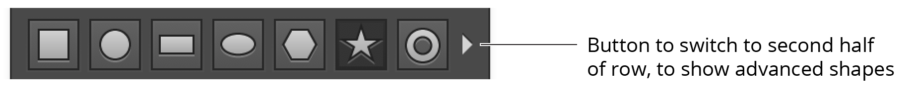
Dynamic Shapes Single panel shape row
Clicking on a shape button changes all selected Dynamic Shapes to the chosen type, altering any other parameters only when necessary (for example, a square being turned into a star may have corners larger than the star can support; in this case, the corner radii will be changed to the maximum value that the star can accommodate).
5. Points/Sides/Segments Value
When the shape supports a variable number of points, sides, etc., this control is enabled and allows you to change the value, between a minimum of 3 and a maximum of 1000.
6. Rotation value
Allows changing the rotation of all selected shapes. Dynamic Shapes measures rotation values with zero degrees pointing up, and positive values increasing a clockwise direction.
7. Transformation Point Section
A Dynamic Shape’s transformation point is the point relative to which rotation and scaling are done. The coordinates of the transformation point may be specified numerically, and the location of the point (relative to the shape’s bounding box) can be changed by picking of the nine standard positions using the control on the right. When multiple shapes with different transformation point locations are selected, or when the transformation point has been moved to a custom position using the tool, none of the locations on the control will be highlighted.
By holding down Option/Alt when clicking to change the transformation point location, the Dynamic Shape will be moved relative to the point, rather than the point moving.
8. Size Section
Some Dynamic Shapes have their size specified by only a single dimension (width/outer diameter). These include the square, circle, polygon, cloud, and crescent. All other shapes have a second, independent dimension: height or inner diameter. A standard “link” icon between the two input fields can be clicked to specify whether changing one dimension will also change the other (which is done proportionally). Polygons may have their outer diameter or side length specified, but these are not independent sizes. Sizes may range from 0 to 16384 pt.
Shift+Command/Ctrl-clicking on the link icon is a shortcut which can be useful after converting native art to rectangles and ellipses. It rotates the shape 90° counterclockwise (add Option/Alt for clockwise rotation) but simultaneously swaps the width and height parameters, so the rotated art looks the same.
9. Corners Section
This section controls the corners that may be added to the seven standard shapes. Corners may be one of three types: Regular (a curve facing outwards); Negative (a curve facing inward); or Chamfered (a straight line cutting across the corner).
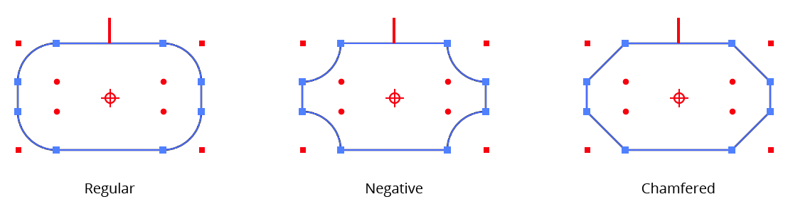
Dynamic Shape corner types
The corner type buttons on the Dynamic Shapes panel change the type of all of the shape’s corners. To change the type of only one corner, use the Dynamic Corners tool to select and edit it.
For corner types with curves (i.e., Regular and Negative), you may also specify the method used to create the curve by choosing it from the popup menu. A Dynamic Shape can only have one corner method, shared by all corners.
True Radius method corners are created with one or two circular segments and maintain a constant radius as closely as is possible using the cubic bezier curves with which all Illustrator paths are constructed.
Standard method corners are the type that the native “Round Corners” live effect creates. When placed on a right angle, they are identical to True Radius corners, but at other angles they are of non-constant radii, the values of which vary substantially from the nominal radius value.
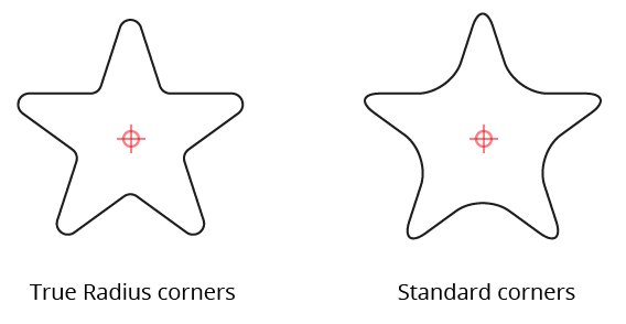
Dynamic Shapes Standard corner methods
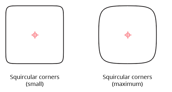
Squircular method corners approximate the “Squircle” curve popularized by Apple. A squircle is a blend between a square and a circle. These non-constant-radius corners feature a smoother transition between the curved section and the straight section of path, and are most useful on the right angles of squares and rectangles.
It may seem meaningless to to apply a “corner” to a circle or ellipse, and indeed, Regular corners have no effect on the appearance of these shapes (although they do add extra anchor points). However, using Negative or Chamfered corners allows the creation of some potentially useful geometry:
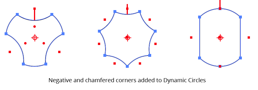
Dynamic Shapes Negative Chamfered Corners
The radii of corners on a Dynamic Shape cannot be increased beyond the point when one of their endpoints reaches the midpoint of one of the two adjacent segments, even if it might have space to go past this point. To enlarge a corner past this limit, you must remove the shape’s dynamic status (see Dynamic Shapes Panel: Flyout Menu) and use the Dynamic Corners tool to edit the corner.
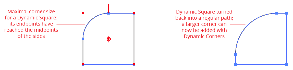
Dynamic Shape corner size limits
Dynamic Star shapes have one additional setting that is controlled by the button on the right side of the corners section of the panel. It determines whether or not a Dynamic Star’s corners appear on all of its points (both inner and outer), or only the outer points:
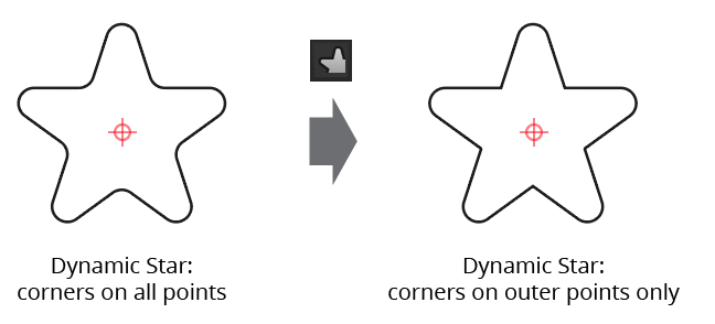
Dynamic Star Corner Setting
10. Slicing Section
This section controls the start and end values of slices that may be added to the seven standard shapes, as previously described in Dynamic Shapes Tool: Editing Existing Shapes. Similarly to the size controls, a standard “link” icon between the two input fields can be clicked to specify whether changing the start slice value simultaneously changes the end slice value, and vice versa.
By default, slice values are specified as angles in degrees, but using the preferences it can be changed to instead use percentage values (also measured in the clockwise direction starting at the top).
Option/Alt-clicking on either the start slice icon or the end slice icon is a shortcut for reversing the slice values (the start value becomes the end value, and vice versa):
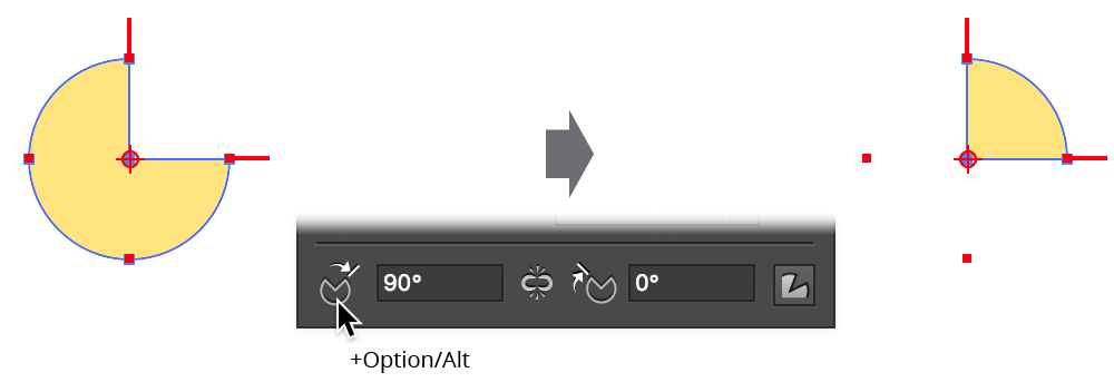
Dynamic Shapes Slice reversing
Adding Shift while Option/Alt-clicking duplicates the shape before reversing the slice values, which can be useful when making pie charts.
The button on the right side of the slicing section controls whether line segments are drawn to the center of the path from the slice perimeter, keeping the path closed. When turned off, these segments are not included, and the resulting path is an open path.
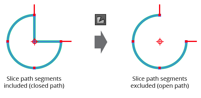
Dynamic Shapes Slice segments button
Dynamic Shapes Panel Flyout Menu
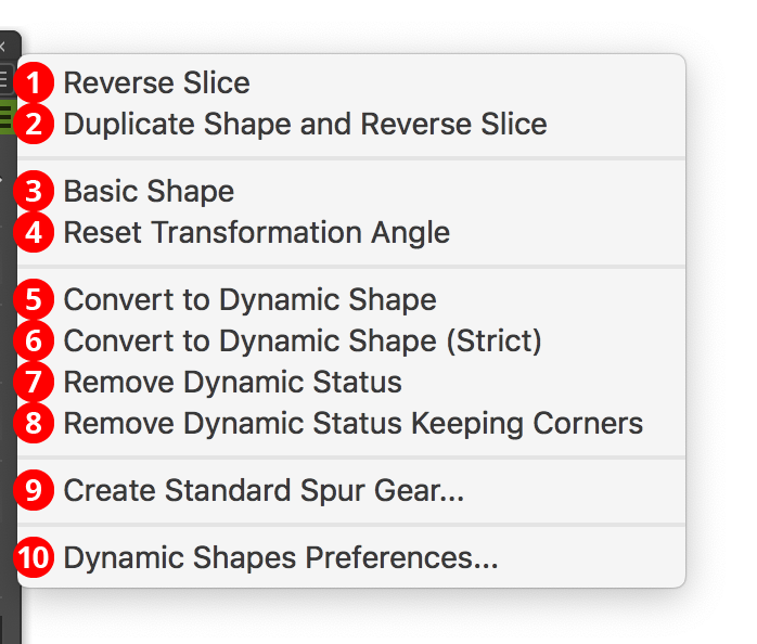
Dynamic Shapes Flyout Menu
1. Reverse Slice
Reverses the slice values (the start value becomes the end value, and vice versa). Any selected Dynamic Shapes are modified. The shortcut for this menu item is to Option/Alt-click on one of the slicing icons in the panel.
2. Duplicate Shape and Reverse Slice
Same as “Reverse Slice”, but duplicates the selected Dynamic Shape(s) before reversing the slicing values. The shortcut for this menu item is to Shift+Option/Alt-click on one of the slicing icons in the panel.
3. Basic Shape
Makes the selected Dynamic Shape(s) “basic.” This resets the shape to its default appearance: corners are removed, the aspect ratio (if applicable) is reset to its default value, and the number of segments, sides or corners is reset (for example, circles are given four segments; stars are given five corners, and polygons are given six sides). Standard shapes have any slicing removed, and advanced shapes have other parameters reset to their defaults. The shape’s position, size and angle are not changed.
4. Reset Transformation Angle
Changes the rotation of any selected Dynamic Shapes to zero degrees.
5. Convert to Dynamic Shape
6. Convert to Dynamic Shape (Strict)
Converts the selected ordinary paths (when possible) into Dynamic Shapes. If no paths are selected, all unlocked and unhidden paths in the document are considered. The “Strict” version differs in that the path geometry must be closer to “ideal” for conversion to occur than the non-Strict version, which uses a higher tolerance. When possible, the starting point of the Dynamic Shape’s path is matched with the starting point of the original path, which may lead to unexpected rotation angles.
Only standard (top-row) shapes can be converted. Sliced shapes (except in the case of circular arcs, which are converted to sliced circles) and shapes with negative or chamfered corners cannot be converted.
7. Remove Dynamic Status
8. Remove Dynamic Status Keeping Corners
Changes any selected Dynamic Shapes back into ordinary paths by discarding all meta-data that they contain. This can be useful to allow editing by the Dynamic Corners tool to create corners that are larger than the limit imposed when the corner is on a Dynamic Shape. The “Keeping Corners” version retains all existing corners, allowing them to be immediately edited by the Dynamic Corners tool.
9. Create Standard Spur Gear...
Brings up a dialog allowing you to create a Dynamic Gear that has its parameters set to resemble as closely as possible a realistic spur gear. Tooth count can be specified from 8 to 60. Circular pitch is the distance from tooth to tooth around the gear’s pitch circle; two gears with the same circular pitch will mesh precisely.
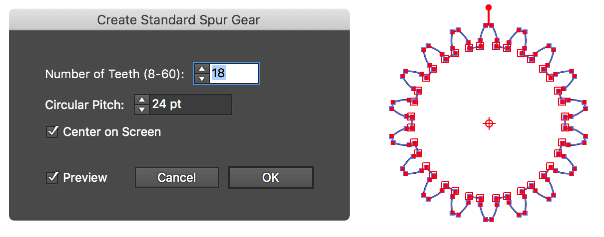
Dynamic Shape Create a standard spur gear
10. Dynamic Shapes Preferences...
Brings up the Preferences dialog (see Dynamic Shapes Preferences).