Shapes
 Circle by Points Tool
 Dynamic Shapes Tool
![]() AG Utilities Live Effects
AG Utilities Live Effects
Illustrator Location:
Advanced Toolbar > Circle by Points Tool
As the Circle by Points tool has several keypresses which can add or change its functionality, we suggest installing the free Astute Graphics plugin Astute Buddy, which creates a panel that dynamically updates to inform you of the various keys which can be pressed in the tool’s current context.
There are several methods of creating circles, depending on the Third Point Must Be Dragged tool preference (see Circle by Points: Preferences).
When the preference is enabled (the default), circles can be created from two points simply by clicking twice (allowing you to scroll, zoom, change the view mode, etc. in the middle of the operation), although they can also be created by clicking-and-dragging. The two points always define the diameter of the circle.
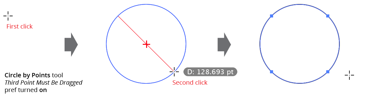
Circle by Points 2 Click Operation
To create a circle from three points, you must not release the mouse button after clicking to create the second point; instead you must start dragging, which positions the third point.
When the preference is disabled, circles can be created from three points by clicking three times. However, to create a circle from two points you must either click-and-drag from the first point, or doubleclick on the second point instead of single click.
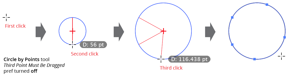
Circle by Points Tool 3 Click Operation
By default, the circle’s center, radii, and diameter value will be displayed while creating the circle, but these can be turned on and off independently through the preferences, as can the color of the annotation lines.
While creating a circle using two points, two modifier keys can be used with the Circle by Points tool:
Shift: Constrains the angle between the first point and the second point to increments of 45° around the constrain angle.
Option/Alt: Constrains the diameter of the circle to “nice” values, dependent on the current zoom level and units. For example, at 200% zoom, the diameter is constrained to multiples of 2 pt or 0.5 mm.
While creating a circle using three points, as the third point approaches the imaginary line formed by the first two points, the resulting circle approaches infinite size. When its size becomes larger than Illustrator could accommodate, the tool will no longer create artwork but will instead display “Circle too large” by the cursor. In this case, the third point must be moved to a different position.
The Circle by Points tool honors Smart Guides.
Illustrator Location:
Advanced Toolbar > Dynamic Shapes Tool
Dynamic Shapes can be created with the tool in three ways: by doubleclicking the artboard, by click-and-dragging on the artboard, or by converting an existing ordinary path (typically drawn with one of Illustrator’s native shape tools) into a Dynamic Shape.
Doubleclicking
Doubleclicking creates a new shape with its transformation point positioned at the location that was doubleclicked. The shape’s type, rotation, size, and any other parameters are taken from the panel settings, which are picked up from the previous created or edited shape. The shape must be subsequently edited in a separate step.
Dragging
When dragging to create a new shape, there are two methods you can use, depending on the Define New Shapes by Bounding Box preference:
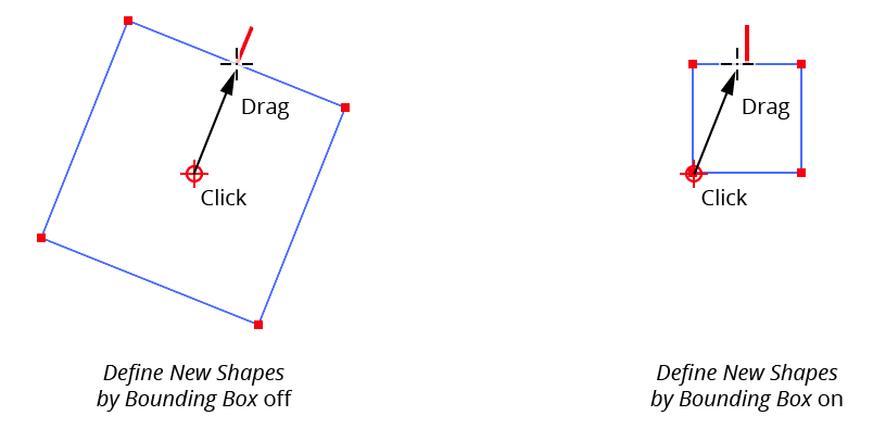
Dynamic Shape Creation
In both cases the transformation point is placed at the initial-click location. However, when the preference is turned off (“Draw from Center”), the transformation point becomes the shape’s center; the shape’s size is determined by the distance from the cursor to the clicked point, and the shape’s rotation is determined by the angle from the cursor to the clicked point.
When the preference is turned on (“Draw from Edge”), the transformation point becomes one of the four corners of the bounding box of the shape (which corner depends on drag direction); the shape’s size is determined by the horizontal and vertical offsets of the cursor, and the shape’s rotation is always set to the overall constrain angle.
When drawing shapes with independent widths and heights (such as rectangles, ellipses, crosses), the Bound Box method of drawing is usually more intuitive.
The Define New Shapes by Bounding Box preference can be changed any time during the drag by pressing the S key.
In addition to S, there are a number of other keypresses which can be used while drag-creating a shape. We recommend keeping the Astute Buddy panel open for easy reference.
Shift: Constrains the angle of the shape to 45° increments around the general constrain angle (not applicable when drawing from the edge).
Option/Alt: Allows adjustment of the shape’s corners (for standard shapes which have corners). When
Option/Altis held down, moving the cursor changes the corner radii rather than the shape’s size. WhenOption/Altis released, any corners are retained and cursor motion returns to changing the shape’s size.Command/Ctrl: Unlocks the shape’s aspect ratio, when applicable. For example, when drawing a Dynamic Rectangle (with Bounding Box off), the ratio between the width to height is initially set to whatever value was used previously; as the rectangle gets bigger, this ratio is maintained. But when
Command/Ctrlis pressed, the cursor’s motion only affects the rectangle’s width, thereby changing the aspect ratio. Likewise, when drawing a Dynamic Donut,Command/Ctrlchanges only the outside diameter rather than both diameters in proportion:
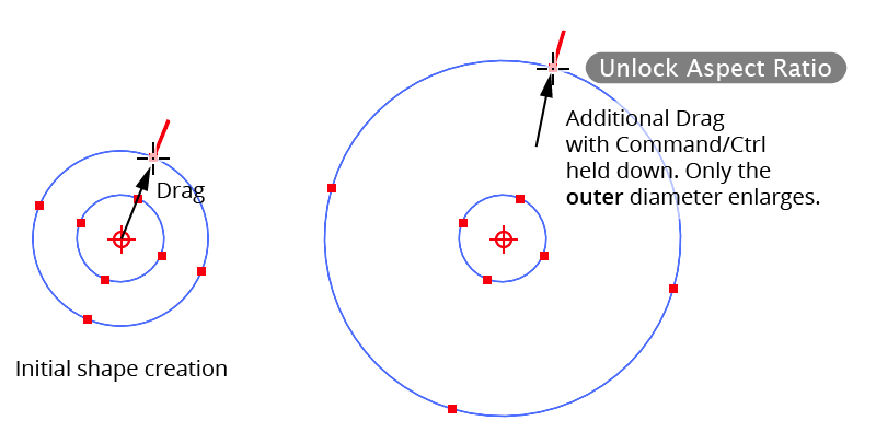
Dynamic Shapes Creation Aspect Ratio
Space: Moves the entire shape without changing its size or rotation.
Up Arrow/Down Arrow: For circles, ellipses, polygons, and donuts, changes the number of sides/corners. For arrows, changes the tip angle. For clouds, changes the puffiness. For crescents, changes the outer circumference fraction. For crosses, changes the offset. For gears, changes the tooth count. For hearts, changes the depth. For speech bubbles, changes the tail height.
Left Arrow/Right Arrow: For standard shapes, changes the corner radii. For arrows and crosses, changes the thickness. For clouds, changes the type. For crescents, changes the inner fraction. For gears, changes the tooth height. For hearts, changes the point value. For speech bubbles, changes the tip position.
1 through 7: Changes the type of shape directly to one of the seven basic types displayed on the top row of buttons on the Dynamic Shapes panel (where
1equals square,2equals circle, etc).9: Changes the type of shape to the previous type, as displayed on the Dynamic Shapes panel. For example, when drawing a Dynamic Gear, pressing
9would change the shape to a Dynamic Cross.0: Changes the type of shape to the next type, as displayed on the Dynamic Shapes panel. For example, when drawing a Dynamic Gear, pressing
0would change the shape to a Dynamic Heart.B: Makes the shape “basic.” This resets the shape to its default appearance: corners are removed, the aspect ratio (if applicable) is reset to its default value, and the number of segments, sides or corners is reset (for example, circles are given four segments; stars are given five corners, and polygons are givensix sides). Standard shapes have any slicing removed, and advanced shapes have other parameters reset to their defaults. The shape’s size and angle are not changed.
C: For standard shapes which have corners, changes the corner type (Regular, Negative, or Chamfered). If the corner radius is set to zero, no change will be immediately visible.
R: For Dynamic Stars with at least five points, adjusts the aspect ratio so that sides on either side of each arm are parallel.
U: Temporarily disables Smart Guides, if they were enabled when the drag started.
X: Toggles “Shape Replace,” if applicable. Shape Replace is available when a single path (or compound path) is selected before starting to draw a new Dynamic Shape. When enabled, the geometry of the existing path will be replaced by that of the drawn shape, while not affecting the path’s style, stacking order, group membership, etc.
Converting
The Dynamic Shapes tool can convert an ordinary Illustrator path into a Dynamic Shape (assuming its geometry is correct) by placing the cursor over the path. If the shape is able to be converted, an annotation next to the cursor will show “Shape Recognized” and annotations (in green) will be drawn over the shape. Clicking then finalizes the conversion of the shape.
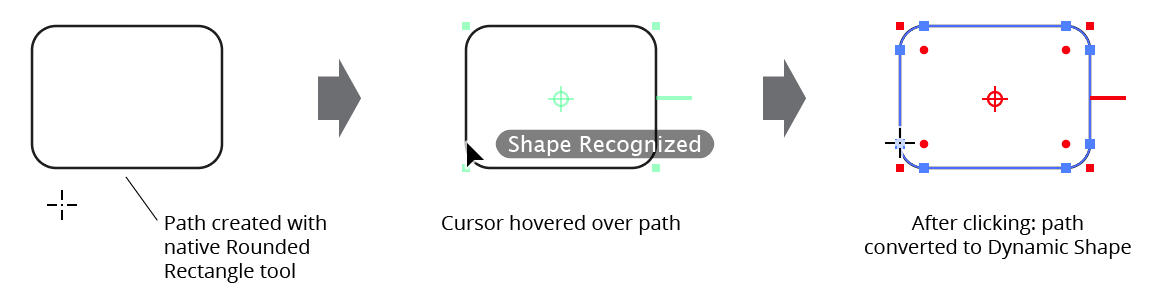
Dynamic Shape Recognition
When converting paths to shapes, Dynamic Shapes keeps the starting point of the path in the same spot when possible, which may lead to unexpected rotation angles. A quick way to fix this issue is addressed later (see Dynamic Shapes Panel: Size Section). To convert multiple paths into Dynamic Shapes in one step, use the panel flyout menu item (see Dynamic Shapes Panel: Flyout Menu).
Illustrator Location:
Advanced Toolbar > Dynamic Shapes Tool
The Dynamic Shapes tool can be used to select existing Dynamic Shapes in two ways. The first way is to simply click on the shape’s transformation point, path, or, for filled shapes, any part of the path’s filled area; holding down Shift will add the shape to the selection. The second way is to use the tool to drag-marquee. To do this, hold down Shift+Option/Alt and, starting at an empty area of the canvas, drag to marquee select art. Holding down Shift alone will add any marqueed art to the selection; holding down Option/Alt alone will remove any marqueed art.
Illustrator Location:
Advanced Toolbar > Dynamic Shapes Tool
The Dynamic Shapes tool edits existing shapes by clicking and dragging on the various control annotations that each shape displays. Below, functionality is described from the perspective of editing a single shape, but multiple Dynamic Shapes may of course be edited simultaneously. When the Dynamic Shapes cursor is over an annotated control, the cursor will change from a crosshair to a solid, tail-less arrow.
Additionally, when a Dynamic Shape is selected which supports a variable numbers of segments, sides or corners, the “Decrease Diameter” and “Increase Diameter” keys may be used to change this value, even when the mouse button is up. These keystrokes are set in Illustrator’s “Keyboard Shortcuts” dialog; by default, they are the left and right square bracket keys [ ] respectively.
Transformation Point Edits
Clicking
Selects the shape and deselects everything else. If Shift is held down, previously-selected objects will not be deselected first.
Doubleclicking
Resets the transformation point’s position to the center of the shape.
Dragging
Moves the Dynamic Shape. Other selected, non-Dynamic Shape art is not moved. When Smart Guides are off, the transformation will still snap to anchor points and other shapes’ transformation points. While dragging, several keys can be pressed to modify functionality:
Shift: Constrains the movement of the shape to 45° increments around the general constrain angle.
Option/Alt: Duplicates the shape to the new location.
Command/Ctrl: Moves the transformation point within the shape’s bounding box without moving the shape.
D: Toggles Duplicate Shape mode. When enabled,
Option/Altdoes not need to be held down to duplicate the shape.U: Temporarily disables Smart Guides, if they were enabled when the drag started.
Size Control Edits
The small, filled square annotations on selected Dynamic Shapes are size controls. In general, they appear at the positions of the shape’s anchor points (if corners were absent). Note: some advanced shapes have special controls which change a different parameter of the shape; by default, they appear as a size control surrounded by a second unfilled square:
Dynamic Shapes size control edits
Dragging
Dragging a size control with the Dynamic Shapes tool changes the size of the shape by scaling it up or down relative to its transformation point. If the shape has corners, the corner radii are not changed unless Shift is held down (see below) or the shape becomes so small that corners of the original radii are no longer possible. If multiple shapes are selected, scaling is proportional. In other words, scaling the shape under the cursor by 75% will cause all selected Dynamic Shapes to be scaled by 75% and so on. While dragging, several keys can be pressed to modify functionality:
Shift: For standard shapes, scales any corners along with the shape itself.
Option/Alt: For standard shapes, defines the corner radii; cursor motion makes the corners larger or smaller rather than changing the shape’s size.
Command/Ctrl: For shapes with two independent sizes, unlocks the shape’s aspect ratio, as when drawing a new shape (see Dynamic Shapes Tool: Creating New Shapes).
Space: Moves the entire shape without changing its size.
Left Arrow/Right Arrow: For standard shapes, changes the corner radii. If radii are different, they are changed proportionally.
D: Toggles Duplicate Shape mode. When enabled, when the edit is completed by releasing the mouse button, a new shape will be created with the new parameters; the original shape is untouched.
T: Shifts the transformation point between each of the nine standard positions (top-left, top-center, etc). If the transformation point is shifted, the new position will be used for all further cursor movement.
U: Temporarily disables Smart Guides, if they were enabled when the drag started.
Corner Radius Control Edits
The small filled circle annotations on selected standard Dynamic Shapes are corner radius controls.
Doubleclicking
Doubleclicking a corner radius control with the Dynamic Shapes tool removes all of the shape’s corners. If Option/Alt is held down while doubleclicking, only the corner under the cursor is removed.
Dragging
Dragging a corner radius control with the Dynamic Shapes tool changes the radii of the shape’s corners. If the corners have different radii, then the corners are changed in proportion to the dragged corner (for example, if the radius of the dragged corner is halved, then the radii of all other corners will be halved). If Option/Alt is held down while dragging, only the corner under the cursor is changed.
Slice Control Edits (Standard Shapes Only)
Standard shapes (those in the first row) can be “sliced,” such as you might slice a pie. You can adjust slicing using the tool with the slice controls, which are red (by default) lines on the outside of the shape. One line controls the start slice position and the other controls the end. When the shape is unsliced, both values are the same and the lines appear as one. Slicing is always done to the center of the shape.
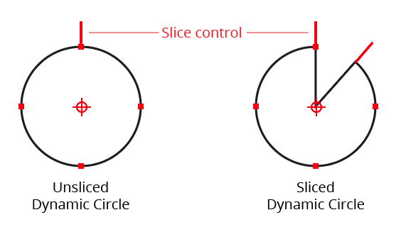
Dynamic Shapes Slices Examples
Doubleclicking
Doubleclicking either slice control resets both the start slice and end slice to zero, removing the slice.
Dragging
Dragging a slice control changes the slice value. While dragging, several keys can be pressed to modify functionality:
Shift: Constrains the slice angle to 45° increments around the general constrain angle.
Option/Alt: Links or unlinks the slice angles. When linked, moving the end slice control will simultaneously move the start slice control by the same amount. The initial state of slice linking is set in the panel.
Command/Ctrl: Changes the slice control into a rotation control (see Rotation Control Edits below).
D: Toggles Duplicate Shape mode. When enabled, when the edit is completed by releasing the mouse button, a new shape will be created with the new parameters; the original shape is untouched.
Rotation Control Edits
The rotation control resembles the slicing control, but has a small circle on the end, like a lollipop. Since advanced shape types do not support slicing, they always display this control. For standard shapes, holding down Command/Ctrl when mousing down over a slicing control converts it temporarily into a rotation control:
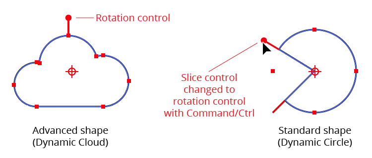
Dynamic Shapes Rotation Control Edits
Shape rotation is around the shape’s transformation point. When dragging the rotation control to rotate the shape(s), you can add Shift to constrain the rotation to 45° increments around the general constrain angle, and D to toggle Duplicate Shape mode, as previously described.
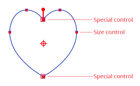
Special Control Edits
Most of the advanced shapes have special annotated controls which let you adjust one or more of their non-standard parameters without using the Dynamic Shapes panel:
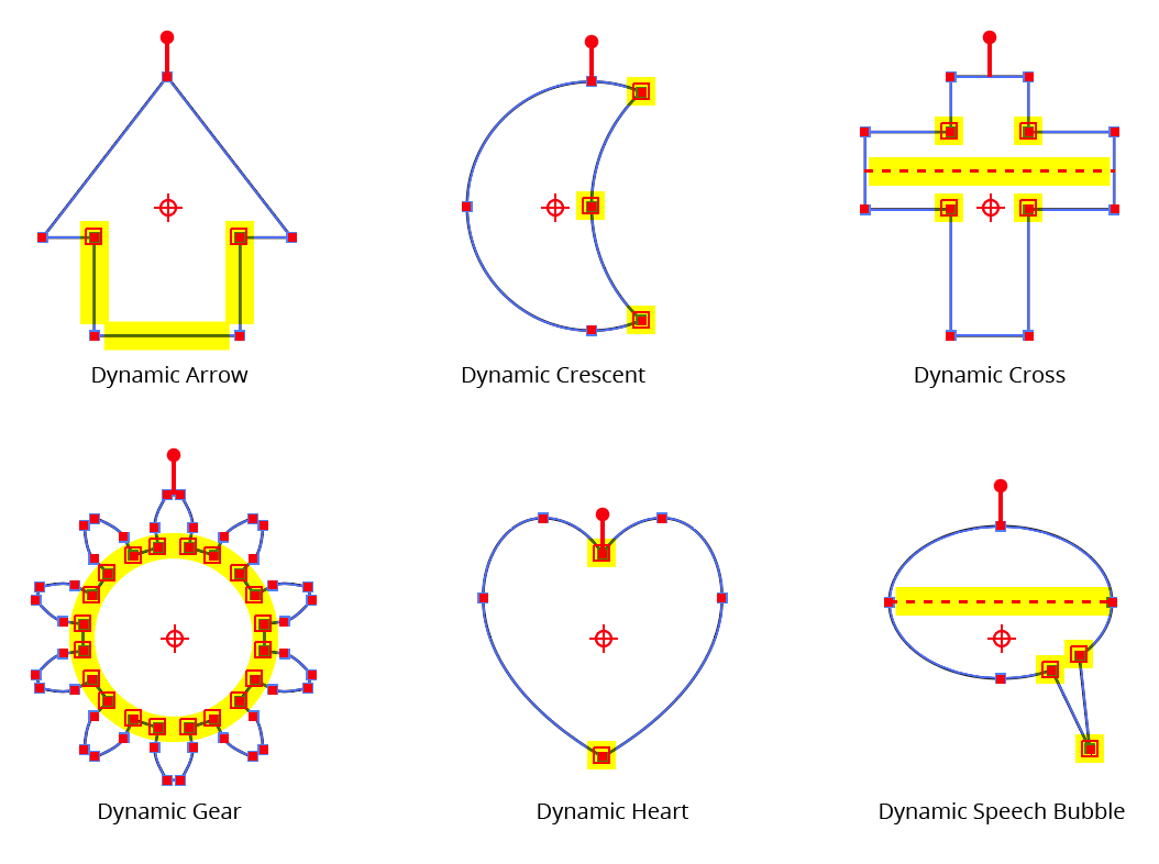
Dynamic Shapes Special Control Edits
Dynamic Arrow: The special controls on a Dynamic Arrow let you change its Tip Angle. Additionally, you can drag the sides of the arrow to adjust its Thickness, and the base of the arrow to adjust its height without affecting its width.
Dynamic Crescent: The special controls on a Dynamic Crescent let you change its Outer and Inner widths.
Dynamic Cross: The special controls on a Dynamic Cross let you change its Thickness and Offset.
Dynamic Gear: The special controls on a Dynamic Gear let you change its Tooth Height.
Dynamic Heart: The special controls on a Dynamic Heart let you change its Depth and Point.
Dynamic Speech Bubble: The special controls on a Dynamic Speech Bubble let you change its Tail Height, Tip, and Join positions. To move one Join position independently of the other, hold down
Option/Altwhen dragging it.
Illustrator Location:
Make Shape is an Astute Graphics live effect that creates paths which are basic geometric shapes from the artwork to which it is applied. In its basic form it is similar to the native “Convert to Shape” effect, but it includes many more parameters and options, such as the ability to place the shapes above or under the original artwork, the ability to change the alignment, and angle of the shape, and the ability to place multiple copies of shapes along paths. Randomization options are also included.
As with most live effects, Make Shape appears in the main menu, under Effect > AG Utilities. It can also be applied directly from the Appearance panel using the “Add New Effect” button at the bottom of the panel.
Make Shape Parameters Dialog
After applying the live effect using the menu item (or when clicking on the existing effect in the Appearance panel to edit it), the parameters dialog will appear:
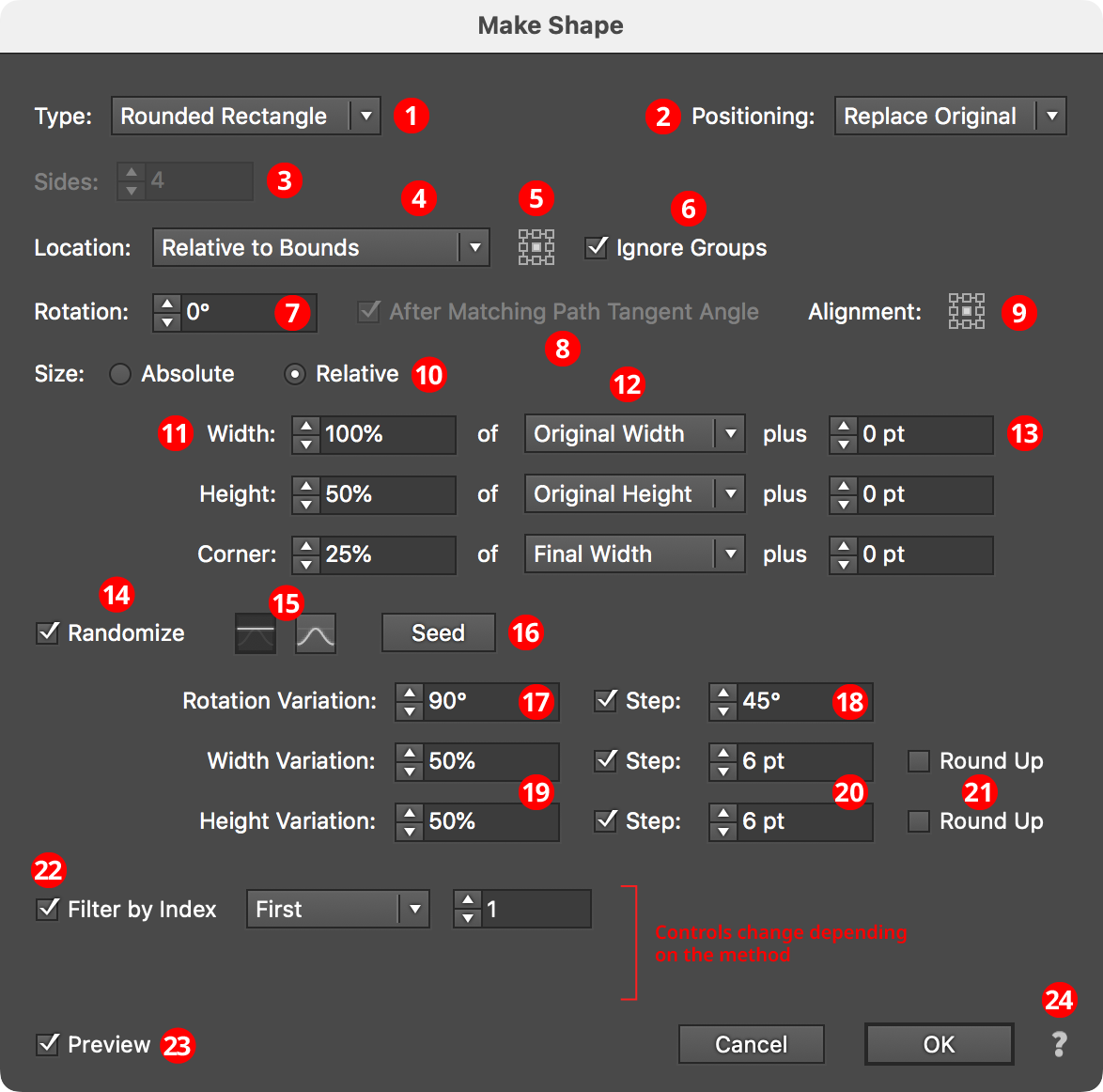
Make Shape Parameters Dialog
1. Shape Type
The type of shape to create, from among: Arc, Circle, Ellipse, Half-Circle, Line, Polygon, Rectangle, Rounded Rectangle, Square, Star, and Triangle. Depending on the type of shape selected, other parameter controls in the dialog may be hidden or changed.
2. Positioning
The position of the shape relative to the original artwork. It can replace the original (the default), or go above or below it.
3. Sides
Some of the shape types (Arc, Circle, Ellipse, Half-Circle, Polygon, and Star) allow the number of sides (anchor points for rounded shapes; points for stars) to be specified, from 3 to 1000. For Stars, an additional control will appear that lets you force the star to be “Regular” (this locks the ratio of its inner diameter to its outer diameter).
4. Location
Where to place the shape(s). The default, similar to the native “Convert to Shape” effect, is relative to the bounding box of the original artwork (note that Make Shape uses the outlines of live text to directly determine its bounding box). Other options (each will add parameter-specific controls alongside the popup menu) include:
Along Path (Once)

AG Utilities Live Effects - Make Shape Along Path Once
The shape is placed once along each path at the specified path length fraction (0 to 100%), where 0% indicates the start of the path and 100% indicates the end of the path; for closed paths, 0% and 100% refer to the same spot.
Along Path (By Count)

AG Utilities Live Effects - Make Shape Along Path by Count
The shape is placed the specified number of times along each path, equally spaced. For open paths, a shape is placed at each end except when Center is enabled: then the endpoints do not receive shapes and instead the shapes are placed along the interior of the path such that equal spacing would be maintained if multiple copies of the path were placed end-to-end. For closed paths, Center shifts the shapes such that they appear centered between the spots where they would be placed if Center were not enabled.
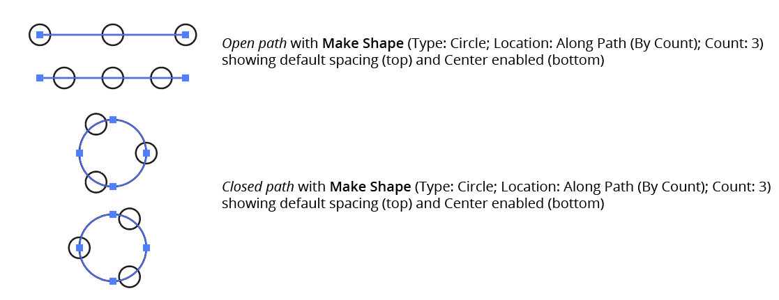
AG Utilities Live Effects - Make Shape Along Path by Count Center
Along Path (By Distance)

AG Utilities Live Effects - Make Shape Along Path by Distance
Shapes are placed along each path, starting at the first anchor point, with the specified distance between shapes. When Adjust is enabled, the spacing is modified in one of two different ways. In Center mode, the shapes are moved to be centered within the path. In Fit mode, the distance value is changed to the closest value which produces an integral number of shapes along the path.
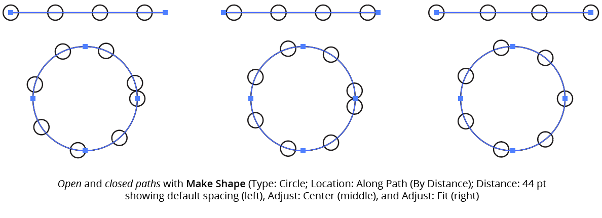
AG Utilities Live Effects - Make Shape Along Path by Distance Example
If the distance exceeds the path length, then no shapes are created unless Adjust is enabled.
Along Each Segment

AG Utilities Live Effects - Make Shape Along Each Segment
Shapes are placed along segments of each path at the specified length fraction (0 to 100%), where 0% indicates the start of the segment and 100% indicates the end of the segment. By default, all segments are included, but this can be changed to First, Last, Even Only, Odd Only, Curved Only, or Straight Only to affect only a subset of the segments.
At Anchor Points

AG Utilities Live Effects - Make Shape at Anchor Points
Shapes are placed at the positions of the anchor points of each path. By default, all anchor points are included, but this can be changed to First, Last, Even Only, Odd Only, Corner Only, or Smooth Only to affect only a subset of the anchor points.
5. Nine-block Control
When using a Location of Relative to Bounds, allows the picking of one of the nine standard positions (upper-left, upper-center, etc.) to which the shape can be oriented relative to the bounding box.
6. Ignore Groups
When using a Location of Relative to Bounds, when enabled, bounds are calculated separately for each member of any group in the original art (including groups created internally by the live effect mechanism), thereby resulting in multiple shapes if the group has more than one object (such as live text).
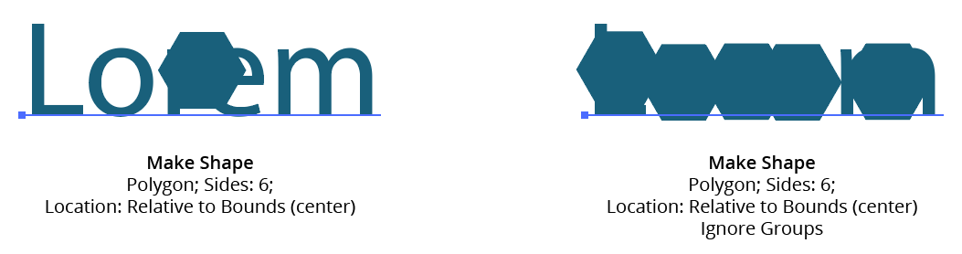
AG Utilities Live Effects - Make Shape Ignore Groups
7. Rotation
Specifies the rotation of the shape. This rotation value may be in addition to path tangent-matching rotation (see below).
8. After Matching Path Tangent Angle
This option is available when the location is set to anything other than Relative to Bounds. When enabled, the shape is first rotated to match the tangent angle at its spot along the path, and then any additional rotation specified by the rotation option is added to that value. Angles at corner points are determined by averaging the angles on either side of the point.
9. Alignment
Specifies the alignment of the shape to its nominal center point. This alignment is calculated with the shape in an unrotated state and any rotation is then carried out around the alignment point.
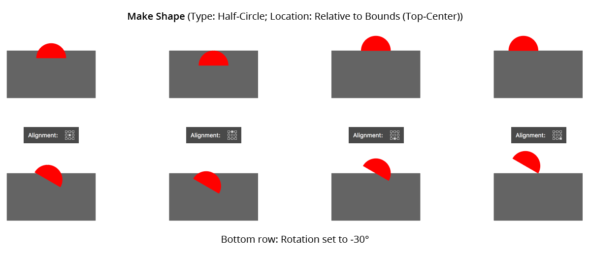
AG Utilities Live Effects - Make Shape Alignment
10. Size
When set to Absolute, the dimensions of the shape are set directly. When Relative, each dimension is based on another dimension, specified using the menu.
11. Dimensional Values
Sets the dimension(s) of the shape (shape types of Arc, Circle, Half-Circle, Line, Polygon, and Square have only a single dimension; Rounded Rectangle has three dimensions).
12. Dimensional Relative
For size Relative, specifies what the dimension is based on. For example, a circle’s diameter can be set to 50% of the original width of the art. For shape types with two or more dimensions, one dimension can be based on the other to determine its aspect ratio (for example, an ellipse’s width can be set to 200% of its height).
13. Plus Value
For size mode Relative, specifies an additional value that is added to the relatively-derived dimension, essentially giving it a minimum value.
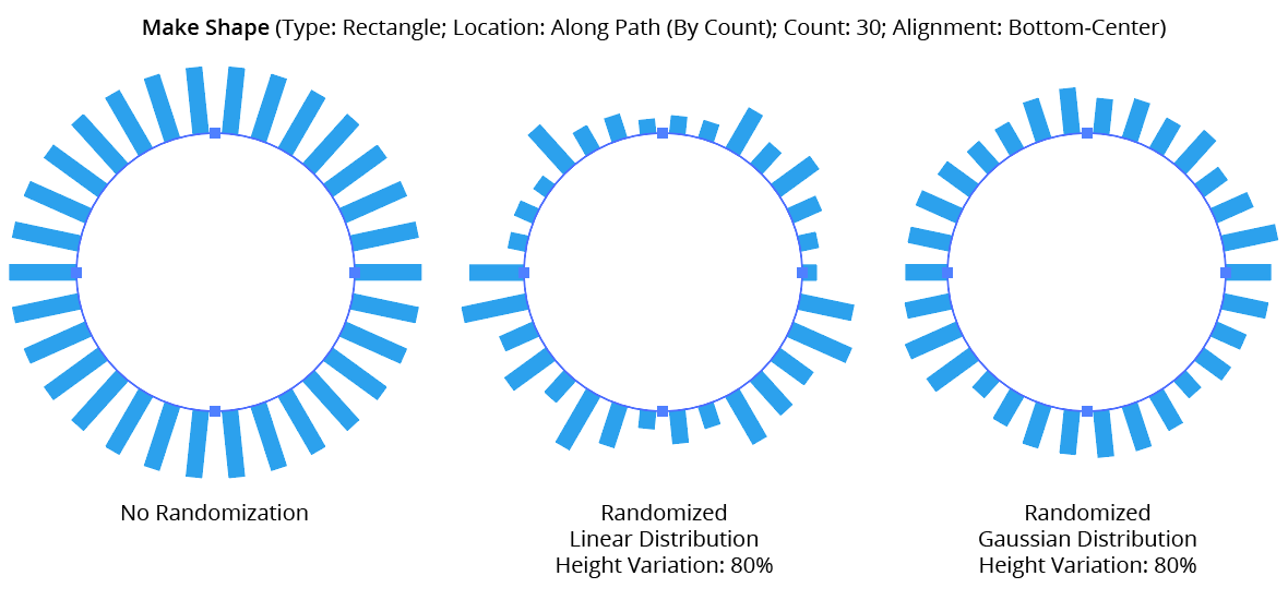
14. Randomize
Allows randomization of the rotation and dimensions of the shapes.
15. Distribution Curves
Specifies either a linear distribution in random values (all values in the range are equally likely to be chosen) or a Gaussian distribution (central values in the range are more likely to be chosen).
16. Seed
Each random seed number leads to a different sequence of random values. Clicking the button picks a new seed, thereby changing the look of the artwork. To view or specify the seed number directly, Option/Alt-click the button. This lets you recreate a previously-generated look.
17. Rotation Variation
Specifies the maximum amount of variation in the final rotation of the shapes (in either clockwise or counter-clockwise directions), in degrees. For example, if the rotation value is set to 90° and the variation is set to 15°, possible values would be between 75 and 105°.
18. Rotation Step
Constrains each final rotation value (after randomization) to multiples of the specified step value while still remaining in the original range. In the example above, where possible values range continuously between 75 and 105°, setting the step value to 10° would instead only result in values of 80°, 90° or 100°.
19. Dimensional Variations
Specifies the random variation in the first dimension of the shape. For example, using a Line shape, if the length is set to 20 pt, then a variation value of 25% would produce lengths that vary by as much as 20 pt × 25% = 5 pt, that is, between 15 pt and 20 pt; a variation value of 90% would produce lengths between 2 pt and 20 pt.
20. Dimensional Steps
Constrains each final shape dimension (after randomization) to multiples of the specified step value while still remaining in the original range. For example, using a Line shape, if the length is set to 24 pt with a random variation of 50%, then normally values of 12 to 24 pt would be produced. But enabling Step with a value of 5 pt would result in only values of 15 pt and 20 pt.
AG Utilities Live Effects - Make Shape Randomization
21. Round Up
When constraining a dimensional value to steps, enabling this setting ensures that the stepped (quantized) value is always higher then the non-quantized value. For example, suppose Make Shape were used to place a rectangle behind live text, but the rectangle needed to be a multiple of 20 pt wide. Without Round Up, the rectangle would sometimes become narrower than the text:
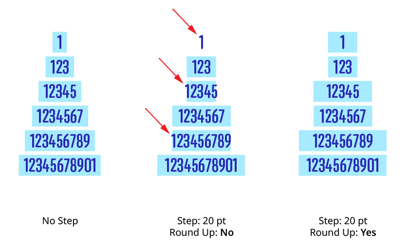
Make Shape Step Round Up
22. Filter By Index
When enabled (and the effect has been applied to a group or is inside a live effect stack which has internally created multiple objects), each art object’s index is used to determine whether it should have a shape made from it, using one of seven different methods. The index is simply an integer sequentially assigned to each object in the order it is encountered, starting with zero for the first object. Generally, the index increases going downwards in the stacking order; however, other live effects present in the appearance stack may change this order, sometimes randomly (such as PathFinder effects). Additionally, objects may be created which are invisible in the final appearance if they have no fill or stroke. The available By Index methods are as follows:
a. First: Only the first n objects are affected, where n is the specified value.

Make Shape Filter By Index - First Controls
b. Last: Only the last n objects are affected, where n is the specified value.

Make Shape Filter By Index - Last Controls
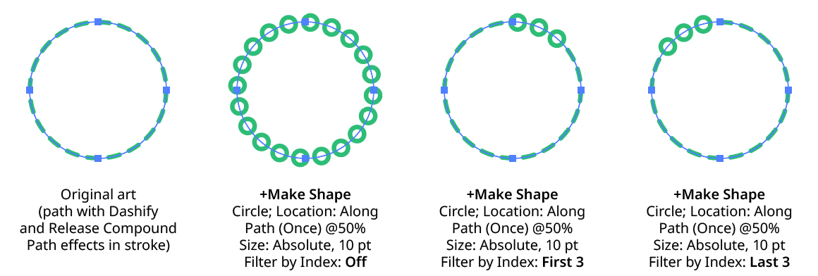
Make Shape Filter By Index - First, Last
c. First or Last: Only the first and last objects are affected.
d. Odd: Only objects with an odd index (1, 3, 5, 7...) are affected.
e. Even: Only objects with an even index (0, 2, 4, 6...) are affected.
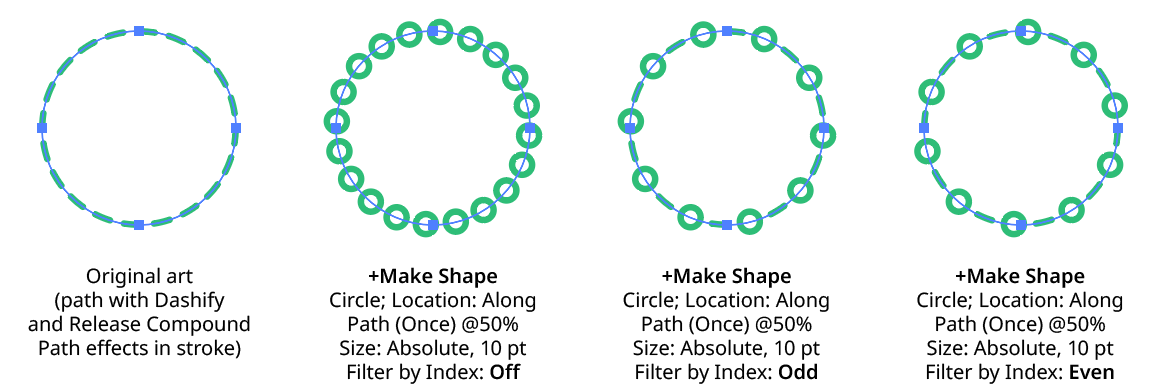
Make Shape Filter By Index - Odd, Even
f. Pattern: Creates a repeating pattern of matching indices based on the three pattern parameters.
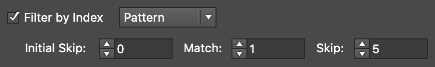
Make Shape Filter By Index - Pattern Controls
Initial Skip specifies the number of indices to skip over at the start (art with these indices will not be affected). Then, Match specified the number of indices that will match and therefore be affected. Finally, Skip specifies the number of indices to skip over following the matching indices. When the total of the values in the three parameters is less than the number of eligible art objects, the pattern repeats, using the Match and Skip values in alternation.
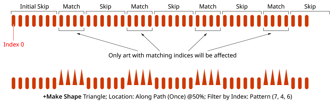
Make Shape Filter By Index - Pattern
g. Randomly: Each art object has the specified random chance (from 0% to 100%) of being affected. The parameter has an independent seed value. Just as with move/rotate/scale seed values, clicking the button picks a new seed, thereby changing the look of the artwork. To view or specify the seed number directly,
Option/Alt-clickthe button. This lets you recreate a previously-generated look.

Make Shape Filter By Index - Randomly Controls
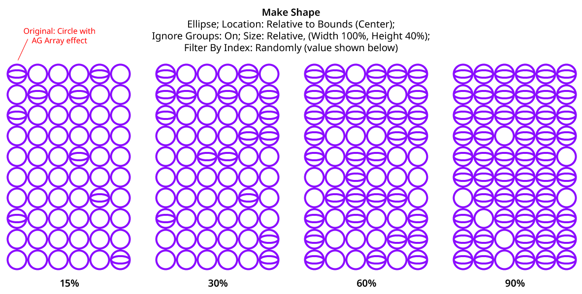
Make Shape Filter By Index - Randomly
23. Preview
As with all live effects, when enabled, changing a parameter will immediately update the artwork while the dialog is still open.
24. Help Button
pens the help documentation in the Astute Manager. If this does not automatically appear, please ensure your Astute Manager is running first.