 Make Shape Live Effect
Make Shape is an Astute Graphics live effect that creates paths which are basic geometric shapes from the artwork to which it is applied. In its basic form it is similar to the native “Convert to Shape” effect, but it includes many more parameters and options, such as the ability to place the shapes above or under the original artwork, the ability to change the alignment, and angle of the shape, and the ability to place multiple copies of shapes along paths. Randomization options are also included.
As with most live effects, Make Shape appears in the main menu, under Effect > AG Utilities. It can also be applied directly from the Appearance panel using the “Add New Effect” button at the bottom of the panel.
Make Shape Parameters Dialog
After applying the live effect using the menu item (or when clicking on the existing effect in the Appearance panel to edit it), the parameters dialog will appear:
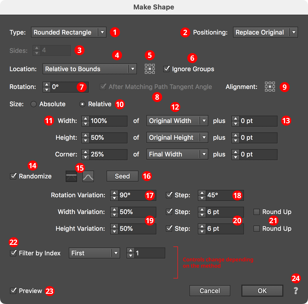
Make Shape Parameters Dialog
1. Shape Type
The type of shape to create, from among: Arc, Circle, Ellipse, Half-Circle, Line, Polygon, Rectangle, Rounded Rectangle, Square, Star, and Triangle. Depending on the type of shape selected, other parameter controls in the dialog may be hidden or changed.
2. Positioning
The position of the shape relative to the original artwork. It can replace the original (the default), or go above or below it.
3. Sides
Some of the shape types (Arc, Circle, Ellipse, Half-Circle, Polygon, and Star) allow the number of sides (anchor points for rounded shapes; points for stars) to be specified, from 3 to 1000. For Stars, an additional control will appear that lets you force the star to be “Regular” (this locks the ratio of its inner diameter to its outer diameter).
4. Location
Where to place the shape(s). The default, similar to the native “Convert to Shape” effect, is relative to the bounding box of the original artwork (note that Make Shape uses the outlines of live text to directly determine its bounding box). Other options (each will add parameter-specific controls alongside the popup menu) include:
Along Path (Once)

AG Utilities Live Effects - Make Shape Along Path Once
The shape is placed once along each path at the specified path length fraction (0 to 100%), where 0% indicates the start of the path and 100% indicates the end of the path; for closed paths, 0% and 100% refer to the same spot.
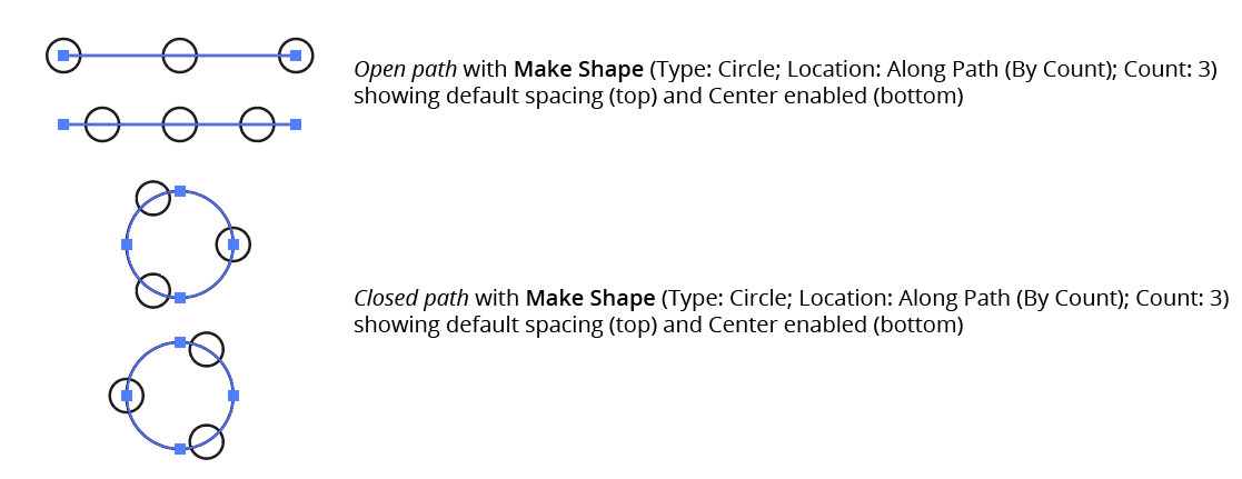
Along Path (By Count)

AG Utilities Live Effects - Make Shape Along Path by Count
The shape is placed the specified number of times along each path, equally spaced. For open paths, a shape is placed at each end except when Center is enabled: then the endpoints do not receive shapes and instead the shapes are placed along the interior of the path such that equal spacing would be maintained if multiple copies of the path were placed end-to-end. For closed paths, Center shifts the shapes such that they appear centered between the spots where they would be placed if Center were not enabled.
AG Utilities Live Effects - Make Shape Along Path by Count Center
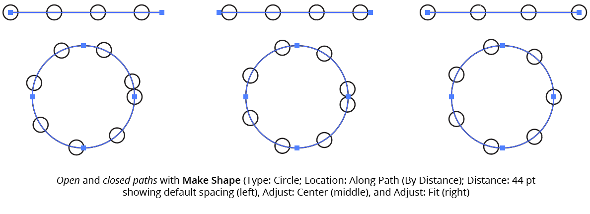
Along Path (By Distance)

AG Utilities Live Effects - Make Shape Along Path by Distance
Shapes are placed along each path, starting at the first anchor point, with the specified distance between shapes. When Adjust is enabled, the spacing is modified in one of two different ways. In Center mode, the shapes are moved to be centered within the path. In Fit mode, the distance value is changed to the closest value which produces an integral number of shapes along the path.
AG Utilities Live Effects - Make Shape Along Path by Distance Example
If the distance exceeds the path length, then no shapes are created unless Adjust is enabled.
Along Each Segment

AG Utilities Live Effects - Make Shape Along Each Segment
Shapes are placed along segments of each path at the specified length fraction (0 to 100%), where 0% indicates the start of the segment and 100% indicates the end of the segment. By default, all segments are included, but this can be changed to First, Last, Even Only, Odd Only, Curved Only, or Straight Only to affect only a subset of the segments.
At Anchor Points

AG Utilities Live Effects - Make Shape at Anchor Points
Shapes are placed at the positions of the anchor points of each path. By default, all anchor points are included, but this can be changed to First, Last, Even Only, Odd Only, Corner Only, or Smooth Only to affect only a subset of the anchor points.
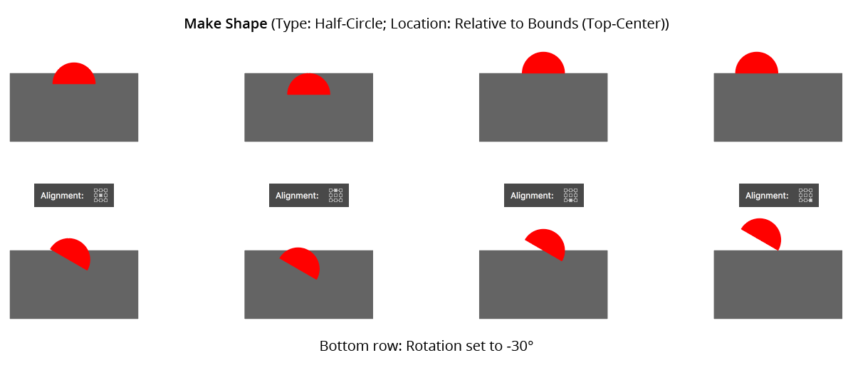
5. Nine-block Control
When using a Location of Relative to Bounds, allows the picking of one of the nine standard positions (upper-left, upper-center, etc.) to which the shape can be oriented relative to the bounding box.
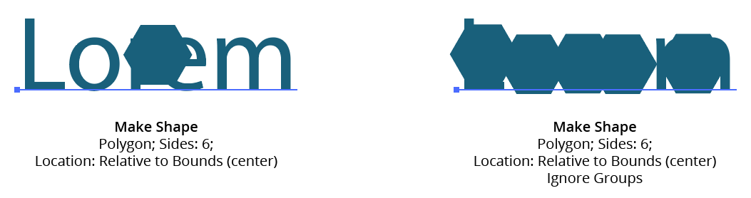
6. Ignore Groups
When using a Location of Relative to Bounds, when enabled, bounds are calculated separately for each member of any group in the original art (including groups created internally by the live effect mechanism), thereby resulting in multiple shapes if the group has more than one object (such as live text).
AG Utilities Live Effects - Make Shape Ignore Groups
7. Rotation
Specifies the rotation of the shape. This rotation value may be in addition to path tangent-matching rotation (see below).
8. After Matching Path Tangent Angle
This option is available when the location is set to anything other than Relative to Bounds. When enabled, the shape is first rotated to match the tangent angle at its spot along the path, and then any additional rotation specified by the rotation option is added to that value. Angles at corner points are determined by averaging the angles on either side of the point.
9. Alignment
Specifies the alignment of the shape to its nominal center point. This alignment is calculated with the shape in an unrotated state and any rotation is then carried out around the alignment point.
AG Utilities Live Effects - Make Shape Alignment
10. Size
When set to Absolute, the dimensions of the shape are set directly. When Relative, each dimension is based on another dimension, specified using the menu.
11. Dimensional Values
Sets the dimension(s) of the shape (shape types of Arc, Circle, Half-Circle, Line, Polygon, and Square have only a single dimension; Rounded Rectangle has three dimensions).
12. Dimensional Relative
For size Relative, specifies what the dimension is based on. For example, a circle’s diameter can be set to 50% of the original width of the art. For shape types with two or more dimensions, one dimension can be based on the other to determine its aspect ratio (for example, an ellipse’s width can be set to 200% of its height).
13. Plus Value
For size mode Relative, specifies an additional value that is added to the relatively-derived dimension, essentially giving it a minimum value.
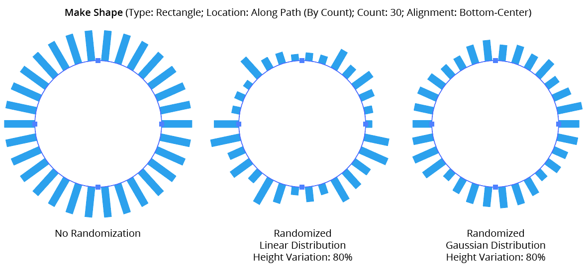
14. Randomize
Allows randomization of the rotation and dimensions of the shapes.
15. Distribution Curves
Specifies either a linear distribution in random values (all values in the range are equally likely to be chosen) or a Gaussian distribution (central values in the range are more likely to be chosen).
16. Seed
Each random seed number leads to a different sequence of random values. Clicking the button picks a new seed, thereby changing the look of the artwork. To view or specify the seed number directly, Option/Alt-click the button. This lets you recreate a previously-generated look.
17. Rotation Variation
Specifies the maximum amount of variation in the final rotation of the shapes (in either clockwise or counter-clockwise directions), in degrees. For example, if the rotation value is set to 90° and the variation is set to 15°, possible values would be between 75 and 105°.
18. Rotation Step
Constrains each final rotation value (after randomization) to multiples of the specified step value while still remaining in the original range. In the example above, where possible values range continuously between 75 and 105°, setting the step value to 10° would instead only result in values of 80°, 90° or 100°.
19. Dimensional Variations
Specifies the random variation in the first dimension of the shape. For example, using a Line shape, if the length is set to 20 pt, then a variation value of 25% would produce lengths that vary by as much as 20 pt × 25% = 5 pt, that is, between 15 pt and 20 pt; a variation value of 90% would produce lengths between 2 pt and 20 pt.
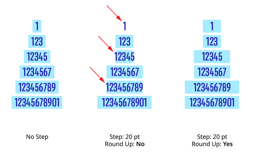
20. Dimensional Steps
Constrains each final shape dimension (after randomization) to multiples of the specified step value while still remaining in the original range. For example, using a Line shape, if the length is set to 24 pt with a random variation of 50%, then normally values of 12 to 24 pt would be produced. But enabling Step with a value of 5 pt would result in only values of 15 pt and 20 pt.
AG Utilities Live Effects - Make Shape Randomization
21. Round Up
When constraining a dimensional value to steps, enabling this setting ensures that the stepped (quantized) value is always higher then the non-quantized value. For example, suppose Make Shape were used to place a rectangle behind live text, but the rectangle needed to be a multiple of 20 pt wide. Without Round Up, the rectangle would sometimes become narrower than the text:
Make Shape Step Round Up
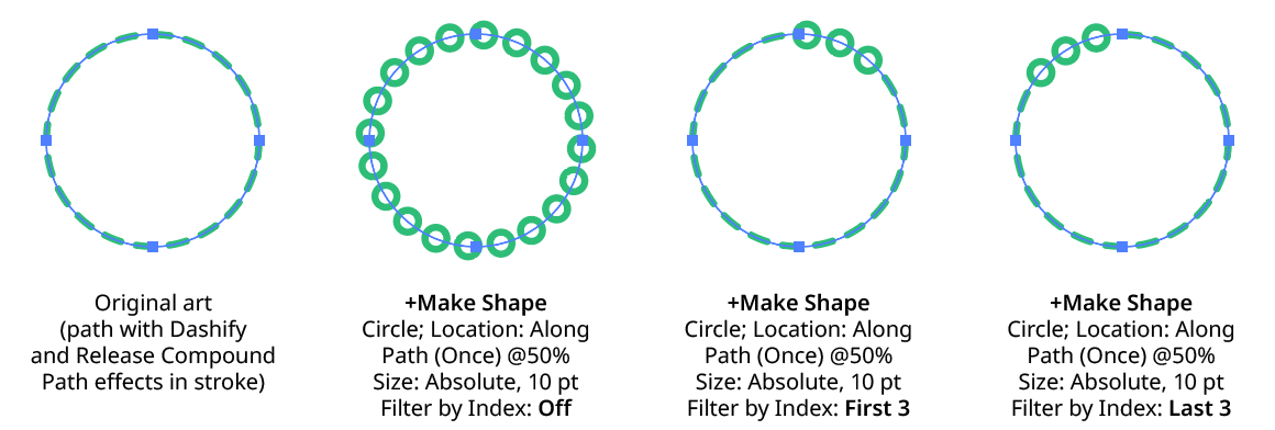
22. Filter By Index
When enabled (and the effect has been applied to a group or is inside a live effect stack which has internally created multiple objects), each art object’s index is used to determine whether it should have a shape made from it, using one of seven different methods. The index is simply an integer sequentially assigned to each object in the order it is encountered, starting with zero for the first object. Generally, the index increases going downwards in the stacking order; however, other live effects present in the appearance stack may change this order, sometimes randomly (such as PathFinder effects). Additionally, objects may be created which are invisible in the final appearance if they have no fill or stroke. The available By Index methods are as follows:
a. First: Only the first n objects are affected, where n is the specified value.

Make Shape Filter By Index - First Controls
b. Last: Only the last n objects are affected, where n is the specified value.

Make Shape Filter By Index - Last Controls
Make Shape Filter By Index - First, Last
c. First or Last: Only the first and last objects are affected.
d. Odd: Only objects with an odd index (1, 3, 5, 7...) are affected.
e. Even: Only objects with an even index (0, 2, 4, 6...) are affected.
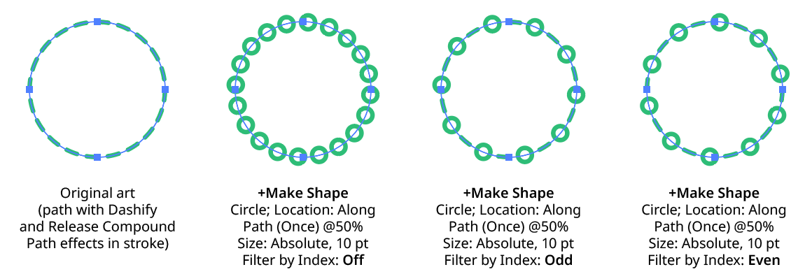
Make Shape Filter By Index - Odd, Even
f. Pattern: Creates a repeating pattern of matching indices based on the three pattern parameters.
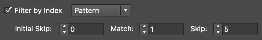
Make Shape Filter By Index - Pattern Controls
Initial Skip specifies the number of indices to skip over at the start (art with these indices will not be affected). Then, Match specified the number of indices that will match and therefore be affected. Finally, Skip specifies the number of indices to skip over following the matching indices. When the total of the values in the three parameters is less than the number of eligible art objects, the pattern repeats, using the Match and Skip values in alternation.
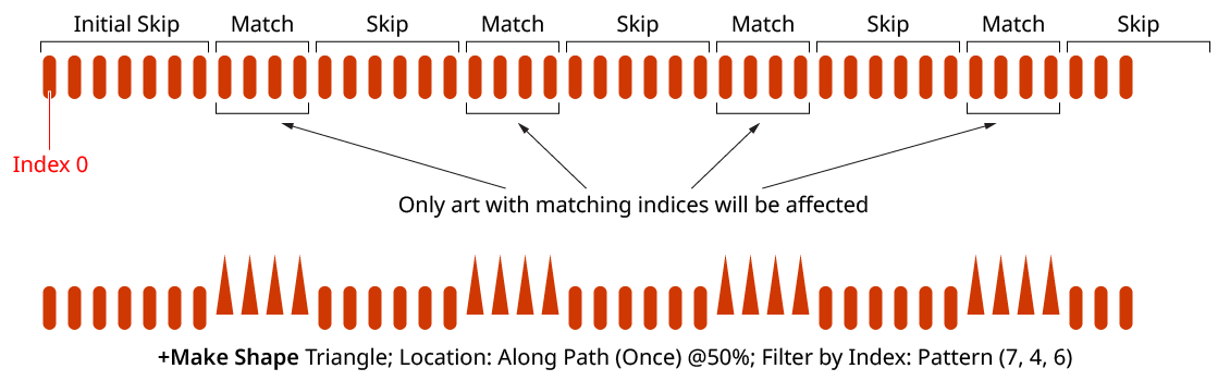
Make Shape Filter By Index - Pattern
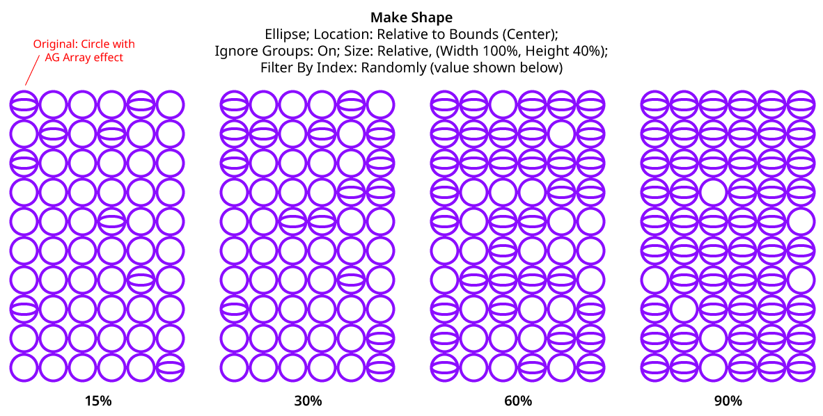
g. Randomly: Each art object has the specified random chance (from 0% to 100%) of being affected. The parameter has an independent seed value. Just as with move/rotate/scale seed values, clicking the button picks a new seed, thereby changing the look of the artwork. To view or specify the seed number directly,
Option/Alt-clickthe button. This lets you recreate a previously-generated look.

Make Shape Filter By Index - Randomly Controls
Make Shape Filter By Index - Randomly
23. Preview
As with all live effects, when enabled, changing a parameter will immediately update the artwork while the dialog is still open.
24. Help Button
pens the help documentation in the Astute Manager. If this does not automatically appear, please ensure your Astute Manager is running first.