Drawing
 Dynamic Sketch
![]() InkFlow
InkFlow
 InkScribe
![]() Dynamic Sketch Tool
Dynamic Sketch Tool
![]() InkFlow Tool
InkFlow Tool
![]() Dynamic Sketch Panel
Dynamic Sketch Panel
![]() InkFlow Panel
InkFlow Panel
Illustrator Location:
Advanced Toolbar > Shaper Stack > Dynamic Sketch Tool
Tool Location and Cursor Appearance
The Dynamic Sketch tool appears in Illustrator’s main toolbar (which must be in Advanced mode: View > Toolbars > Advanced), stacked under the native Shaper and Pencil tools. As with other stacked tools, click and hold on the top tool icon to display the tools stacked under it.
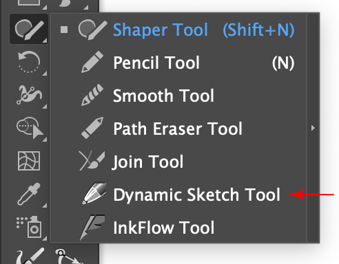
Dynamic Sketch Tool Location
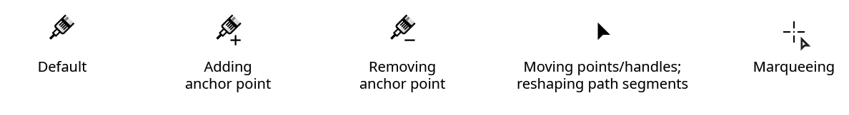
The Dynamic Sketch tool’s cursor looks like the end of a ballpoint pen, and can have additional badges depending on the mode it is operating in:
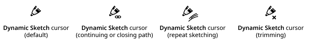
Dynamic Sketch Cursors
Illustrator Location:
Advanced Toolbar > Shaper Stack > InkFlow Tool
Tool Location and Cursor Appearance
The InkFlow tool appears in Illustrator’s main toolbar (which must be in Advanced mode: View > Toolbars > Advanced), stacked under the native Shaper and Pencil tools. As with other stacked tools, click and hold on the top tool icon to display the tools stacked under it.
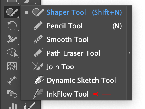
InkFlow Tool Location
The InkFlow tool’s cursor is a quill. When the mouse button is up, the shape of the pen tip is annotated underneath it with an ellipse. When closing a path, or continuing/editing an existing selected path, a “link” badge is added.

InkFlow Cursors
Illustrator Location:
Advanced Toolbar > Pen Stack > InkScribe Tool
The InkScribe tool appears in Illustrator’s main toolbar (which must be in Advanced mode: View > Toolbars > Advanced), stacked under the native Pen tool. As with other stacked tools, click and hold on the top tool icon to display the tools stacked under it.
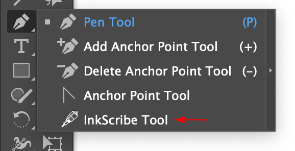
InkScribe Tool Location
The InkScribe tool’s primary cursor looks like the end of a technical pen, and can have badges and additional forms:
InkScribe Tool Cursors
Illustrator Location:
As the Dynamic Sketch tool has several keypresses which can add or change its functionality, we suggest installing the free Astute Graphics plugin Astute Buddy, which creates a panel that dynamically updates to inform you of the various keys which can be pressed in the tool’s current context.
Nearly all the functionality of the Dynamic Sketch tool is controlled by the associated Dynamic Sketch panel, which should be open and accessible.
At its most basic, the Dynamic Sketch tool is a direct replacement for the native Pencil tool: dragging the tool on the artboard creates a trail of points, referred to here as a “sketch path.” By default, the cursor is pulled by a “string” which is 50 pixels long, which creates smoother paths. When the mouse button is released, the points are converted to a path using various settings which determine how faithfully the path should conform to the original input points, whether anchor points are automatically created at horizontal and vertical tangencies, and so on. The new path’s style depends on several settings as well. By default, the path will have a stroke of variable width (ranging from 0 to 8pt), with the stroke weight determined by the speed that the cursor was moved across the artboard (faster speeds equating to a thinner weight). As the path is being drawn, the weight of the stroke will, by default, be previewed on the screen.
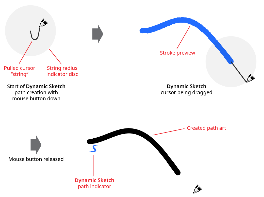
Dynamic Sketch Basic Example
Generally, Dynamic Sketch paths remain “live” after creation: their smoothness, accuracy, and stroke weight input parameters can be freely changed using the Dynamic Sketch panel controls to update the artwork. A path which is a live Dynamic Sketch path will, by default, have a small blue “S” icon annotated by the start of the path. If the path is not selected, the icon will be dimmed.
The default behavior of the tool is to allow editing, continuing, and joining paths. In each of these cases, the tool’s cursor will display a small “links” badge next to it to indicate that dragging it from the current point will not create a new path, but will instead edit, continue, or join the existing path, which can be a Dynamic Sketch path or a path created by another tool.
If the cursor is dragged from a spot along an existing path, the path will be edited to have a new shape:
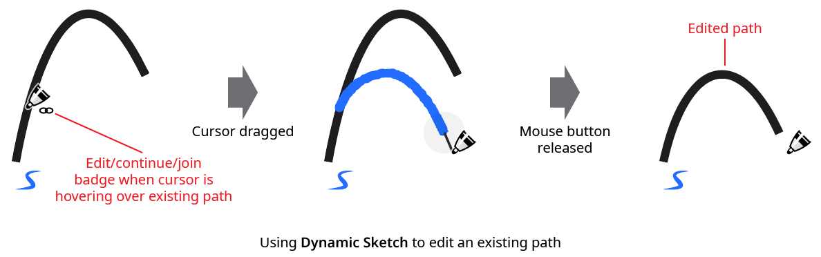
Dynamic Sketch Edit Path
If the cursor is dragged from an endpoint of an existing path, the path will be continued, with a new section added:
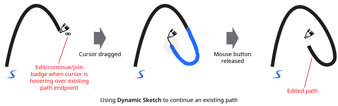
Dynamic Sketch Continue Path
Finally, if the cursor is dragged from one endpoint of an existing path to another endpoint, the path will be joined to another path (an open path can also be closed by connecting its endpoints):
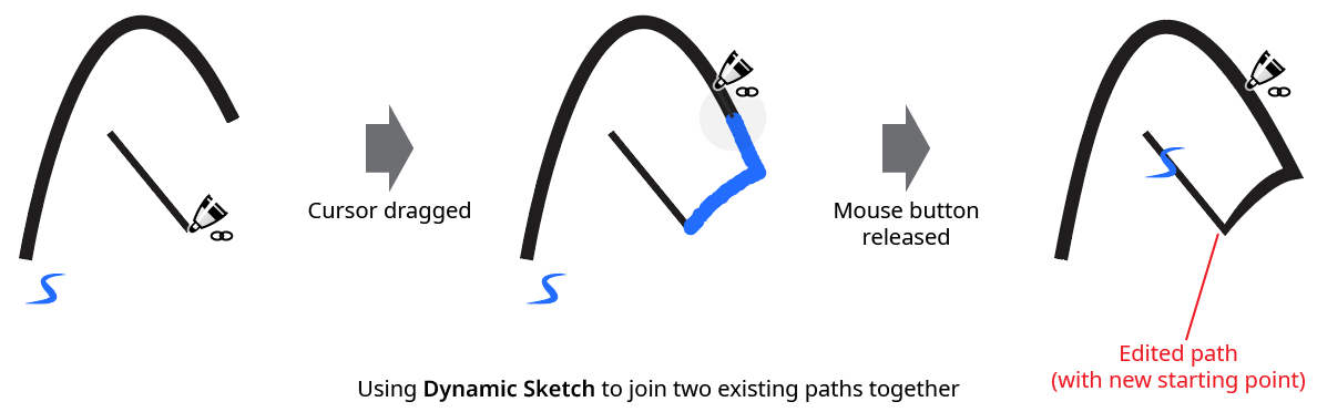
Dynamic Sketch Join Path
When joining one path to another and their stroke widths are different, the width will be blended in an attempt to join them smoothly. Tolerance values for determining how close the cursor must be to edit, continue, or join can be set in the preferences.
While dragging the tool to create a path, several keys may be pressed to held down for additional options:
Esc: Aborts the path currently being drawn.
Option/Alt: Starts a “rubberband” section – a completely straight section of path that stretches between the point at which the modifier key was held down and the point at which it is released:
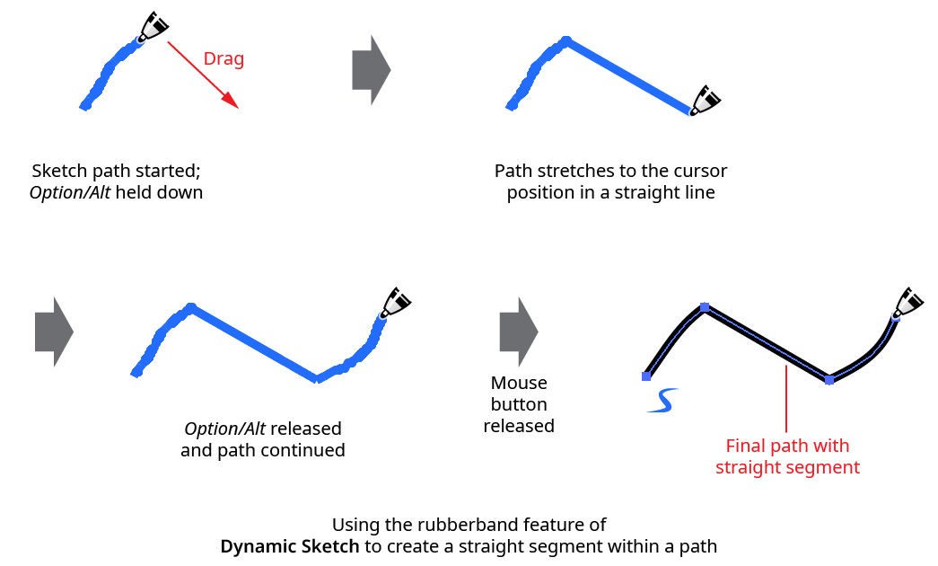
Dynamic Sketch Rubberband Example
Shift: When creating a rubberband section, constrains the rubberband to angles that are 45° increments around the general constrain angle.
Up Arrow/Down Arrow: Lengthens or shortens the pulled cursor string length.
C: Changes the annotation color among the following choices: blue (default), red, magenta, green, cyan, and black.
E: Toggles Edit/Continue/Join mode (discussed previously).
M: Toggles annotation mirroring (see Dynamic Sketch: Preferences).
S: Toggles stroke width preview (see Dynamic Sketch: Preferences).
Other features and operations of the Dynamic Sketch tool are discussed in conjunction with the Dynamic Sketch panel, below.
Illustrator Location:
The InkFlow tool works largely in conjunction with the associated InkFlow panel, which should generally be open and accessible. If you are using the free Astute Graphics plugin DirectPrefs, you can have the InkFlow panel automatically be shown when the InkFlow tool is selected.
After selecting the InkFlow tool from the toolbox (or by clicking on the blue panel banner in the InkFlow panel), simply drag it to create a calligraphic stroke, in which the ellipse representing the tip is extruded along the tool’s path. The tool’s size, roundness, and angle will reflect what is specified on the panel.
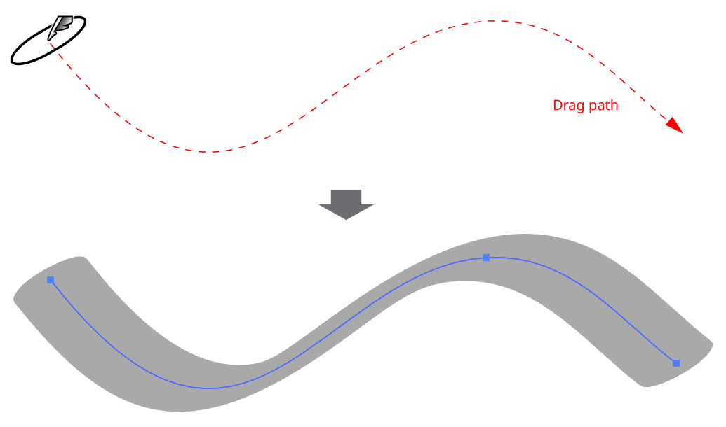
InkFlow Basic Example
The pen’s size can be adjusted (before, but not while dragging) by using the keys assigned to Decrease Diameter and Increase Diameter in the native Keyboard Shortcuts dialog (the left and right square bracket keys respectively, by default, for English language keyboards). If one or more InkFlow paths are selected, the first use of either keypress will deselect the path(s) rather than change the size. The pen size may also be changed via the InkFlow panel. When using a stylus input device, and pressure-control is enabled for the pen size, the cursor’s preview ellipse shows its maximum size.
While dragging, a preview of the stroke will be shown (in black, by default). Just as with the native Brush, this preview is only approximate and is not as smooth or refined as the final stroke.
An existing InkFlow path can be continued or reshaped by the InkFlow tool as long as the path is selected and the Edit Continue Selected Paths preference is enabled (which is the default). Additionally, the cursor must start within a certain distance (specified in the preferences dialog) of the existing path. When this is the case, the cursor will display a “link” badge, indicating that Edit/Continue mode is active. Dragging will then edit or continue the existing path, much like the native Pencil tool. Two InkFlow paths can also be joined together; the joined path will receive the appearance of the path which is lower in the stacking order.
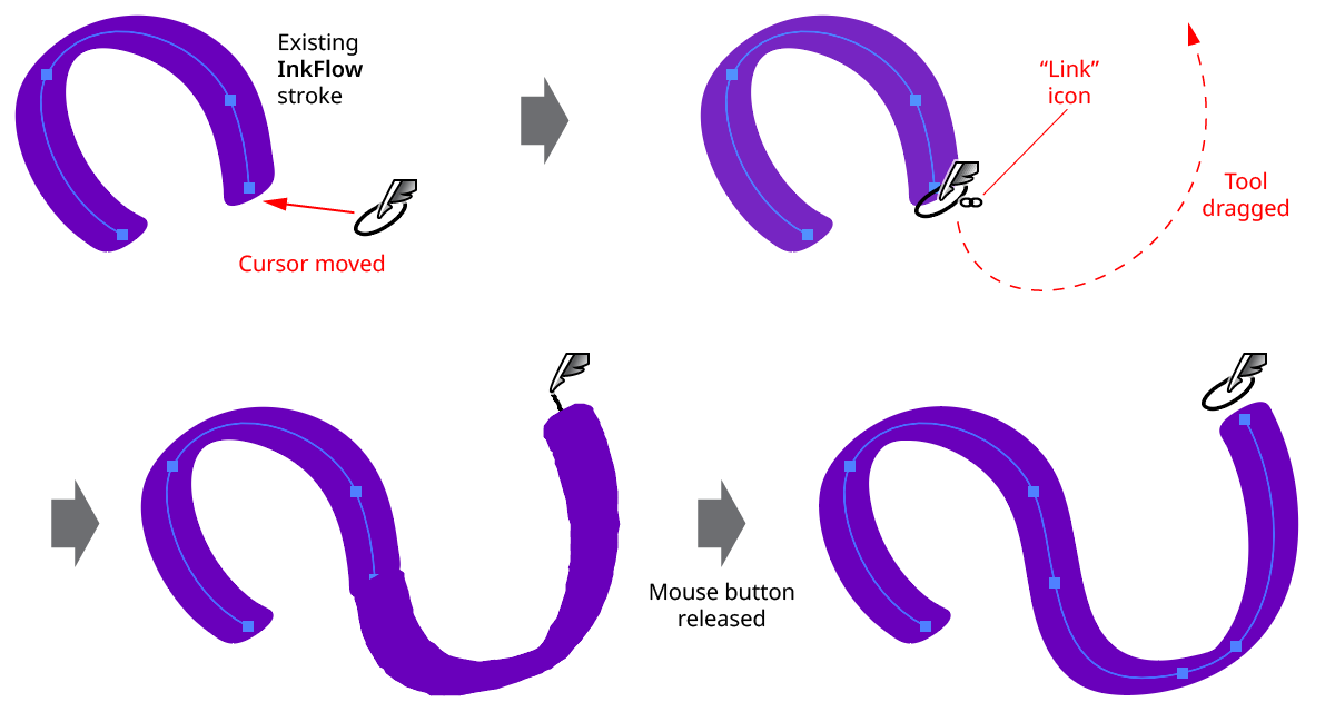
InkFlow Continue Path
Unless the InkFlow preference Expand Strokes is enabled, paths drawn with the InkFlow tool will be assigned the InkFlow live effect, which can be seen in the Appearance panel. As with all live effects, it can be hidden or shown, moved to a different path, or have its parameters changed any time after the path was drawn (using the InkFlow panel), which allows you to try different looks without having to repeatedly redraw the path from scratch.
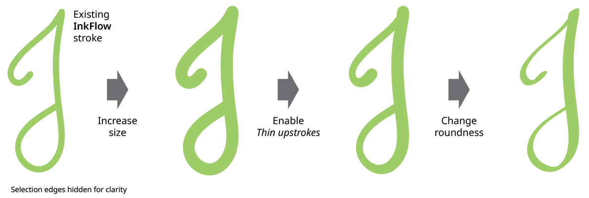
InkFlow Changing Parameters
Like the Astute Graphics Dynamic Sketch tool, the InkFlow tool cursor is pulled by a virtual “string,” which can be set from 1 to 100 pixels in length. A pulled cursor has the effect of smoothing out small jitters in its motion, resulting in a smoother path. With higher string lengths, sharp corners can be easier to create, because moving backwards slightly with the cursor simply creates slack on the string without creating new path points; the cursor can then be pulled in a new direction to create the sharp corner.
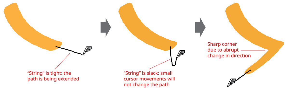
InkFlow Pulled Cursor
When an InkFlow path is drawn, it is given a stroke (unless the new art style already has one) and any fill is removed. The InkFlow live effect is added and positioned below the stroke and fill, and replaces the basic stroke. Adding a fill color generally only makes sense if the drawn path is closed.
However, if the InkFlow live effect is moved to the top of Appearance stack, then the stroke and fill are applied to the outline of the calligraphic stroke, allowing additional creative possibilities:
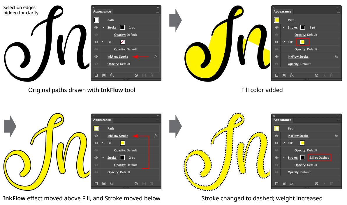
InkFlow Live Effect Positioning
Although InkFlow is a live effect, it is not possible to add it directly from the live effects menu like most live effects. Instead, at least the first instance must be generated by the InkFlow tool.
Other features and operations of the InkFlow tool are discussed in conjunction with the InkFlow panel, below.
Illustrator Location:
Illustrator Main Menu > Window > Astute Graphics > Dynamic Sketch
The menu item to show and hide the Dynamic Sketch panel can be found in the main menu under Window > Astute Graphics > Dynamic Sketch.
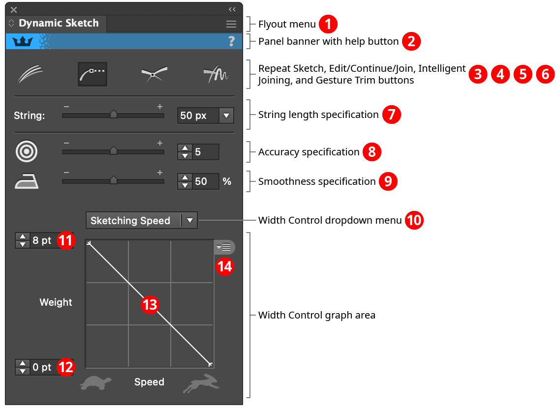
Dynamic Sketch Panel
1. Flyout menu
See Dynamic Sketch Panel: Flyout Menu.
2. Panel banner
The Dynamic Sketch panel banner has a help button on the right which opens the help documentation in the Astute Manager. If this does not automatically appear, please ensure your Astute Manager is running first. Along with the rest of the panel, the panel banner can be clicked to activate the Dynamic Sketch tool. This is a quick method of locating the tool within the default Advanced toolbar or a custom toolbar.
3. Repeat Sketch Button
Toggles Repeat Sketch mode for the Dynamic Sketch tool. When Repeat Sketch is enabled, the tool can be dragged multiple times and the final path will be an average of all the individual sketch paths (both positions as well as widths), thereby smoothing it out:
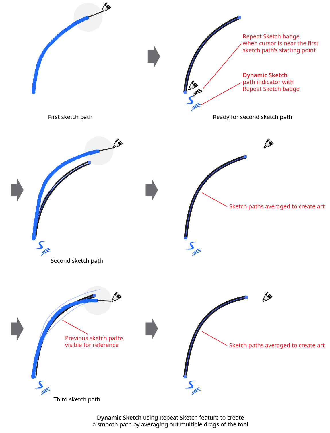
Dynamic Sketch Repeat Sketch Example
Each repeat sketch path must start within a certain distance from the original sketch path’s starting point. This distance has a default value of 50 pixels, but can be customized in the preferences dialog.
By default, if a new sketch path is drawn that does not begin near the start of a repeat sketch path, then the repeat sketch path is automatically finalized (combining all the separate sketch paths into a single one). To finalize an existing repeat sketch path without drawing a new path, use the tool and Shift+Option/ Alt-click on the path indicator, which will change to indicate the function. A finalized path (or one that was drawn when Repeat Sketching was disabled) can be turned back into a Repeat Sketch path using the same method.
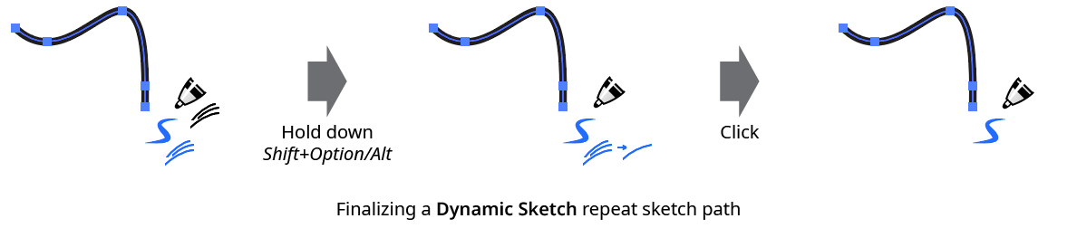
Dynamic Sketch Finalize Repeat Sketch
Repeat Sketching on a closed path will generally result in it becoming open. To average several passes and retain a closed path, see the preference Auto-Detect Continuous Repeated Closed Path Sketches.
4. Edit/Continue/Join Button
Toggles the ability to edit, continue, or join existing paths. See Dynamic Sketch: Tool for information on this mode, which is enabled by default.
5. Intelligent Joining Button
Toggles intelligent path joining mode. When this mode is enabled, sketch paths drawn so that they intersect one or at most two existing, selected paths will be automatically trimmed and joined to that path or paths. The shorter lengths of the paths on either side of the potential join point(s) are the ends of the paths which are trimmed.
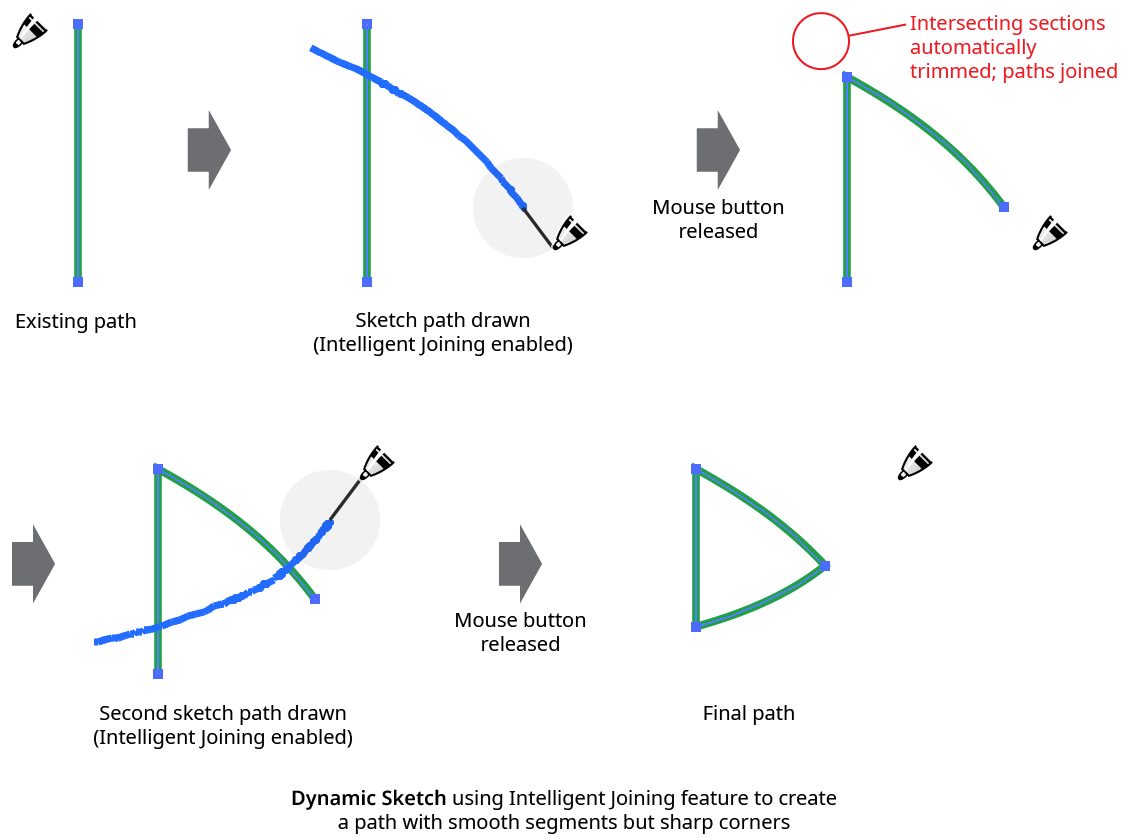
Dynamic Sketch Intelligent Joining Example
Using intelligent joining is generally the easiest method for creating shapes with smooth sides but sharp corners.
6. Gesture Trim Button
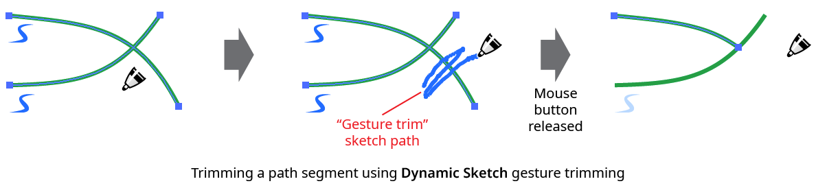
Toggles the gesture trim feature on and off. When gesture trimming is enabled, paths or sections of paths (which need not be Dynamic Sketch paths) can be deleted by “scribbling” across them – i.e., sketching a path made up of between two and five short strokes roughly perpendicular to the target path section. This is generally most natural when using a stylus and a short (or no) string.
Dynamic Sketch Gesture Trimming
An easier method of trimming a path, which does not require gesture trimming to be enabled, is to hold Shift before starting to drag and then draw a sketch path across the target path(s). When using this method, the cursor will display a small “X” badge, will not use its string (if any), and will annotate its path in a dashed line. As with normal sketch paths, the Option/Alt key may be used to create a straight trimming section.
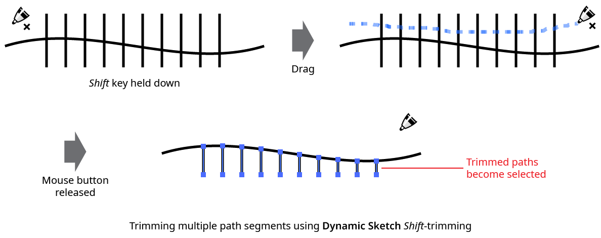
Dynamic Sketch Shift Trimming
If a path which does not cross any other paths is trimmed, the entire path will be deleted. Closed paths can only have one section deleted at a time.
When a path with variable width stroke is trimmed, Dynamic Sketch attempts to retain the width profile(s) of the untrimmed section(s) as they existed prior to the trimming.
7. String Length Specification
Specifies the length of the virtual string used to pull the cursor, from 0 pixels to 500 pixels. Longer strings generally make for smoother curves, but make it more difficult to draw small features. The default value is 50 pixels.
8. Accuracy Specification
Specifies the accuracy level (from 0 to 10) with which the final path conforms to the sketch path (the trail laid down when the tool was dragged on the artboard). Existing Dynamic Sketch paths that are selected can still have their accuracies changed using the slider or value input control. The default accuracy is 5. Depending on the sketch path, changing the accuracy from one value to another nearby value may not always produce a visible change in the path. Higher accuracies will generally require more anchor points.
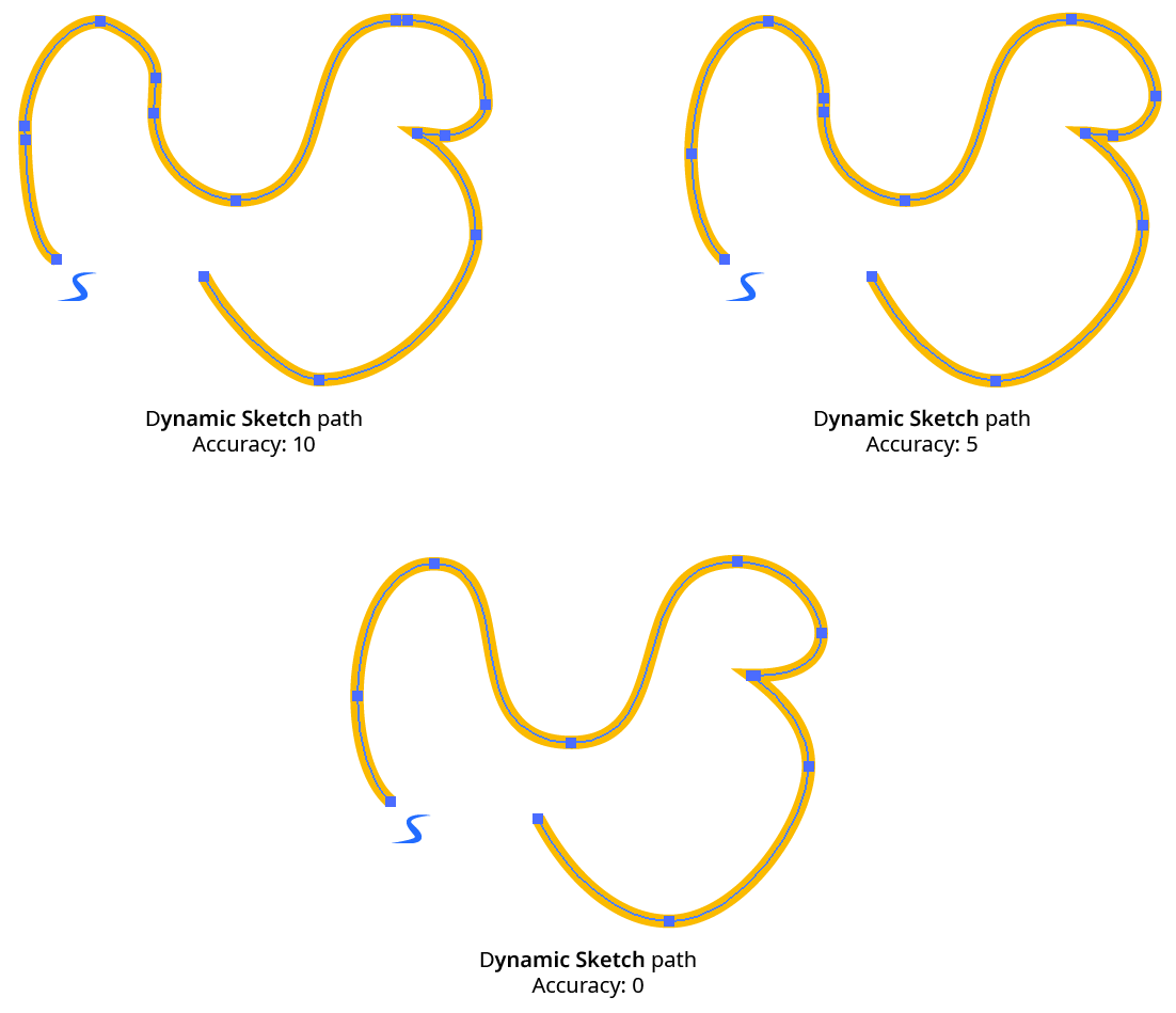
Dynamic Sketch Accuracy Examples
Clicking on the Accuracy icon will change the accuracy value to its default value. The default value to use when doing this can be set by Option/Alt-clicking on the icon.
9. Smoothness Specification
Specifies the smoothness level (from 0% to 100%) of the final path. Existing Dynamic Sketch paths that are selected can still have their smoothness values changed using the slider or value input control. The default smoothness is 50%. Smoothness only has a subtle effect on path shape, but is more important for stroke width (when using variable widths), as generally the cursor speed or stylus parameter used to control the width is difficult to vary in a completely smooth manner:
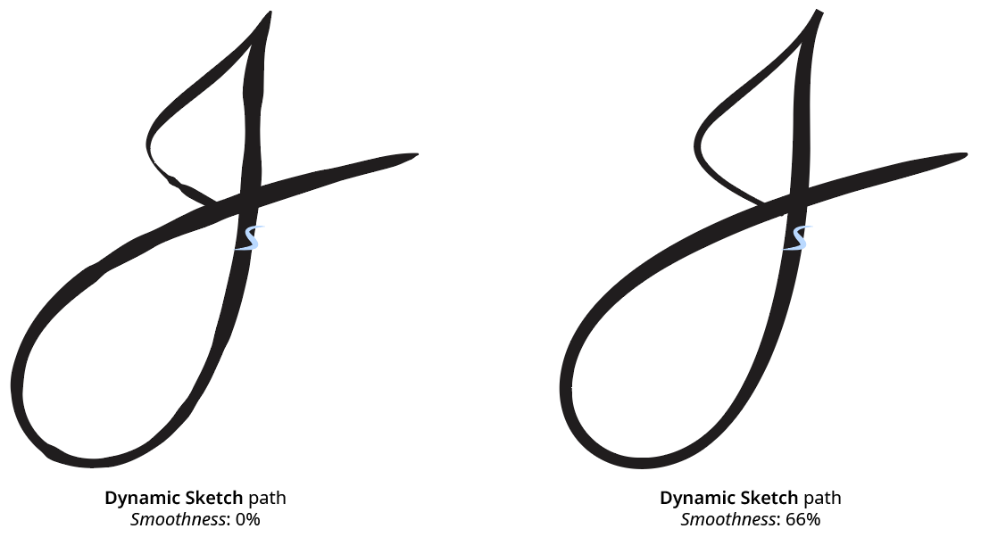
Dynamic Sketch Smoothness Example
Clicking on the Smoothness icon will change the smoothness value to its default value. The default value to use when doing this can be set by Option/Alt-clicking on the icon.
10. Width Control Dropdown Menu
This item, and all items below it, are only visible on the panel if the panel flyout menu item Show Input Graph has been enabled. The Width Control dropdown menu specifies how the stroke width of the path is determined. When the menu is set to None, the width is taken from the current appearance that is applied any new path art (unless the Dynamic Sketch preference New Paths Have Basic Appearance is enabled; in that case, the path will not include multiple strokes or fills, or live effects). When the current appearance includes a variable width stroke profile, the variable width is, by default, previewed in real time as the sketch path is being drawn (unlike the native Pencil tool).
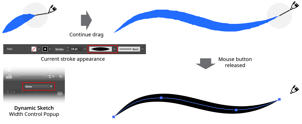
Dynamic Sketch Variable Sketch Width Profile Preview
If the Width Control dropdown menu is set to Speed (the default), the stroke width is determined by the speed with which the cursor was moved over the artboard along the length of the path, in conjunction with the graph. If set to one of the stylus parameters (Stylus Pressure, Stylus Wheel, Stylus Tilt, Stylus Bearing, or Stylus Rotation), then the stroke width is determined by the corresponding stylus parameter as it was recorded along the path, again in conjunction with the graph.
11. and 12. Maximum and Minimum Stroke Weight Values
These values specify the largest and smallest stroke weights that the variable width stroke will contain. For example, if the maximum value is set to 12 pt, the minimum value is set to 1 pt, the Width Control dropdown menu is set to Stylus Pressure, and the graph is the default linear graph, then places along the path where the stylus was being held down with maximum pressure would have a stroke weight of 12 pt, while places where the stylus had minimum pressure would have a stroke weight of 1 pt. The values can be changed after the path is drawn, if it remains selected.
13. Width Control Graph
Specifies the relationship between the maximum and minimum values and the input parameter. The horizontal axis represents the input parameter (for example, stylus pressure) from 0% to 100%, while the vertical axis represents the stroke weight, specified by the maximum and minimum value inputs. With the default diagonal line, the relationship is a linear one. Nodes on the curve may be moved simply by clicking and dragging them. A new node may be added by clicking at a spot along the curve which does not already have a node. Nodes (except the ones at the beginning and the end of the curve) may be deleted by dragging them off the graph area.
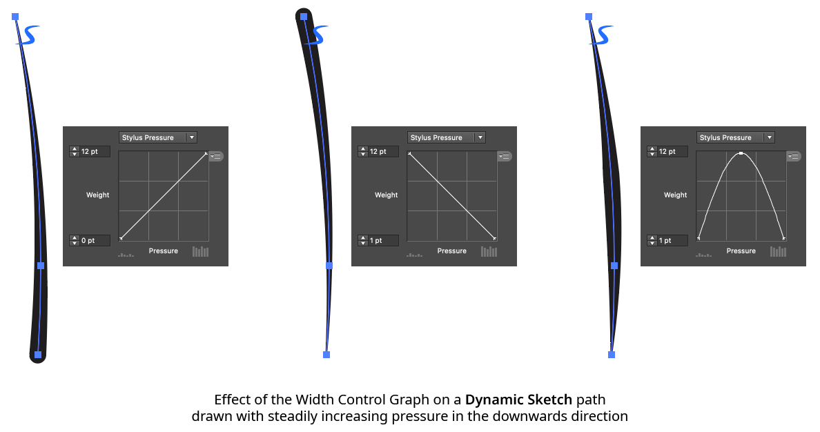
Dynamic Sketch Graph Example
14. Width Control Graph Preset Menu
Provides access to saving, managing, and applying graph settings.
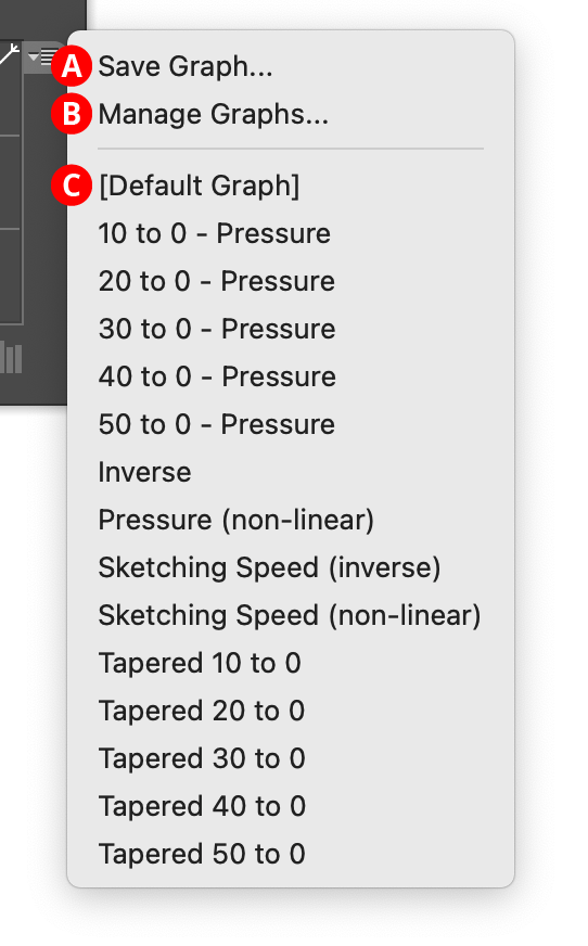
Dynamic Sketch Graph Preset Menu
A. Save Graph...
When you save the current graph, its nodes and maximum and minimum values are captured to an internal file which can be recalled later. The file name may be specified.
B. Manage Graphs...
Brings up the Manage Graphs dialog, which lets you rename, delete, import, or export graph files:
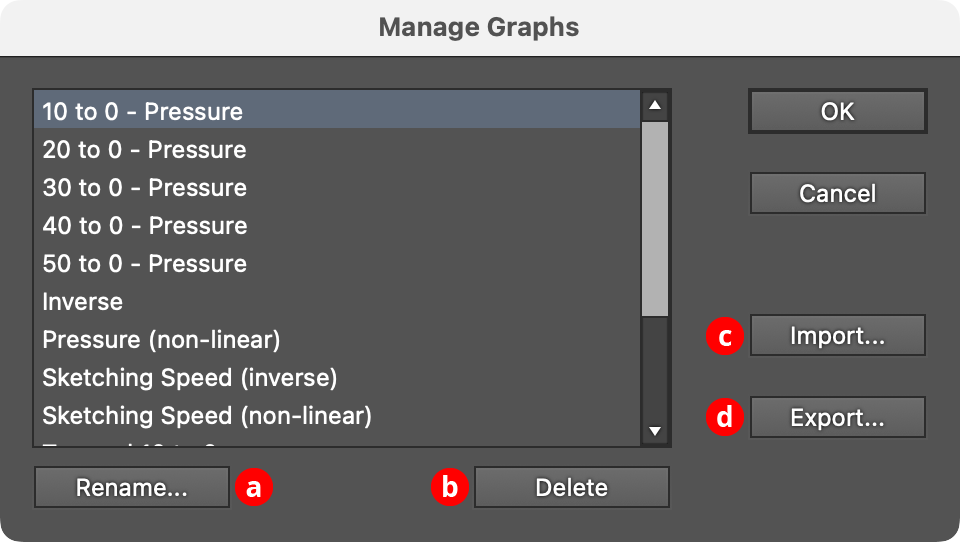
Dynamic Sketch Manage Graphs Dialog
a. Rename: Allows the selected graph file to be renamed.
b. Delete: Removes the selected graph file(s).
c. Import...: Imports a previously-exported graphs package file of type “.dsg” using the standard operating system open file dialog.
d. Export...: Exports the selected graph(s) into a graphs package file of type “.dsg” using the standard operating system save file dialog. This file could be used as a backup or passed to another user.
C. Graphs List
Choosing a graph file from this list will update the graph to the values saved within that file (or, the case of “[Default]”, to the default graph).
Illustrator Location:
Illustrator Main Menu > Window > Astute Graphics > InkFlow
The menu item to show and hide the InkFlow panel can be found in the main menu under Window > Astute Graphics > InkFlow. The panel has two modes, Basic and Expanded, which can be switched between using the panel flout menu (see InkFlow Panel: Flyout Menu). The expanded mode includes response curves that map stylus inputs to output values, for additional control. Changing a parameter on the panel (except String length) will also change it for any existing, selected InkFlow strokes.
Illustrator Location:
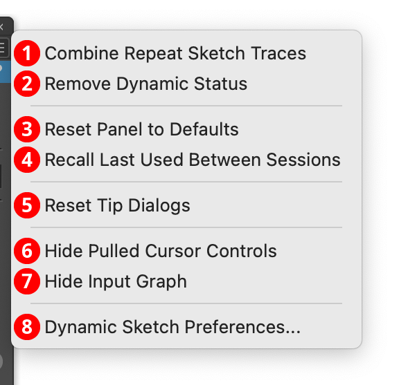
Dynamic Sketch Panel Flyout Menu
The Dynamic Sketch panel flyout menu items are contextually sensitive and all items may not be available, depending on the current selection.
1. Combine Repeat Sketch Traces...
Combines the repeat sketch traces of the selected Dynamic Sketch path, averaging them to create a single sketch path. This is the same as Shift+Option/Alt-clicking on the path indicator icon with the tool.
2. Remove Dynamic Status
Converts the selected Dynamic Sketch paths into “regular” paths. Once this is done, their accuracy, smoothness, and width input settings can no longer be changed. Most operations made to a Dynamic Sketch path outside the tool (scaling or rotating it, adding points to it, etc.) will automatically remove the dynamic status.
3. Reset Panel to Defaults
Resets all panel controls (including the width input graph) to their default settings.
4. Recall Last Used Between Sessions
When enabled, the Dynamic Sketch panel’s state will be retained between launches of Illustrator.
5. Reset Tip Dialogs
If one or more of Dynamic Sketch’s tip dialogs have been suppressed using the Don’t show again checkbox, choosing this menu item will re-enable them.
6. Hide Pulled Cursor Controls
The pulled cursor string length slider and input value can be shown or hidden on the panel using this menu item. When the controls are hidden, the menu item will change to Show Pulled Cursor Controls.
7. Hide Input Graph
The entire lower width control section of the panel can be toggled using this menu item. When hidden, the panel takes significantly less vertical space. In this state, the menu item will change to Show Input Graph.
8. Dynamic Sketch Preferences...
Brings up the Preferences dialog.
Illustrator Location:
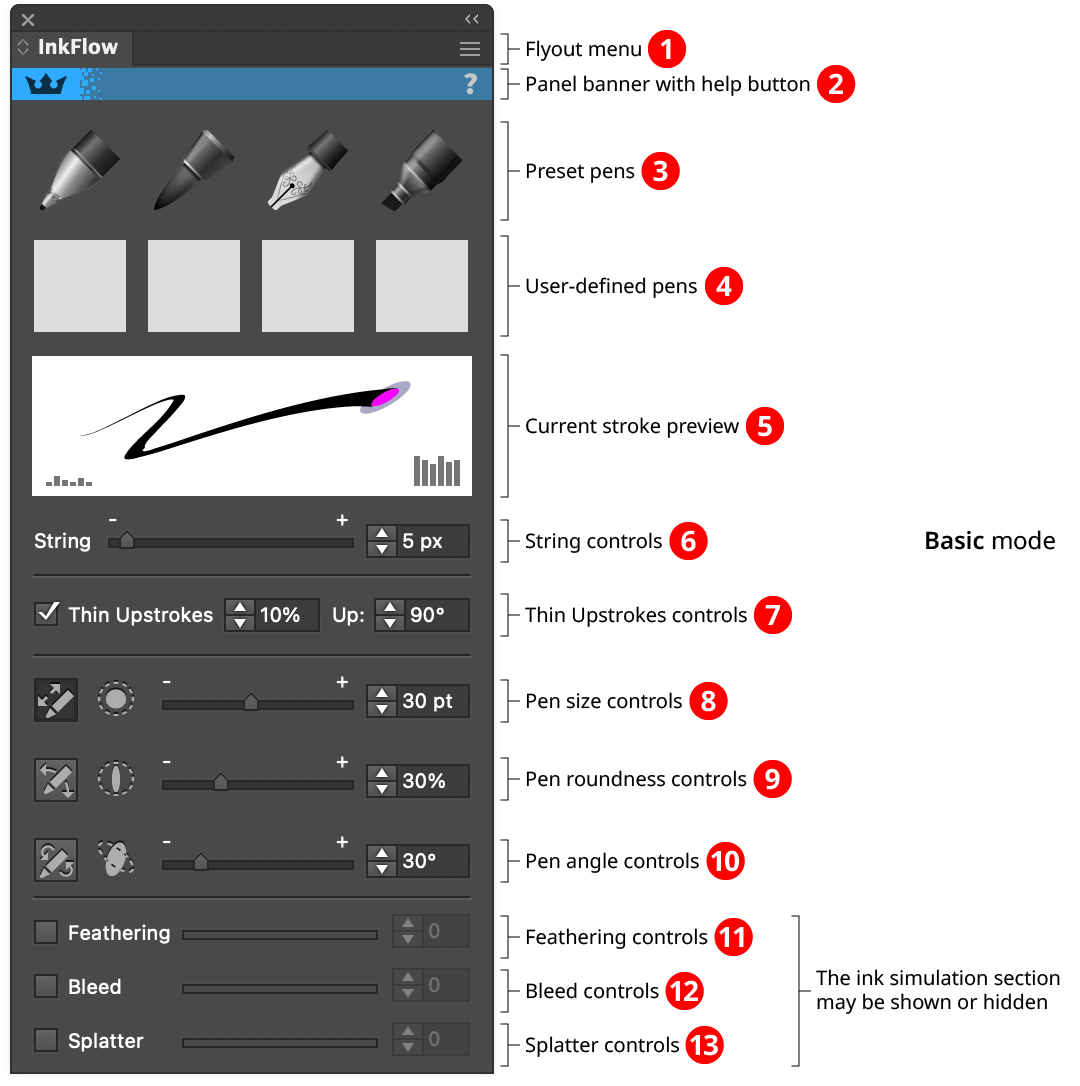
InkFlow Panel (Basic Mode)
1. Flyout menu
See InkFlow Panel: Flyout Menu.
2. Panel banner
The InkFlow panel banner has a help button on the right which opens the help documentation in the Astute Manager. If this does not automatically appear, please ensure your Astute Manager is running first. Also, the panel banner can be clicked to activate the InkFlow tool. This is a quick method of locating the tool within the default Advanced toolbar or a custom toolbar.
3. Preset Pens
InkFlow offers four preset pens with different characteristics. Each may be selected by clicking on the corresponding icon in the top row, which will highlight in blue. Each pen may be customized by selecting it, changing its parameters using the panel controls underneath, and then Option/Alt-clicking on the icon. To reset a preset pen back to its default values, Shift-click on it (or all of the preset pens may be reset by using the panel flyout menu item Reset Standard Pens). If one or more InkFlow strokes are selected when a pen is selected, their strokes will be changed to match the selected pen’s.
a. Ballpoint Pen Preset: The Ballpoint Pen preset is designed to imitate a typical ballpoint pen, with a small round tip, and slight upstroke thinning.
b. Brush Pen Preset: The Brush Pen preset is designed to imitate a fiber-tipped brush, with a larger round tip and high upstroke thinning.
c. Calligraphic Pen Preset: The Calligraphic Pen preset is designed to imitate a shaped pen used for calligraphy. It has a highly-elliptical tip and very high upstroke thinning.
d. Marker Pen Preset: The Brush Pen preset is designed to imitate a wide, chisel-tipped marker. It has a larger, highly-elliptical tip and no upstroke thinning.
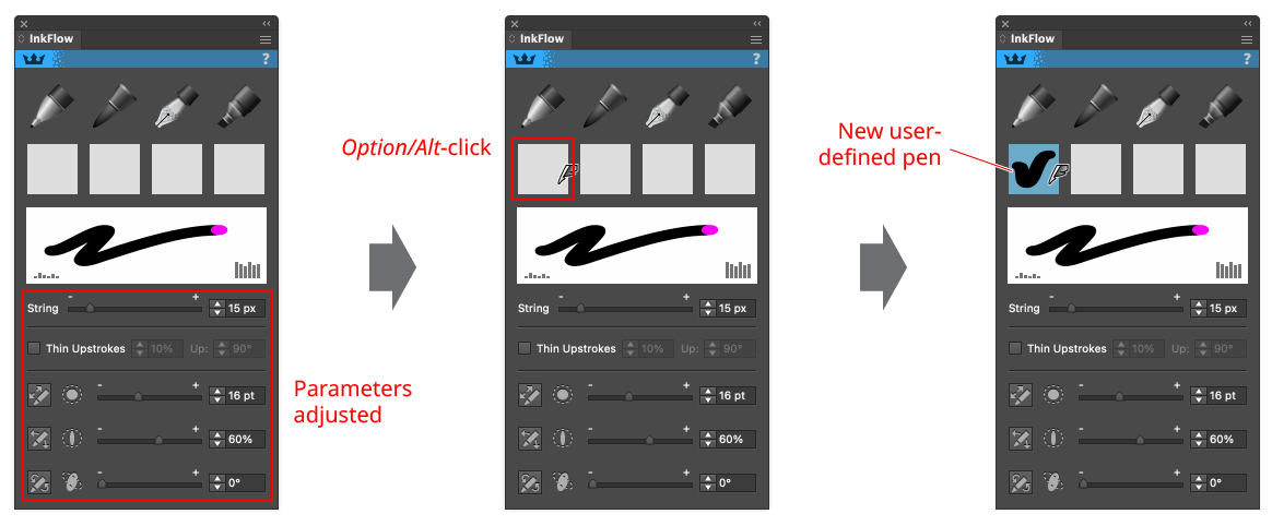
4. User-Defined Pens
You can define up to four pens of your own, which can be recalled by simply clicking on one of the boxes. To define a pen, adjust the panel parameters to their desired values and then Option/Alt-click on one of the boxes to store it. While a user-defined pen cannot be named, an image of its stroke will appear.
InkFlow Panel User Defined Brush
To remove a user-defined pen, Shift-click on its box.
5. Current Stroke Preview
Shows a preview of the stroke that would be produced by the current pen, if it were moved from left to right with increasing pressure. When the pen size is too large to be drawn correctly (more than about 30 pt), it will be shown in a dimmer color around its scaled-down version (drawn in magenta). The preview reflects the Thin Upstrokes parameter, and if enabled, the effective pen size may be smaller than the nominal size.
6. String Controls
The InkFlow cursor is pulled by a virtual “string,” the length of which is specified here, from 1 to 100 pixels. Changing the string length will not change existing selected InkFlow strokes; however, the parameter is saved and recalled with each pen preset. The virtual string acts very similarly to a real string. When it is taut, pulling the string has the effect of dragging the pen in the same direction. However, pushing on the string, or dragging when it is not taut, has no effect on the pen position. A very short string has the effect of stabilizing the pen and filtering out small tremors. This is particularly useful with stylus input devices, which are more susceptible to hand tremor than mice. A longer string changes the characteristics of the pen: it becomes smoother and draws either very shallow curves, or makes tight corners when the string is relaxed and pulled in a different direction.
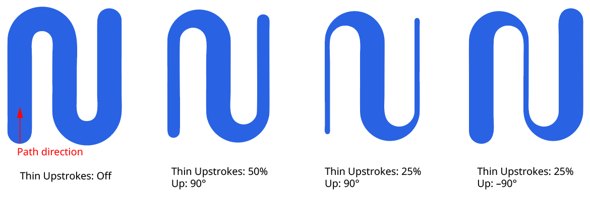
7. Thin Upstrokes Controls
When Thin Upstrokes is enabled, drawing with the pen in the direction specified as “Up” will cause its size to decrease, reflecting the way some physical pens behave, and useful for calligraphy. The amount of thinning can be specified from 1% to 100%, where 20% means a stroke exactly in the “Up” direction would be only 20% of the width of a stroke in the opposite direction (a stroke only partly in the “Up” direction would get partial thinning). By default, the “Up” direction is actually upwards (90°, as specified in Illustrator), but can be changed to any value.
InkFlow Thin Upstroke Examples
8. Pen Size Controls
These controls specify the size of the pen. The slider and value input allow the size to be directly specified, from 1 pt to 1296 pt. The button at left allows pressure control for tablet input devices; when using a mouse it should be kept off. When it is enabled, the specified size value represents the maximum size; the minimum size may be specified by using the control on the Expanded mode panel (see InkFlow Panel Expanded Mode).
9. Pen Roundness Controls
These controls specify the roundness of the pen. The slider and value input allow the roundness to be directly specified, from 1% (an extremely narrow ellipse; nearly a straight line) to 100% (circular). The button at left allows tilt control for tablet input devices; when using a mouse it should be kept off. When it is enabled, the specified roundness value represents the maximum value; the minimum value may be specified by using the control on the Expanded mode panel (see InkFlow Panel Expanded Mode).
10. Pen Angle Controls
These controls specify the angle of the pen tip (which is only relevant if the roundness is set to a value other than 100%). The slider and value input allow the angle to be directly specified. The button at left allows bearing control for tablet input devices; when using a mouse it should be kept off. When it is enabled, the specified angle value represents the default value at neutral bearing; the variance may be specified by using the control on the Expanded mode panel (see InkFlow Panel Expanded Mode).
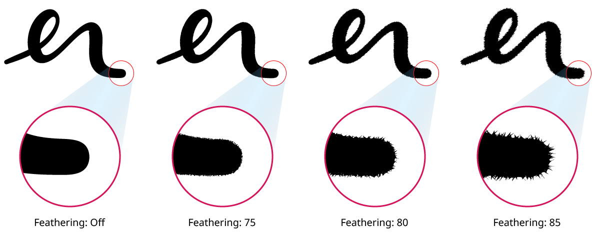
11. Feathering Controls
These controls may be hidden using the panel flyout menu Hide Ink Simulation Controls. Feathering occurs when capillary action causes ink from the pen to be drawn along the fibers of the paper. It creates very fine, thin lines perpendicular or near-perpendicular to the stroke. The InkFlow simulation is designed to be viewed at up to about twice screen resolution, where it creates a fuzziness to the edge and softens it. It doesn’t look realistic at higher zoom levels, due to point count considerations. The feathering value may be set from 0 to 100, with values below about 60 producing fairly subtle results, and values above 85 making the stroke look very spiky.
InkFlow Feathering Examples
12. Bleed Controls
These controls may be hidden using the panel flyout menu Hide Ink Simulation Controls. Bleeding occurs when the pen is brought into contact with and taken off the paper. When a pen is brought into contact with the paper, there is usually a pause, during which time the ink seeps into a circle around the contact point. When it is removed from the paper, it is generally not removed cleanly, and there is an uneven trail during the short period when pen is only partially in contact with the paper. Enabling Bleed in InkFlow simulates both of these effects. For the end of the stroke, the brush trails are randomly generated, and toggling the effect will generate a different look each time.
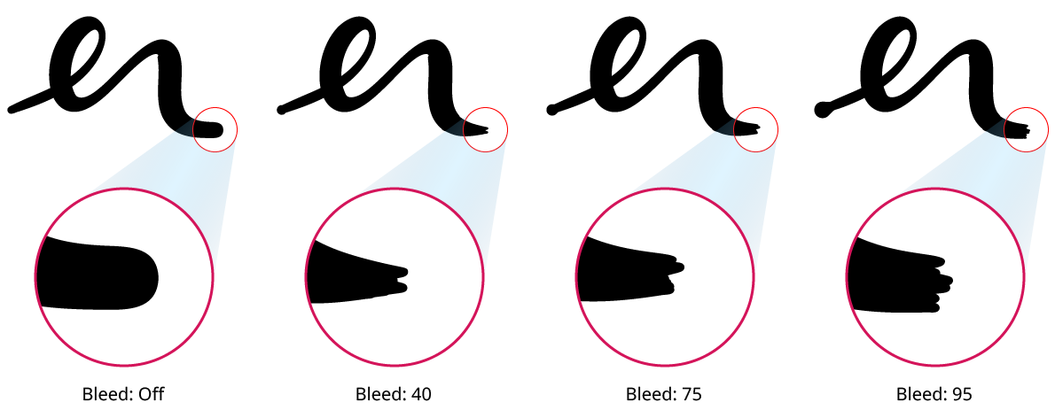
InkFlow Bleed Examples
13. Splatter Controls
These controls may be hidden using the panel flyout menu Hide Ink Simulation Controls. Although splatter generally isn’t seen with modern pens, it does occur in some historical manuscripts. It’s also an artistic way of suggesting real ink. When Splatter is enabled, tiny paths representing droplets surround the stroke, some of them forming teardrop-shaped splashes. The splatter dots are randomly generated, and toggling the effect will generate a different look each time.
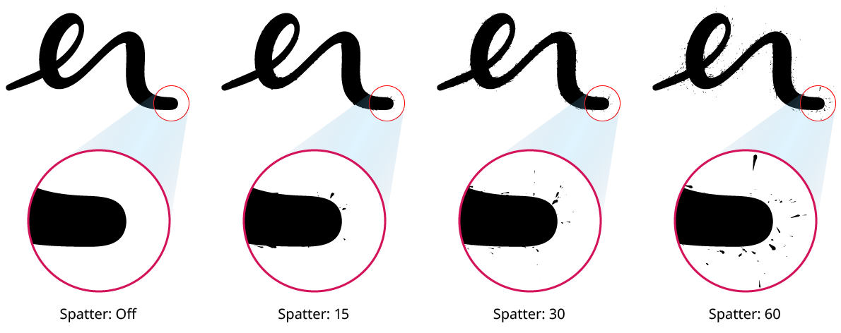
InkFlow Splatter Examples
Illustrator Location:
Illustrator Main Menu > Window > Astute Graphics > Dynamic Sketch > Panel Flyout Menu > Dynamic Sketch Preferences...
Using the flyout menu of the Dynamic Sketch panel, doubleclicking the Dynamic Sketch tool in the toolbox, or pressing the Enter key when the tool is selected will bring up the Dynamic Sketch preferences dialog:
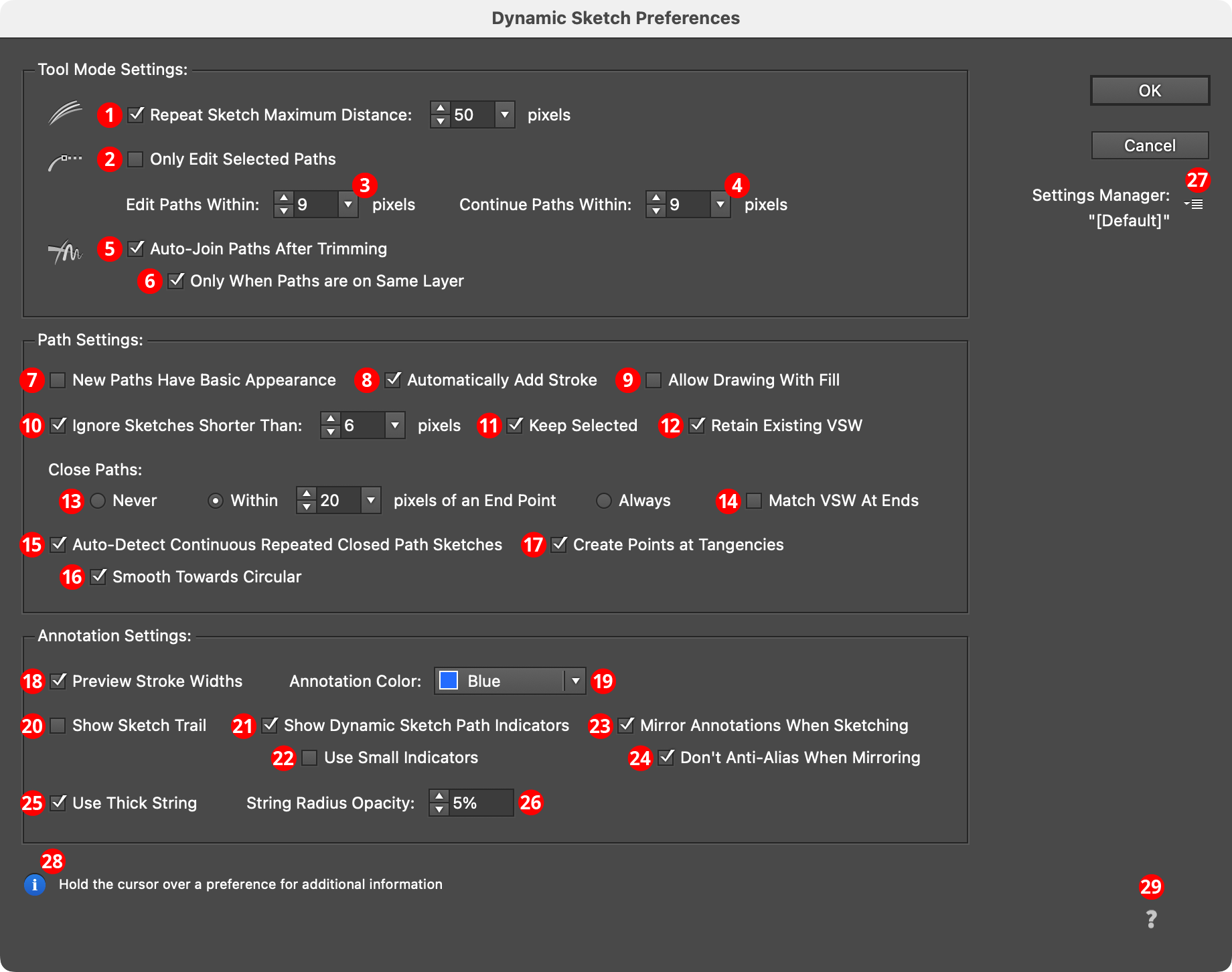
DynamicSketch Preferences
1. Repeat Sketch Traces Maximum Distance
When enabled, repeat sketch traces can only be added to an existing sketch path if the tool’s drag start is within the specified number of pixels of the original start of the path, making it quicker to start a new path some distance away.
2. Only Edit Selected Paths
When enabled, only paths which are already selected can be edited (or continued, or joined). This can make it easier to avoid accidentally editing a path.
3. Edit Paths Within
The maximum distance between the path and the cursor to allow editing of that path to take place. The default value is 9 pixels.
4. Continue Paths Within
The maximum distance between the path endpoint and the cursor to allow continuation of that path to take place. The default value is 9 pixels.
5. Auto-Join Paths After Trimming
Following a manual trim or gesture trim operation, paths with coincident endpoints will be detected and automatically joined, when possible.
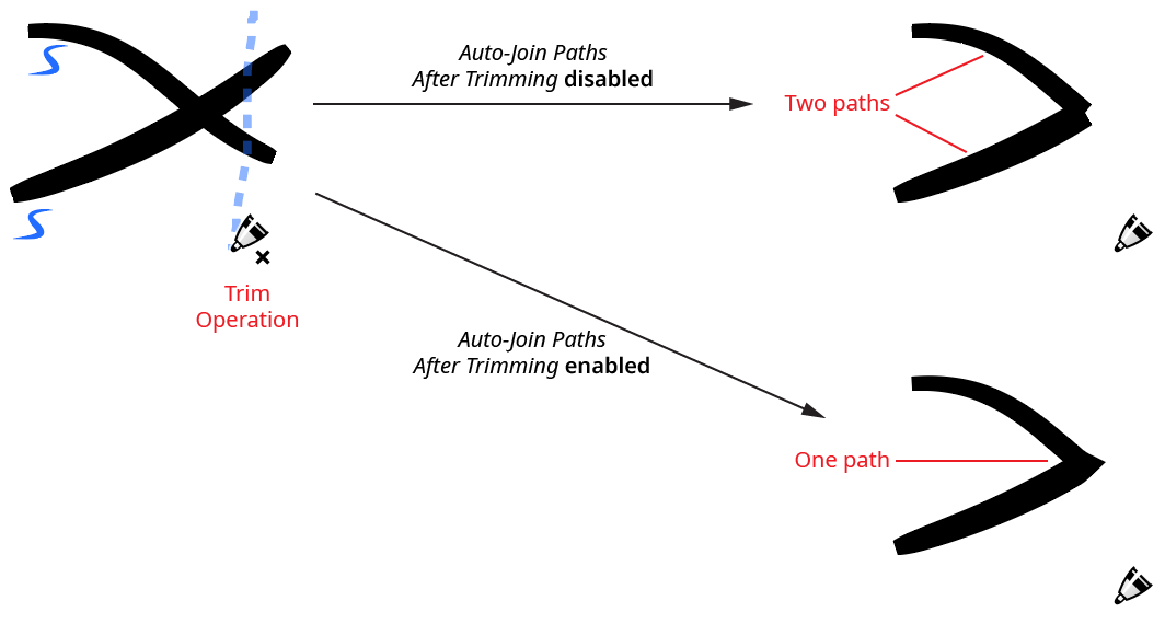
Dynamic Sketch Auto-Join Paths
When paths with variable stroke widths are joined, the width profiles of each section will be preserved as best as possible. Note that this is in contrast to joining the paths with the native Command/Ctrl-J, which instead takes the stroke width profile for the joined path from the topmost of the original paths.
6. Only When Paths Are On Same Layer
Available when Auto-Join Paths After Trimming is enabled, this preference ensures that joining will only occur if the trimmed paths are on the same layer.
7. New Paths Have Basic Appearance
Enabling this preference is the same as enabling the native preference New Art Has Basic Appearance (accessible through the flyout menu of the Appearance panel), except it only applied to the paths created with the Dynamic Sketch tool. To create paths with the current variable stroke width profile, enable both this preference and the Retain Existing VSW preference, and set the Width Input menu to None.
8. Automatically Add Stroke
When enabled, drawing a variable width sketch path when the current appearance has no stroke will automatically add a stroke (black in color) to ensure that the variable width data is retained. Otherwise the Width Input will automatically be set to None.
9. Allow Drawing With Fill
By default, Dynamic Sketch draws paths with a stroke only. If the current appearance includes a fill, then the following warning dialog is displayed:
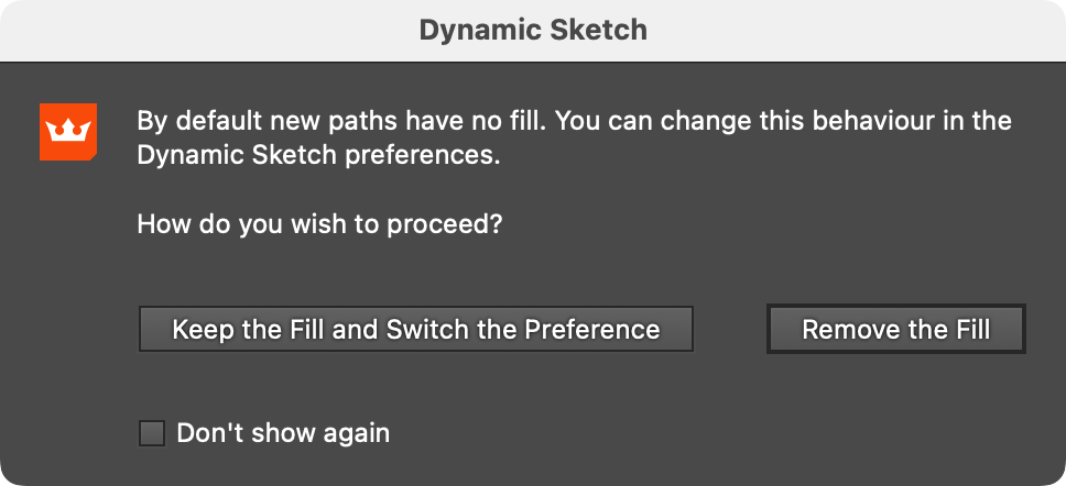
Dynamic Sketch No Fill Warning
Enabling this preference specifies that Dynamic Sketch should keep the fill (if any) when drawing new paths, and the warning dialog will never appear. To always remove the fill after drawing a sketch path without seeing the dialog, enable the “Don’t show again” checkbox and click the “Remove the Fill” button. Fills can still be manually added to any sketch path after it is drawn.
10. Ignore Sketches Shorter Than
When using a tablet, tapping the stylus to click often inadvertently drags the cursor a very short distance as well. To avoid very short sketch paths being created, enable this preference and specify a tolerance value; the default is 6 pixels.
11. Keep Selected
When enabled, drawing a new Dynamic Sketch path will not deselect the previously drawn path.
12. Retain Existing VSW
When enabled, drawing a sketch path with the Width Input menu set to None will retain the existing variable stroke width profile. The path, however, will not remain dynamic.
13. Close Paths
There are three options regarding closing paths when drawing a sketch path:
Never: Paths will never be closed, even if the ending point is very close to the starting point.
Within __ pixels of an endpoint: If the cursor ends within the specified distance of the starting point, the path will be closed. The cursor will show the “link” badge when this distance has been reached.
Always: The path will always be closed, using a straight segment between the ending and starting points.
14. Match VSW At Ends
When drawing a closed path with a variable stroke width, the widths will be adjusted so that the join point is smooth:
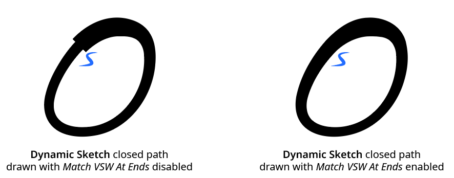
Dynamic Sketch Match Variable Stroke Width
15. Auto-Detect Continuous Repeated Closed Path Sketches
When enabled, closed sketch paths drawn so that they loop on top of themselves reasonably consistently (and at least twice) will be converted to a single, smooth closed path:
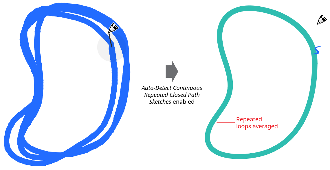
Dynamic Sketch Auto-Detect Continuous Repeated
16. Smooth Towards Circular
If Auto-Detect Continuous Repeated Closed Path Sketches is enabled, then enabling this preference allows the Smoothness setting to act as a blending parameter (in addition to its role in smoothing the stroke widths). In this case if the smoothness is set to 0%, the path will simply be an average of the repeated loops; the closer the smoothness is moved towards 100%, the closer the path will conform to a perfect circle.
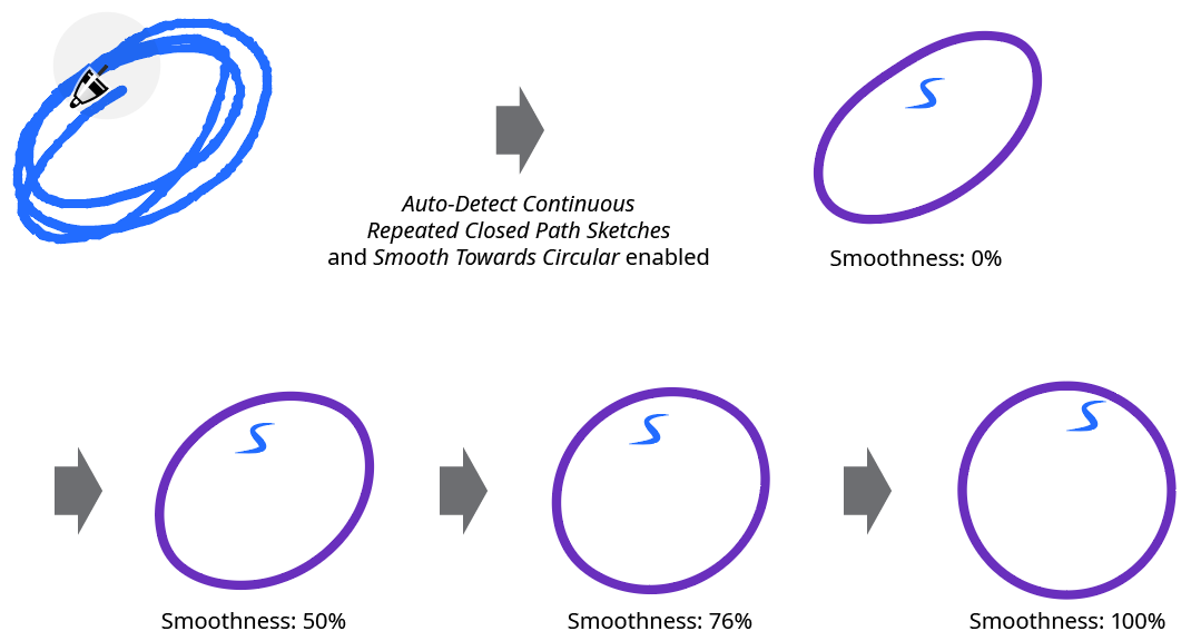
Dynamic Sketch Smooth Towards Circular
17. Create Points At Tangencies
When enabled, Dynamic Sketch will place the path’s anchor points, where possible, at positions on the path where the path is tangent to the vertical and horizontal axes (taking into account the current general constrain angle):
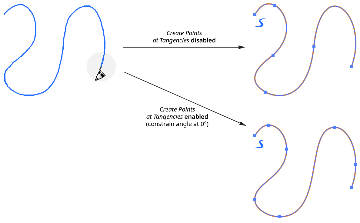
Dynamic Sketch Creates Points at Tangencies
18. Preview Stroke Widths
When enabled (the default), Dynamic Sketch will annotate an approximation of the width of the stroke while the sketch path is being drawn. When disabled, the path is only annotated with a 1-pixel wide line, like the native Pencil tool. This preference can be toggled on the fly (while dragging) with the S key.
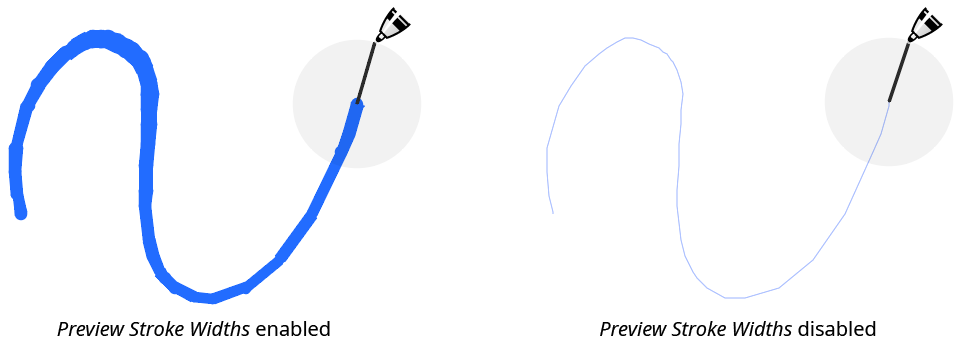
Dynamic Sketch Preview Stroke Width
19. Annotation Color
The menu allows a choice of annotation colors, from among blue (default), red, magenta, green, cyan, and black. This preference can be changed on the fly (while dragging) with the C key (each press of the key advances to the next color). If Preview Stroke Widths is disabled, or Show Sketch Trail is enabled, the sketch traces are always shown in light blue.
20. Show Sketch Trail
When enabled, the sketch traces (points laid down as the cursor was moved) are annotated in light blue even after the mouse button is released, thereby allowing a comparison of the resulting path with the original input trace(s).
21. Show Dynamic Sketch Path Indicators
When enabled, each active Dynamic Sketch path will be annotated with a small “swoosh” icon adjacent to its starting point (the default color is blue, but can be changed using the Annotation Color preference).
22. Use Small Indicators
The path indicators will be smaller in size that the default indicators.
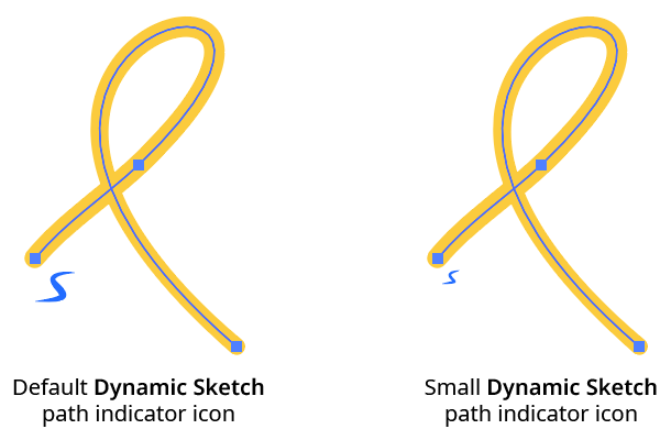
Dynamic Sketch Path Indicators
23. Mirror Annotations When Sketching
When using Astute Graphics’ MirrorMe plugin, and drawing into an active sector of mirroring axes applied to a layer, Dynamic Sketch can mirror its annotations during the sketching operation. This may result in slower performance. This preference can be toggled on the fly (while dragging) with the M key.
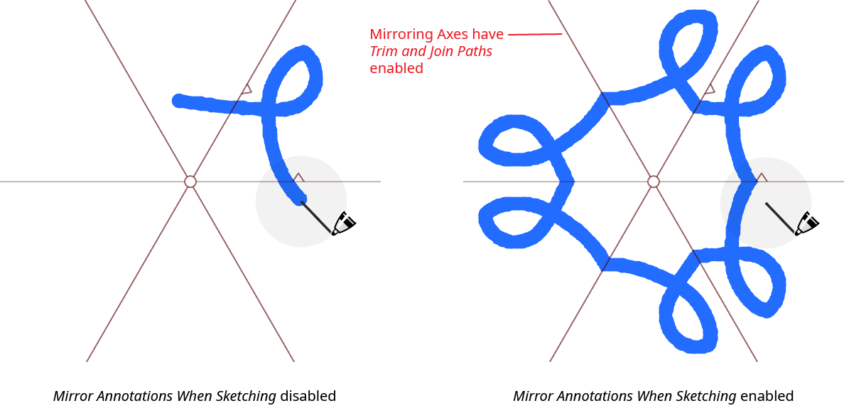
Dynamic Sketch Mirror Annotations
24. Don’t Anti-Alias When Mirroring
When using mirrored annotations, performance can be sped up somewhat by enabling this preference.
25. Use Thick String
When using the pulled cursor, annotates the string with a thicker line, which is easier to see on high-resolution monitors.
26. String Radius Opacity
When using the pulled cursor, controls the opacity of the “disc” which indicates the current length of the string (by its radius). The disc can be useful when making a sharp corner and the string has been made slack; when the cursor is subsequently moved, it indicates when the cursor will begin drawing again: when it reaches the edge of the disc. The default opacity is 5%.
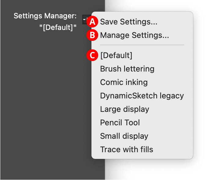
27. Settings Manager
The Settings Manager popup menu provides access to saving, managing, and applying preference settings.
Dynamic Sketch Settings Manager
A. Save Settings...
When you save the preference settings, all of the current settings in the preferences dialog are captured in a file which can be recalled later. The file name may be specified.
B. Manage Settings...
Brings up the Manage Settings dialog, which lets you rename or delete existing settings files:
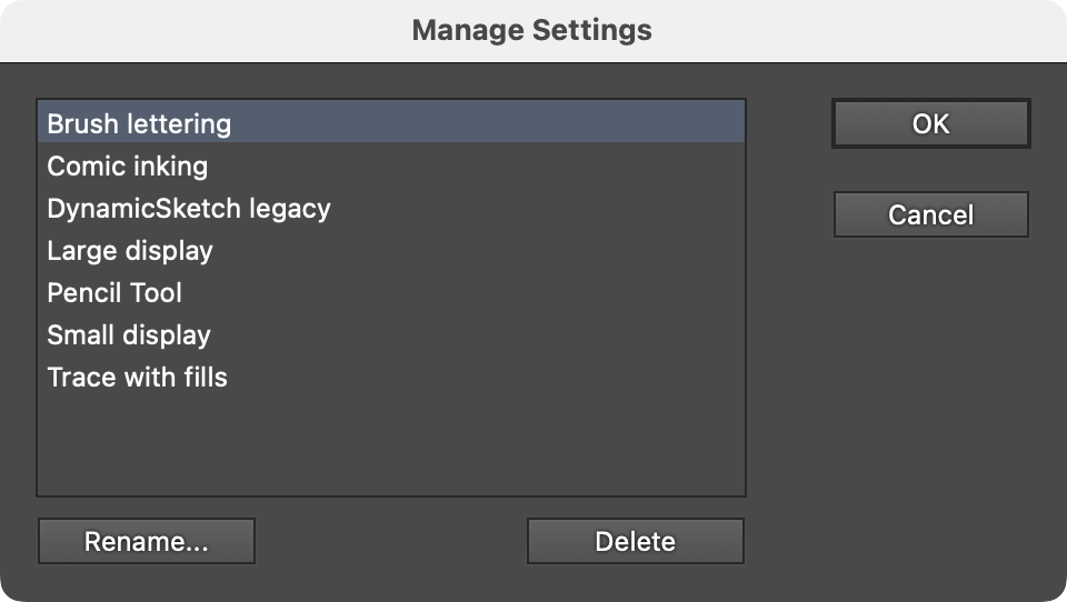
Dynamic Sketch Manage Settings Dialog
C. Settings List
Choosing a settings file from this list will change the preference settings to match the state of the dialog when the settings file was saved (or, the case of “[Default]”, to the default values).
28. Informational area
Shows a brief description of each preference control when the cursor is being hovered over it.
29. Help Button
Opens the help documentation in the Astute Manager. If this does not automatically appear, please ensure your Astute Manager is running first.
Illustrator Location:
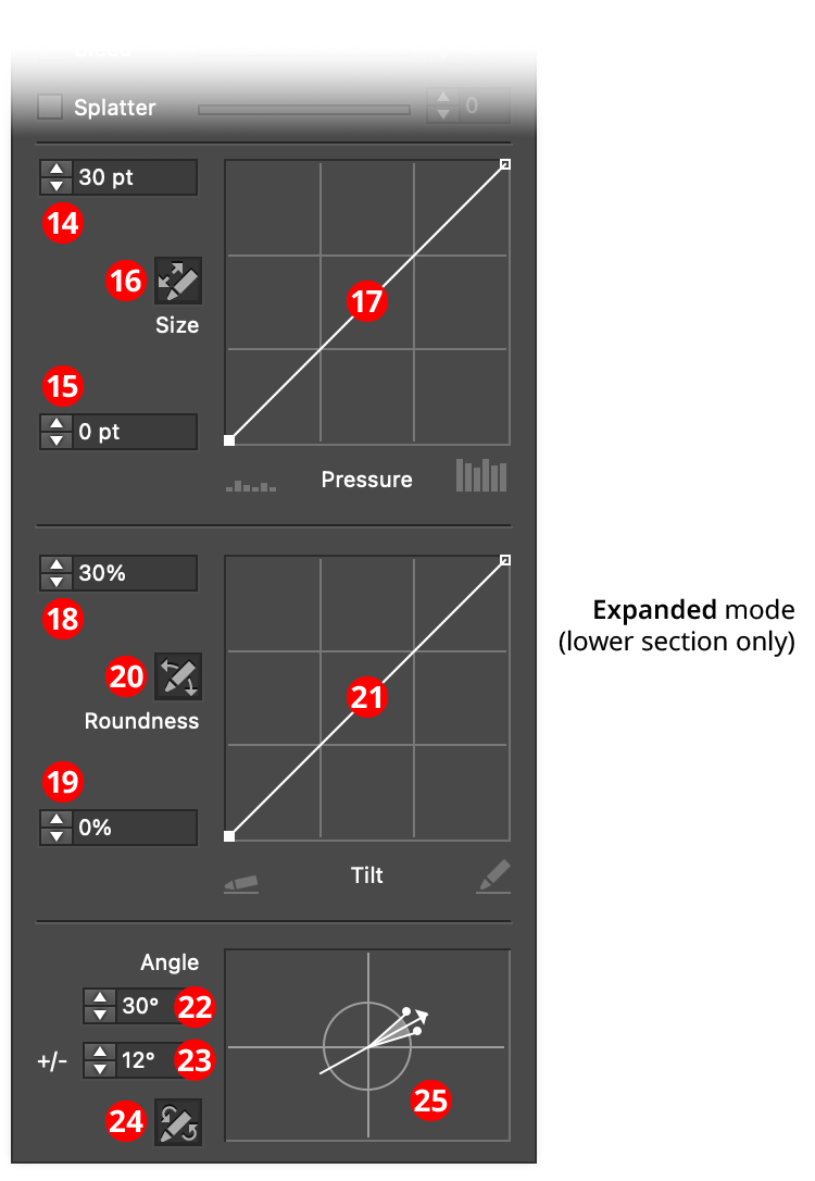
InkFlow Panel (Expanded Mode)
14. Size/Maximum Size
If pressure control is off, this value specifies the size of the pen. Otherwise, it specifies the maximum size that the pen can reach, at a pressure which is dependent on the size-pressure curve.
15. Minimum Size
The minimum size that the pen can reach, at a pressure which is dependent on the size control graph.
16. Size-Pressure Button
When toggled into the enabled state (the button will be dark), the pen size is variable, and based on the amount of pressure created by a stylus or similar input device.
17. Size Control Graph
Specifies the relationship between the maximum and minimum size values and the input pressure. The horizontal axis represents the pressure, from 0% to 100%, while the vertical axis represents the brush size, specified by the maximum and minimum value inputs. With the default diagonal line, the relationship is a linear one, with minimum pressure yielding minimum size and maximum pressure yielding maximum size. Nodes on the curve may be moved simply by clicking and dragging them. A new node may be added by clicking at a spot along the curve which does not already have a node. Nodes (except the ones at the beginning and the end of the curve) may be deleted by dragging them off the graph area.
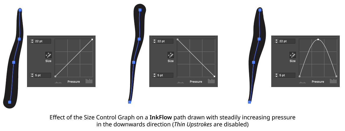
InkFlow Size Control Graph Examples
18. Roundness/Maximum Roundness
If tilt control is off, this value specifies the roundness of the pen. Otherwise, it specifies the maximum roundness that the pen can reach, at a tilt which is dependent on the roundness-tilt curve.
19. Minimum Roundness
The minimum roundness that the pen can reach, at a tilt which is dependent on the roundness-tilt curve.
20. Roundness-Tilt Button
When toggled into the enabled state (the button will be dark), the pen roundness is variable, and based on the amount of tilt reported by a stylus or similar input device.
21. Roundness Control Graph
Specifies the relationship between the maximum and minimum roundness values and the input tilt. The horizontal axis represents the tilt, from almost flat to completely upright, while the vertical axis represents the brush roundness, specified by the maximum and minimum value inputs. With the default diagonal line, the relationship is a linear one. Nodes on the curve may be moved simply by clicking and dragging them. A new node may be added by clicking at a spot along the curve which does not already have a node. Nodes (except the ones at the beginning and the end of the curve) may be deleted by dragging them off the graph area.
22. Angle/Base Angle
If bearing control is off, this value specifies the angle of the pen tip. Otherwise, it specifies the base angle to which an additional amount is added or subtracted, depending on the bearing and the angle-bearing curve.
23. Angle Variability
The maximum variability in angle (from 0° to 90°) that can be created by different bearing values.
24. Angle-Bearing Button
When toggled into the enabled state (the button will be dark), the pen angle is variable, and based on the bearing value reported by a stylus or similar input device.
25. Angle Widget
Visualizes the angle and angle variability settings, and allows them to be edited graphically by dragging the angle arrowhead or the variability dots. An overly-wide spread will tend to create undesirable results because of the speed at which stylus bearing can change, and interpolation issues.
Illustrator Location:
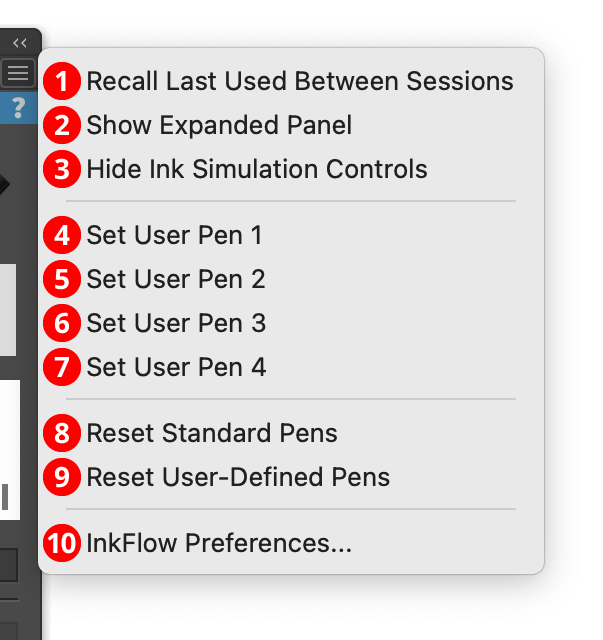
InkFlow Panel Flyout Menu
1. Recall Last Used Between Sessions
When enabled (preceded by a checkmark), all of the parameters shown on the InkFlow panel will be retained between launches of Illustrator. Otherwise, they are reset to their default values on each launch.
2. Show Expanded Panel
When enabled (preceded by a checkmark), additional controls for the pen size, roundness, and angle are displayed. These are only useful when using a tablet that supports pressure, tilt, and/or bearing as the input device.
3. Hide Ink Simulation Controls
The feathering, bleed, and splatter controls can be shown or hidden on the panel using this menu item. When the controls are hidden, the menu item will change to Show Ink Simulation Controls.
4. Set User Pen 1
5. Set User Pen 2
6. Set User Pen 3
7. Set User Pen 4
Each menu item sets the corresponding user-defined pen, using the current panel parameters. This is equivalent to Option/Alt-clicking on the corresponding box (see InkFlow Panel Basic Mode: User-Defined Pens).
8. Reset Standard Pens
Resets all four of the standard (top-row) pens to the parameters that they shipped with (losing any customization that may have been done to them). To reset just one standard pen, Shift-click on its icon.
9. Reset User-Defined Pens
Resets all four of the user-defined (second-row) pens to empty slots. To reset just one user-defined pen, Shift-click on its icon.
10. InkFlow Preferences...
Brings up the Preferences dialog (see InkFlow: Preferences).
Illustrator Location:
Illustrator Main Menu > Window > Astute Graphics > InkScribe
The menu item to show and hide the InkScribe panel can be found in the main menu under Window > Astute Graphics > InkScribe. The InkScribe panel contains the same ten point and path buttons that can appear on the virtual panel. It also allows control over various options that affect the InkScribe tool, such as whether connector recognition is on or off, or whether paths can be joined together.
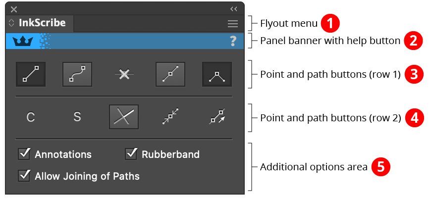
InkScribe Panel
1. Flyout menu
See InkScribe Panel: Flyout Menu.
2. Panel banner
The InkScribe panel banner has a help button on the right which opens the help documentation in the Astute Manager. If this does not automatically appear, please ensure your Astute Manager is running first.
3. Point and Path Buttons (row 1)
a. Straight Segment Button: When continuing a path, and the cursor is clicked (without dragging) to create a new anchor point, if the straight segment button is in its enabled state (shaded), then the segment created will be straight, with no handles (any Out handle on the previous anchor point will automatically be removed).
b. Curved Segment Button: When continuing a path, and the cursor is clicked (without dragging) to create a new anchor point, if the curved segment button is in its enabled state (shaded), then the segment created will be curved, with a new Out handle automatically added to the previous anchor point. The exception is when the previous segment was straight, and the tool preference Continuing From Straight to Curve is set to Keep Handle Retracted, in which case the segment remains straight.
c. Smart Remove Point Button: Removes the selected anchor point(s) and adjusts the handles of the points on either side of the removed point(s) so the resulting path shape is as close to the original as possible (see example in InkScribe Tool: Existing Point Operations). To remove one or more anchor points without adjusting handles, hold down Option/Alt when clicking the button.
d. Smooth Point Button: Changes all selected anchor points to smooth points. By default, this also adds new handles to these points so they all have two opposed handles. This is useful for creating a path that runs smoothly through the points:
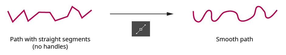
InkScribe Panel - Smoothing Example
The algorithm that InkScribe uses to create new handles is as follows: If a point already has one handle, its second handle is created by mirroring the existing handle. If a point has no handles, the new handle angle is calculated by bisecting the angle formed by the previous point, the point in question, and the next point, and taking its perpendicular. The new handle length is calculated by taking the lesser of the distances from the point in question to the previous and next points, and multiplying by 0.3905. This ratio causes a square to be turned into a circle when its points are smoothed. Handles of endpoints of open paths, if created, are adjusted to aim towards the next/previous handle.
e. Corner Point Button: Changes all selected anchor points to corner points. No handles are created or changed.
4. Point and Path Buttons (row 2)
a. Connector Point Recognition Button: Enables or disables Connector Point recognition. When the “C” symbol is dim, connector point recognition is off and the InkScribe tool will not afford any special handling to points which qualify as connectors. See InkScribe Tool: Connector Points.
b. Smart Smooth Button: Enables or disables “Smart Smooth”, a feature of the InkScribe tool which allows you to convert a corner point into a smooth point simply by dragging one of the point’s handles to be opposite the other (within a certain tolerance). A small red “S” annotation is drawn over points which are being aligned this way. The threshold angle value can be specified in the Preferences dialog.
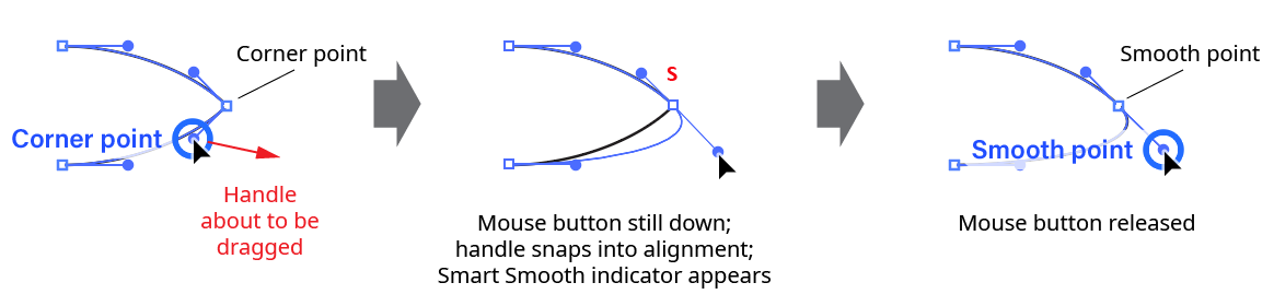
InkScribe Panel - Smart Smooth
c. Constrain Angle Button: When this button is in its enabled state (shaded), new points can only
be created at 45° angle increments from the previous point (honoring the constrain angle). Existing points that are moved can only be moved along these same angles. New handles and handles which are edited must also have these same angles.
d. Retract Handles Button: Retracts all of the handles on the selected anchor point(s). Point types are not changed. Holding down Option/Alt while clicking the button activates an alternate function: it swaps the positions of the In and Out handles on each selected point.
e. Close/Join Paths Button: Closes one or more open paths that are at least partially-selected, honoring any out-facing handles which may exist on the path’s endpoints. But if the selection consists of exactly two endpoints on two open paths, then the two paths are instead joined together.
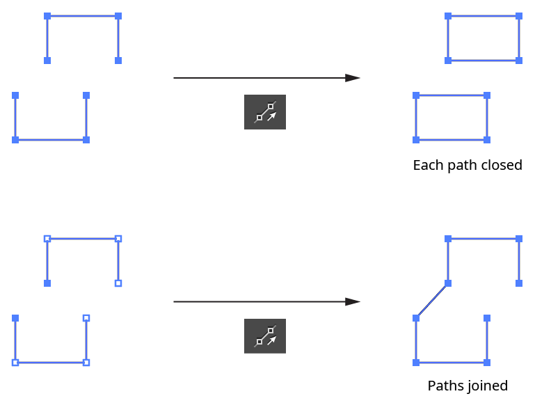
InkScribe - Close Join Path Example
5. Additional Options Area
a. Annotations: Enables or disables the virtual panel annotation which appears when a single anchor point is selected.
b. Rubberband: Enables or disables the “rubberband” preview of the segment about to be drawn.
c. Allow Joining of Paths: When disabled, continuing one path onto the endpoint of another path will not automatically join the first path to the second (however, open paths can still be closed).