 InkFlow Panel Expanded Mode

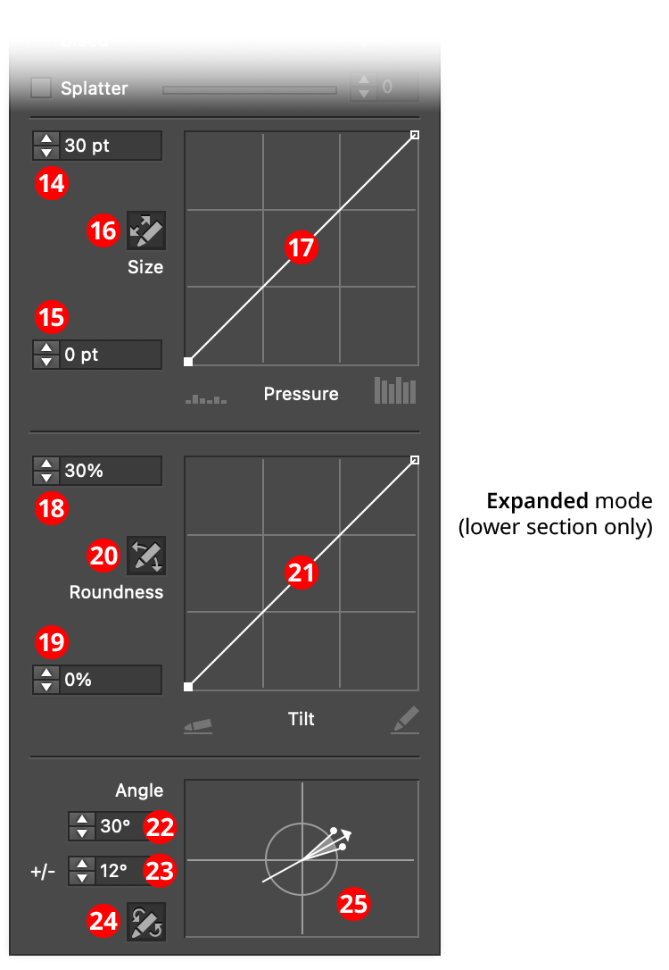
InkFlow Panel (Expanded Mode)
14. Size/Maximum Size
If pressure control is off, this value specifies the size of the pen. Otherwise, it specifies the maximum size that the pen can reach, at a pressure which is dependent on the size-pressure curve.
15. Minimum Size
The minimum size that the pen can reach, at a pressure which is dependent on the size control graph.
16. Size-Pressure Button
When toggled into the enabled state (the button will be dark), the pen size is variable, and based on the amount of pressure created by a stylus or similar input device.
17. Size Control Graph
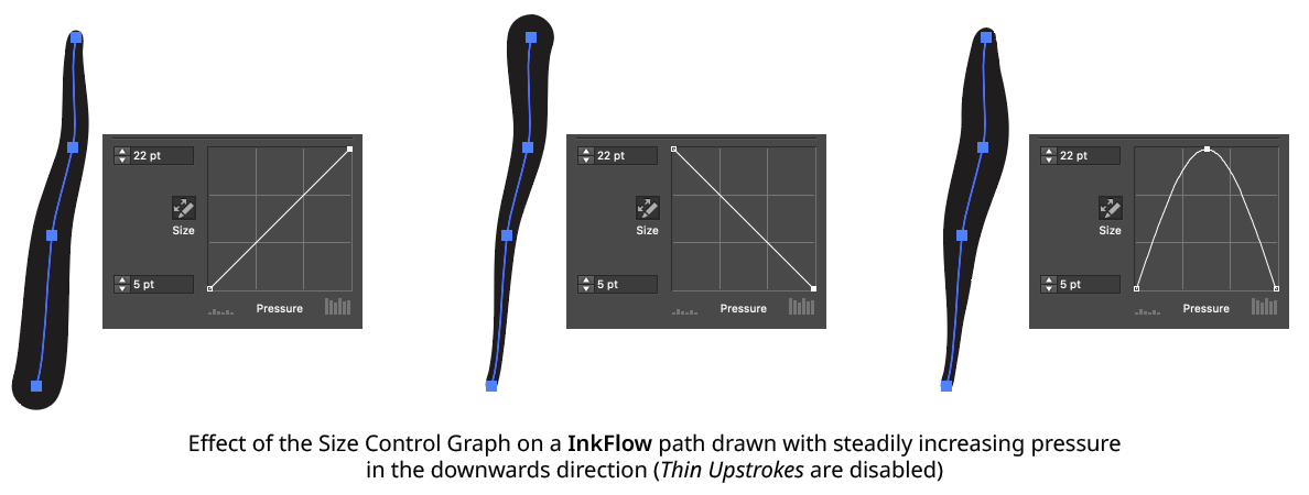
Specifies the relationship between the maximum and minimum size values and the input pressure. The horizontal axis represents the pressure, from 0% to 100%, while the vertical axis represents the brush size, specified by the maximum and minimum value inputs. With the default diagonal line, the relationship is a linear one, with minimum pressure yielding minimum size and maximum pressure yielding maximum size. Nodes on the curve may be moved simply by clicking and dragging them. A new node may be added by clicking at a spot along the curve which does not already have a node. Nodes (except the ones at the beginning and the end of the curve) may be deleted by dragging them off the graph area.

InkFlow Size Control Graph Examples
18. Roundness/Maximum Roundness
If tilt control is off, this value specifies the roundness of the pen. Otherwise, it specifies the maximum roundness that the pen can reach, at a tilt which is dependent on the roundness-tilt curve.
19. Minimum Roundness
The minimum roundness that the pen can reach, at a tilt which is dependent on the roundness-tilt curve.
20. Roundness-Tilt Button
When toggled into the enabled state (the button will be dark), the pen roundness is variable, and based on the amount of tilt reported by a stylus or similar input device.
21. Roundness Control Graph
Specifies the relationship between the maximum and minimum roundness values and the input tilt. The horizontal axis represents the tilt, from almost flat to completely upright, while the vertical axis represents the brush roundness, specified by the maximum and minimum value inputs. With the default diagonal line, the relationship is a linear one. Nodes on the curve may be moved simply by clicking and dragging them. A new node may be added by clicking at a spot along the curve which does not already have a node. Nodes (except the ones at the beginning and the end of the curve) may be deleted by dragging them off the graph area.
22. Angle/Base Angle
If bearing control is off, this value specifies the angle of the pen tip. Otherwise, it specifies the base angle to which an additional amount is added or subtracted, depending on the bearing and the angle-bearing curve.
23. Angle Variability
The maximum variability in angle (from 0° to 90°) that can be created by different bearing values.
24. Angle-Bearing Button
When toggled into the enabled state (the button will be dark), the pen angle is variable, and based on the bearing value reported by a stylus or similar input device.
25. Angle Widget
Visualizes the angle and angle variability settings, and allows them to be edited graphically by dragging the angle arrowhead or the variability dots. An overly-wide spread will tend to create undesirable results because of the speed at which stylus bearing can change, and interpolation issues.
