 Dynamic Measure
The Dynamic Measure component of VectorScribe consists of the Dynamic Measure tool and the Dynamic Measure panel. It allows you to make precise measurements of your artwork, including distances along paths, areas of paths, curvatures of radius, path angles, the shortest distance between two paths, and more. Measurements may be made in any scale and with any units, and may be converted from annotations to artwork with a single click.
Dynamic Measure Tool
Dynamic Measure Tool Location
The Dynamic Measure tool is used to create, edit, delete, or convert measures. It has a cursor like a small crosshair. To make a measurement, click once at the start point and again at the end point (this method can be changed to click-and-drag in the preferences). The start and end points will be connected by a thin line (red by default), and an arrow showing the direction. Measurement values appear both in the Info panel and, by default, in a box next to the cursor.
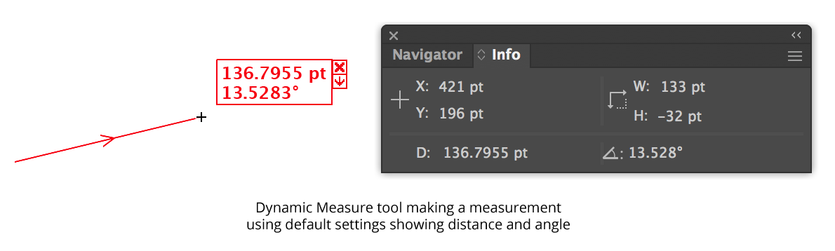
Dynamic Measure Overview
Information about the path under the cursor is also displayed by default, using a feature called “Hover Measure” (see below).
New Measures
After the mouse button is released, the default behavior is for the measure to remain on the screen indefinitely, even when the Dynamic Measure tool is deselected. Measures are undoable, and are saved with the document. To cancel a measure in progress, press the Esc key while moving the cursor. To constrain a measure to horizontal and vertical directions (as well as 45° increments), hold down Shift when measuring. To snap while constraining or to constrain a measure to the general constrain angle, turn on Smart Guides.
By default, Dynamic Measure snaps the cursor to paths and guides, anchor points, and handles and draws a ring around the cursor to indicate this. When Smart Guides are enabled, Dynamic Measure will also snap to path intersections and centers, page edges, etc. A small triangle on the snapping ring(s) indicates path direction. Selected paths take precedence over unselected path when both are within snapping range.
In addition to straight-line distance, Dynamic Measure can measure the distance between two places on a path by enabling the “Distance Along Path” setting. For open paths, this measurement value is indicated by the heading ”DP:”. In the case of a closed path, there are two ways we can go “along” the path to get from the first location to the second, so the values are abbreviated as “DWP” (Distance With Path, i.e., in the direction of the path) and “DAP” (Distance Against Path, i.e. against the direction of the path):
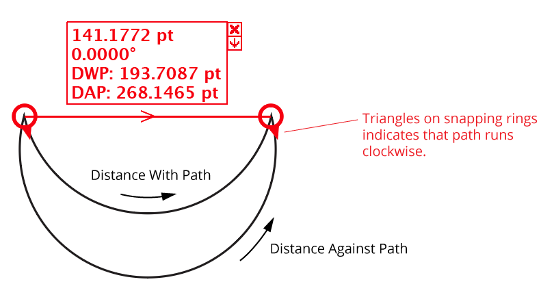
Dynamic Measure Distance along a path
Editing Measures
An existing Dynamic Measure can be edited by pressing Option/Alt with the cursor hovering over one of the endpoints. An annotation with four arrows will appear, indicating that the endpoint may be relocated by clicking. Afterwards, the measure acts similarly to a new measure.
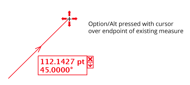
Dynamic Measure Moving existing measures
Deleting Measures
Dynamic Measures can be deleted using the tool in two ways. The first is the simply click the “Delete Measure Button,” which is the small “X” icon that appears by default at upper right. The second way is to hover the cursor over the text area of the measure and hold down the Option/Alt key. The measure will become lighter, and clicking will delete it. If Shift is also held down, then all existing measures will be deleted:
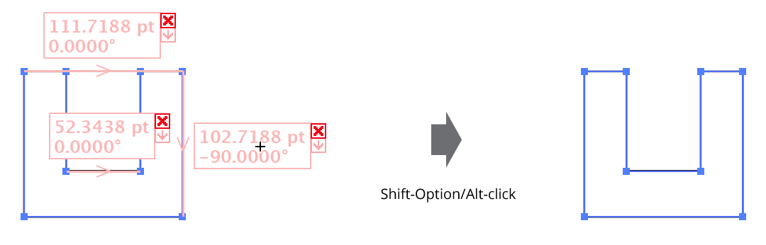
Deleting all Dynamic Measures
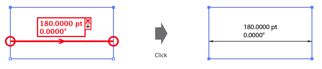
Converting Measure to Artwork
To convert a Dynamic Measure into editable artwork, click the “Convert Measure Button,” which is the small icon that looks like a down arrow. While the cursor is over the button, the measure and its data will become bolder as a visual indication of the convert operation.
Dynamic Measure - Converting measures into artwork
To convert all existing measures into artwork, hover the cursor over the text area of any measure and click with the Shift key held down.
The new art is created in a new layer at the top of the layer stack named “Dynamic Measure” (unless such a named layer already exists, in which case that existing layer is used). Each measure is created as a separate group, making it easy to hide or delete one. When first created, the “Dynamic Measure” layer is locked by default, but if you unlock it, it will be left that way.
By default, Dynamic Measure uses a 0.25 pt black rule for the measure line and arrowheads and 8pt/8pt type (with all other characteristics being inherited from the Normal style) for the text data. Dynamic Measure creates both a new graphic style and a new character style for these items the first time you convert measures to paths, both with the name “Dynamic Measure” (unless styles with this name already exist, in which case they are used as is). You can therefore change the look of all of the converted measures — for instance, color, thickness of the line, type style — by simply editing these styles.
HoverMeasure
Dynamic Measure can display information about paths, anchor points, and handles simply by hovering the cursor over the item of interest. The fields which are displayed are specified in the preferences dialog. By default, they include path information (type and number of points); length of the path segment; length of the entire path; coordinates of anchor points and handles; and length and angle of handles.
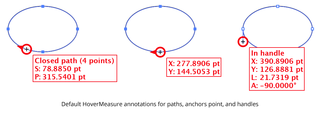
Dynamic Corners HoverMeasure
The path does not need to be selected; however, selected paths take precedence over unselected paths, even if they are underneath them.
Curve Normals
If you enable the display of Curve Normals in the preferences, Dynamic Measure can draw these normals when hovering over a path while holding down Shift. The number of normals is controlled by the “Divisions” setting in the preferences.
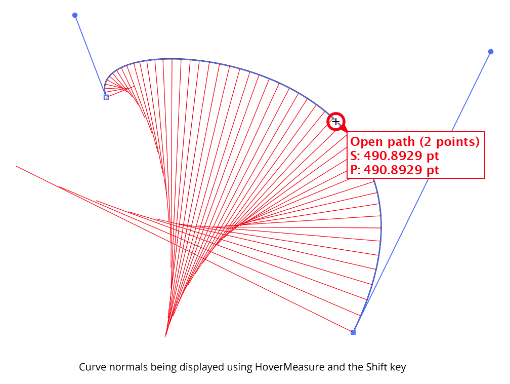
Dynamic Measure Curve Normals Example
To see the curve normal at the cursor point only, hold down Option/Alt rather than Shift. The single curve normal is drawn in blue. Or, you can hold Shift+Option/Alt to see both.
Each line has a length equal to the radius of curvature at the point where the line touches the curve; each is angled normal (perpendicularly) to the curve at that same point. The outer ends of the lines therefore trace out the evolute of the curve. The lines are spaced according to the changing t-parameter of the bezier curve, which changes faster in flatter parts of the curve. You can convert the curve normals into actual paths by clicking while they are being displayed. They will be created as a group at the back of the current layer, with a line style of black, 0.25 pt. They can, of course, be edited like any other artwork afterwards.
Dynamic Measure Panel
The Dynamic Measure panel is used in conjunction with the tool to change displayed parameters, change the scale and units, and measure the closest distance between two paths.
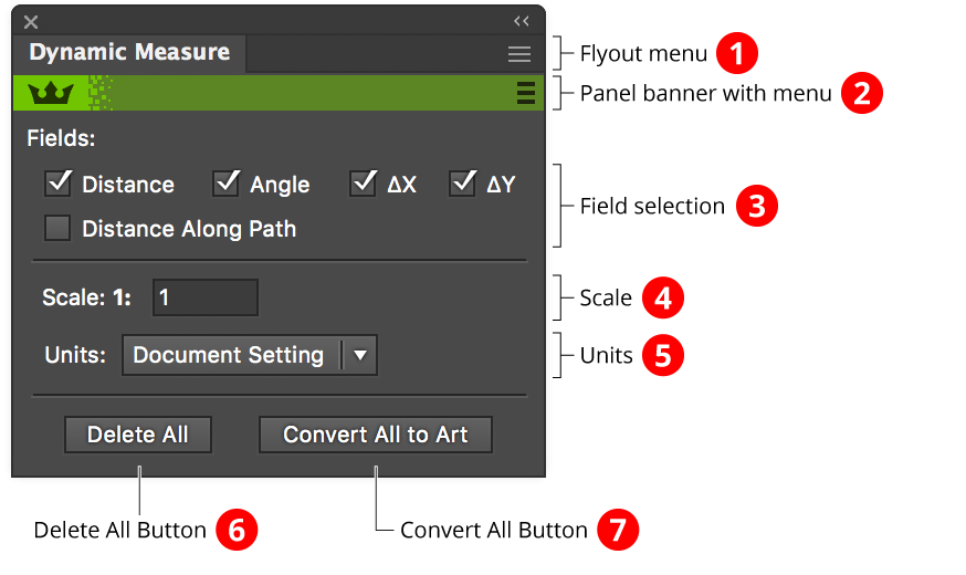
Dynamic Measure Panel Overview
1. Flyout menu
See Dynamic Measure Panel: Flyout Menu.
2. Panel banner
The help button on the right opens the help documentation in the Astute Manager. If this does not automatically appear, please ensure your Astute Manager is running first.
Click on the other area of the color bar to activate the Dynamic Measure tool. This is a quick method of locating the tool within the default Advanced toolbar or a custom toolbar.
3. Field Selection
Specifies which the fields which are displayed for each Dynamic Measure (existing and new). ∆X and ∆Y (also notated as dX and dY depending on the preferences) are the horizontal and vertical components of the measure. Distance Along Path is only valid when the measure starts and ends on a path.
4. Scale
Specifies the scale (multiplier) for displayed measurement values, between 0.000001 and 1,000,000. If, for example, you are creating a map with the scale of 1” equals 1 mile, the scale would be set to the number of inches in 1 mile (5280 × 12 = 63360).
5. Units
Specifies the units for displayed measurement values, from the following: Micrometers, Pixels, Points, Millimeters, Picas, Centimeters, Inches, Feet and inches, Meters, Kilometers, Miles and feet, and Miles (decimal). When set to “Document Setting”, the units will be picked up from the units used in the open document.
6. Delete All Button
Deletes all Dynamic Measures in the document. The Dynamic Measure tool does not need to be active.
7. Convert All Button
Converts all Dynamic Measures in the document to artwork. The Dynamic Measure tool does not need to be active.
Dynamic Measure Panel Flyout Menu
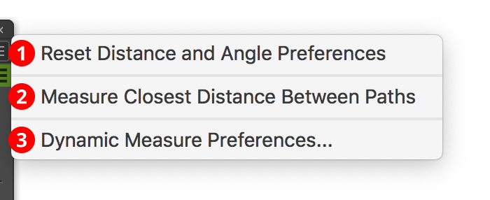
Dynamic Measure Flyout Menu
1. Reset Distance and Angle Preferences
Changes the Illustrator general preferences “Keyboard Increment” and “Constrain Angle” to their default values (1.0 pt and 0°).
2. Measure Closest Distance Between Paths
Available when exactly two paths are selected. Draws a measure that goes from the path which is higher in the stacking order to the other path and has minimal distance.
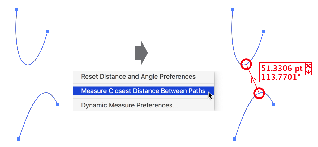
Dynamic Corners Flyout Measure closest distance
3. Dynamic Measure Preferences...
Brings up the Preferences dialog (see Dynamic Measure Preferences).
Dynamic Measure Preferences
The Dynamic Measure preferences dialog can be brought up in three ways: by choosing Dynamic Measure Preferences... in the flyout menu of the panel; by double-clicking on the Dynamic Measure tool icon in the toolbar; or by pressing the Return/Enter key when the Dynamic Measure tool is selected.
The preference dialog has four sections (General, Highlighting, On-Screen Display, and HoverMeasure) which can be accessed using the popup menu at top or the “Previous” and “Next” buttons at right.

Dynamic Measure Preferences (General)
1. Mode Setting
The default, two-click mode, is more powerful because you can zoom or scroll the document or even change these preference settings while in the middle of a measure.
2. Precision
Specifies how many digits with which to display values.
3. Measure Color Setting
Specifies the color in which Dynamic Measure’s line annotation is drawn (red or black).
4. Show Measure Direction Indicator
When enabled (the default), a small arrowhead in the the center of the measure indicates the direction in which the measure was made.
5. Copy Angle to Constrain Angle Preference
6. Always / Use Option/Alt Key Rotation
When enabled, the measured angle is copied to the Illustrator general “Constrain Angle” preference upon completion of the measure. A small angle icon appears next to the cursor to indicate that this copying will take place. You can have this option always enabled, or use the Option/Alt key to toggle it on and off.
7. Copy Distance to Keyboard Increment Preference
8. Always / Use Option/Alt Key Rotation
When enabled, the measured distance is copied to the Illustrator general “Keyboard Increment” preference upon completion of the measure. A small ruler icon appears next to the cursor to indicate that this copying will take place. You can have this option always enabled, or use the Option/Alt key to toggle it on and off.
9. Require Shift with Option/Alt for Angle/Distance Rotation
Because the Option/Alt key is also used for other things – e.g. in the keystroke for temporarily selecting the zoom-out magnifying glass – you may want to enable this preference so that you must press Shift at the same time as Option/Alt to rotate through the settings. Note that if you do this while in the middle of a measure, the measure line may momentarily jump while it is being constrained.
When HoverMeasure is enabled and Show Curve Normals or Show Point Normals are enabled, the Shift key and Option/Alt keys are used to control its functions when hovering over a path. To rotate through the Copy... preferences in this case, temporarily move away from the path. Likewise, because deleting or moving a measure use Shift and Option/Alt, these keys will not rotate the Copy preferences while over measure data or a measure’s endpoint.
10. Reset Distance/Angle Prefs on Shift+Tool Selection
Allows resetting of the Constrain Angle and Keyboard Increment preferences to their default values (1
pt and 0°) by holding down Shift and selecting the Dynamic Measure tool from the tool panel. You don’t actually need to make a measurement after doing this. Note: The Dynamic Measure tool must not already selected.
11. Default Font
12. Font Size
Specifies the font and its size that are used by default when converting a Dynamic Measure to artwork. Once the first measure has been converted in a document, all converted measures use the “Dynamic Measure” Paragraph Style, which can be edited as usual.
13. Line Weight
Specifies the weight of the line that is created by default when converting a Dynamic Measure to artwork. Once the first measure has been converted in a document, all converted measures use the “Dynamic Measure” Graphic Style, which can be edited as usual.
14. No Hardwired Arrowheads
When enabled, arrowheads are not drawn on the ends of converted measures with additional lines. Instead, you can edit the “Dynamic Measure” Graphic Style to add arrowheads via the Stroke panel.
15. Layer Is Initially Unlocked
When enabled, the layer into which converted Dynamic Measures are placed is left unlocked so they may be immediately edited.
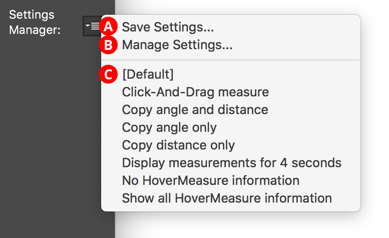
16. Settings Manager
Dynamic Corners Preferences setting manager menu option
The Settings Manager popup menu provides access to saving, managing, and applying preference settings.
A. Save Settings...
When you save the preference settings, all of the current settings in the preferences dialog are captured in a file which can be recalled later.
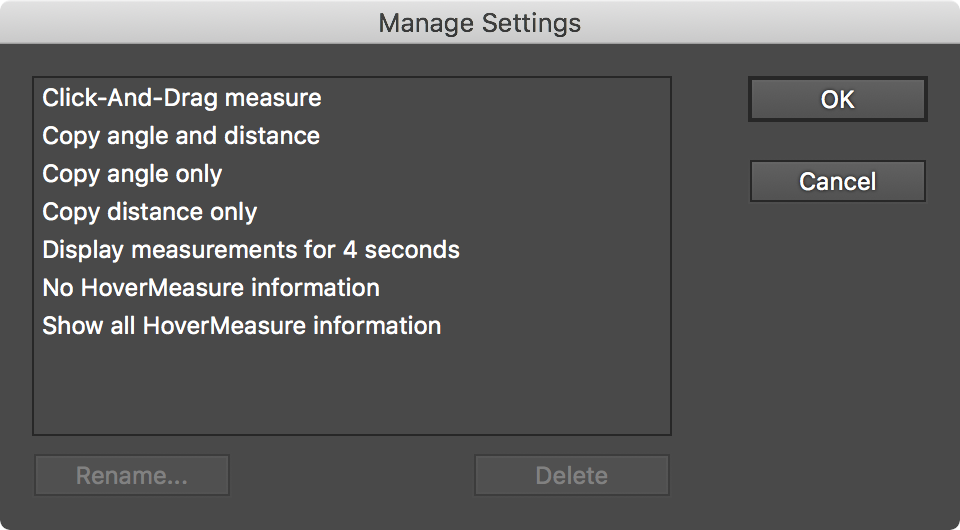
B. Manage Settings...
Brings up the Manage Settings dialog, which lets you rename or delete existing settings files:
Dynamic Corners Preferences manage settings
C. Settings List
Choosing a settings file from this list will change the preference settings to match the state of the panel when the settings file was saved (or, the case of “[Default]”, to the default values). Dynamic Measure comes with several simple pre-made settings files.

Dynamic Measure Preferences (Highlighting)
17. Highlight Cursor When Snapping With Smart Guides
Displays the cursor highlighting ring when Smart Guides are enabled, for extra visibility and to indicate the snapping status of the start point after the cursor has been moved away.
18. Highlight Cursor And Snap Without Smart Guides
19. On Path Segments Too
Causes the cursor to snap to anchor points and handles (and display the snapping ring) when Smart Guides are disabled. When On Path Segments Too is enabled, snapping will also happen to path segments and guides.
20. Snapping Ring Style
Lets you choose between four different styles of snapping rings.
21. Show Path Direction Arrows
22. Keep Arrows After Measure Only When Distance Along Path was Measured
When enabled (the default), red path direction arrowheads appear next to the cursor when it is over an unlocked path, to show you in which direction the path winds. This is most useful when measuring distance along a path, because on a closed path there are two distances along the path: one With the path direction and one Against. If you’re showing dimensional measurements after a measure, any path direction arrows will remain too. However, you can choose to show them after the measure is complete only if a distance along path measurement was taken.

Dynamic Measure Preferences (On-Screen Display)
23. Show Dimensional Measurements in Document Window
Displays the measurements as annotations near the measure (as opposed to only in the Information panel).
24. Mode Selection
In Continuous mode, values are displayed while the measure is in progress, but not afterwards (thus measures are never retained). The default mode is Both, which displays value during and after the measure.
25. Keep last __ measures
Specifies the number of measures to retain (up to a maximum of 50). For example, if you enter 10, then the last ten measures will stay on the screen. If you then make an eleventh measure, it will replace the first (oldest) measure. You can keep up to the last 50 measures; the default value is 25.
26. Retention Time
Specifies how long the measurements will remain on the screen: indefinitely (the default), or between 1 and 99 seconds.
27. Show Measurements When Tool is Deselected
Controls whether the measurements remain visible on the screen when you deselect the Dynamic Measure tool. The default is to remain.
28. Style Selection
Allows you to specify the style of the measurement values. When a setting is changed, the preview area below will update to show the new style. When Use Delta Symbol is disabled, the a lowercase “d” is used instead.
29. Positioning
Endpoint puts the measurements above and to the right of the endpoint of the measure (which, during an active measure, is the same as the cursor position). If two measures end at the same spot, however, their data will overlap. You can therefore choose Centered to place the measurements at the center of the measure line (above or below, depending on the angle of the measure). The third option, Endpoint, then Centered (which is the default), places the measurements by the cursor during an active measure but moves them to the center of the measure line afterwards.
30. Positioning
Previews what a measure will look like with the chosen Style and Position settings.

Dynamic Measure Preferences (HoverMeasure)
31. Enable HoverMeasure
Enables or Disable all HoverMeasure items (see Dynamic Measure Tool: HoverMeasure).
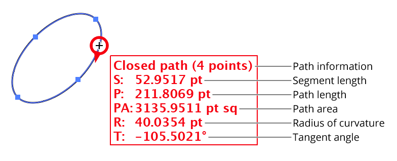
32. Show Path Information
Shows the type of path (open or closed) and the number of anchor points it contains.
33. Show Segment Length
34. Show Path Length
Shows the length (as measured along the curves of the path) of the segment (prefixed by “S:”) and the path (prefixed by “P:”).
35. Show Path Area
Shows the area of the path (prefixed by “PA:”). Open paths are treated as if there were a straight segment connecting the endpoints. Subpaths of compound paths are treated independently, so to measure the area of a donut, say, you must subtract the area of the inner path from the area of the outer path. Paths with self-intersections are not valid for measuring area; it may be possible to use the PathFinder Unite function to split it into multiple non-self-intersecting paths and measure their areas separately.
36. Show Radius of Curvature
Shows the radius of curvature at a spot along the path (prefixed by “R:”).
37. Show Tangent Angle
Shows the angle of a straight line tangent to the path at that spot (prefixed by “T:”).
Dynamic Measure example show tangent angle
38. Show Curve Normal(s) with Option-Alt/Shift
39. Divisions
When Option/Alt is pressed (Shift may be added), divides the bezier segment into the specified number of sections (from 2 to 1000) and draws a straight line normal (perpendicular) to the path at each spot, with a length equal to the radius of curvature. Lines are not drawn if the radius of curvature is infinite (such as on a straight line). See Dynamic Measure Tool: Curve Normals.
40. Show Point Type
Shows the type of anchor point (Corner or Smooth).
41. Show Point Number
Shows the index of the anchor point (which starts at zero and increases in the direction of the path), and the range of indices in the entire path.
42. Show Point Coordinates
Shows the X and Y coordinates of the anchor point.
43. Show Handle Information
Shows the length and angles of the handle(s) for the anchor point. “IH:” prefixes the In handle data, and “OH:” prefixes the Out handle data.
44. Show Radius/ii of Curvature
Shows the radius/ii of Curvature of the path as it passes through the anchor point, prefixed with “R:”. If the radii are different between the segment on the in side of the point and the segment on the out side (such as with corner points), then both values are shown, with “(in)” and “(out)” appended to distinguish them.
45. Show Tangent Angle(s)
Shows the angle of a straight line that is tangent to the path as it passes through the anchor point, prefixed with “T:”. If the angles are different between the segment on the in side of the point and the segment on the out side (such as with corner points), then both values are shown, with “(in)” and “(out)” appended to distinguish them.
46. Show Path Angle at Point
Shows the angle between the segment as it enters the anchor point and the segment as it leaves the anchor point. It is indicated by “A:” and is not displayed for endpoints. The corner points of a rectangle, for example, will all have path angles of 90°. Smooth points will always have an angles of 180°.
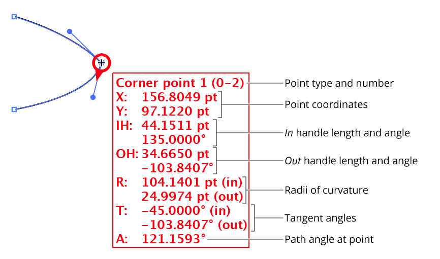
Dynamic Measure point information
47. Show Point Normal(s) with Option-Alt/Shift
Similar to its counterpart Show Curve Normal(s), except that both Option/Alt and Shift do the same thing.
48. Show Handle Coordinates
Shows the X and Y coordinates of the handle.
49. Show Handle Length
Shows length of the handle.
50. Show Handle Angle
Shows angle of the handle.
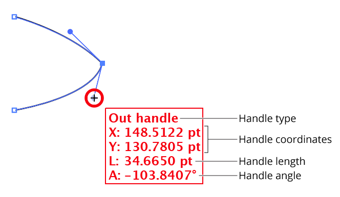
Dynamic Measure Show Handle Information
51. Help Button
Opens the help documentation in the Astute Manager. If this does not automatically appear, please ensure your Astute Manager is running first.