Editing Paths
 InkScribe
![]() InkScribe Tool
InkScribe Tool
![]() Reform Panel
Reform Panel
![]() PathScribe Tool
PathScribe Tool
![]() AG Trim and Join Tool
AG Trim and Join Tool
![]() Reprofile Panel
Reprofile Panel
 Orient Transform Tool
 Extend Path Tool
Path Intersections
 AG Utilities Live Effects
 QuickOps Panel
Illustrator Location:
Advanced Toolbar > Pen Stack > InkScribe Tool
The InkScribe tool appears in Illustrator’s main toolbar (which must be in Advanced mode: View > Toolbars > Advanced), stacked under the native Pen tool. As with other stacked tools, click and hold on the top tool icon to display the tools stacked under it.
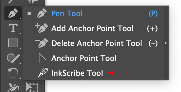
InkScribe Tool Location
The InkScribe tool’s primary cursor looks like the end of a technical pen, and can have badges and additional forms:
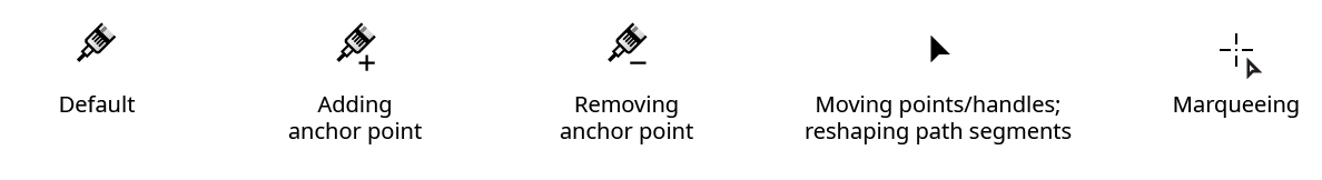
InkScribe Tool Cursors
Illustrator Location:
As the InkScribe tool has several keypresses which can add or change its functionality, we suggest installing the free Astute Graphics plugin Astute Buddy, which creates a panel that dynamically updates to inform you of the various keys which can be pressed in the tool’s current context.
The InkScribe tool is works in conjunction with the associated InkScribe panel, which should be open and accessible. If you are using the free Astute Graphics plugin DirectPrefs, you can have the InkScribe panel automatically be shown when the InkScribe tool is selected.
At its most basic, the InkScribe tool is a direct replacement for the native Pen tool. By default, clicking creates an anchor point with no handles, while clicking and dragging creates an anchor point with two handles. If nothing was originally selected and the tool was clicked away from any existing paths, a new path will be started. If a path was already in the process of being drawn, then it will be continued, adding another point to it. By default, a “rubber band” annotation shows a preview of the new path segment before the mouse button is clicked.
Although the InkScribe settings can be changed to make it quite similar in feel to the native Pen tool, with its default settings there are several differences. First, a small annotated “virtual panel” is drawn after the anchor point is created (nearby, “attached” to the point with a leader line, and with virtual buttons similar to those on the InkScribe panel), which allows common actions such as changing the anchor point between corner and smooth type as well as specifying the properties for the next-drawn path segment and point. Second, when the InkScribe cursor is hovered over an anchor point or handle, it changes to an arrowhead to indicate that the point/handle can be moved by simply dragging it; a ring indicates that the cursor is snapping to that point/handle; and the type of point (corner or smooth) is also displayed.
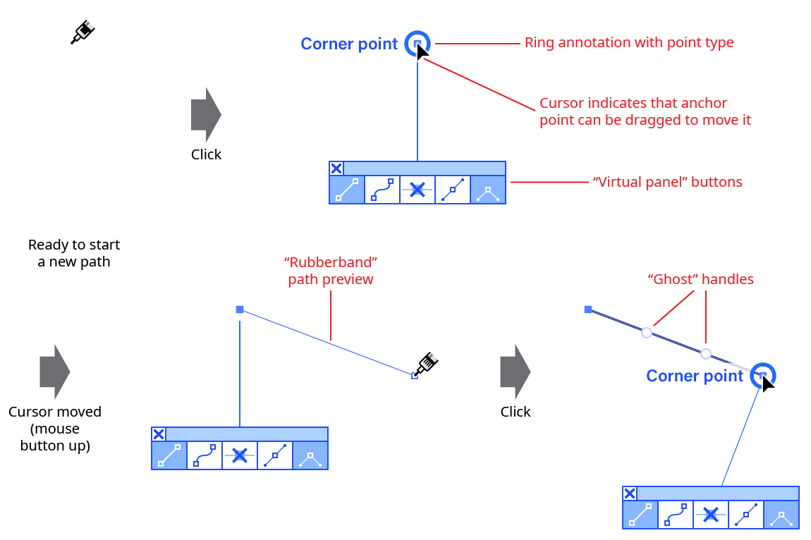
InkScribe New Path Example
If a segment was created that does not have two handles, “ghost” handles (virtual handles which may be dragged to create real handles for the segment) are annotated along the path:
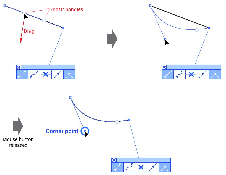
InkScribe Ghost Handle Example
Unless the tool preference Click-Drag Segments to Reshape is disabled, the InkScribe tool can also directly reshape the segments of selected paths by clicking-and-dragging on them.
Illustrator Location:
When reshaping an entire closed path, delimiters are not necessarily helpful, because, in a sense, the path does not have a beginning and an end. In this case you may use Looped mode. In this mode, which is only applicable for closed paths, there are no delimiters. Instead, there is a special blue marker pair which is located at “point zero” along the path and cannot be moved or deleted. If point zero is smooth, the pair will appear as a single marker; if point zero is a corner point, the markers will appear separately. In either case, the pair's common length may be adjusted by dragging either of the blue markers to set the offset of the path at that point. Additional normal markers may be set at other positions along the path.
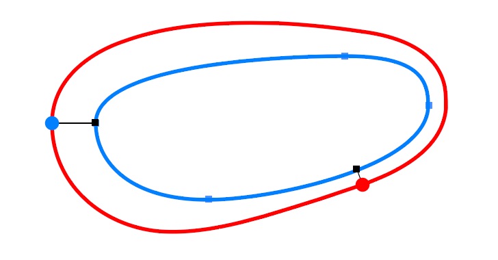
Reform Looped Mode
To enter looped mode on a closed path which is already being reshaped, doubleclick either one of the delimiters. To enter looped mode immediately when starting a new reshape, hold down Option/Alt when initially clicking or dragging the path.
Since the entire path is affected in looped mode, the Transition parameter is no longer applicable.
Illustrator Location:
A common operation is to extend one section of a path by a uniform amount. You can achieve this by placing markers of equal offset value exactly on the start and end delimiters. To save time, you may quickly create a constant offset by holding down Shift-Option (Mac) or Shift-Alt (Windows) while initially dragging the path to create a new reshape:
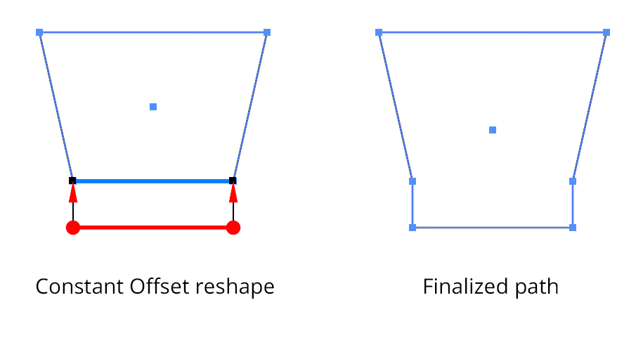
Reform Constant Offset Profiles
Illustrator Location:
Clicking
Clicking on a path segment without any modifier keys selects it, causing its handles (in handle at one end, out handle at the other end) to become visible (if they exist), and hiding other handles on the same path. Other paths are not affected: if they were fully- or partially-selected, they remain so. Marqueeing over a segment acts in the same way as clicking on it.
If the Show All Handles on Selected Paths preference is enabled, clicking on a path segment selects all of the segments on the path (thus causing their handles to become visible).
Adding one more modifier keys while clicking a path segment changes or adds functionality:
Shift: As with a point,
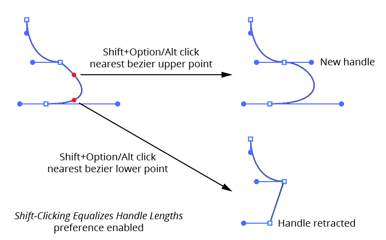
Shift-clickingon a path segment will, by default, simply add or remove the path segment from the selection (unless the Show All Handles on Selected Paths preference is enabled, in which caseShift-clickingdoes nothing). However, by enabling the preference Shift-Clicking Equalizes Handle Lengths, it instead equalizes the path segment’s handle lengths (handle angles are not affected). How the length is calculated depends on where you click along the length of the segment.Shift-clickingin the middle third will average the handle’s lengths together, whileShift-clickingin either of the outer thirds will change the length of the nearest handle to match the opposite one:

PathScribe Shift-clicking on path will add or remove segment from selection
Option/Alt: By default,
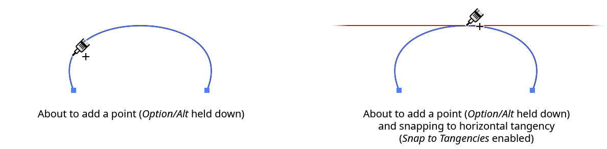
Option/Alt-clickingon a path segment will add a new smooth point to the path at the clicked point. The cursor shows a “plus” sign. If the preference Snap to Tangencies is enabled, the cursor will snap to vertical, horizontal and diagonal tangencies on the path segment (the constrain angle is honored). A red guide will appear when the cursor is snapping to show you the tangent direction:

PathScribe path add point
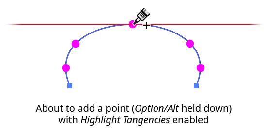
Additionally, you can choose to highlight all of the tangencies on the current path segment with a small magenta dot by enabling the Highlight Tangencies preference:
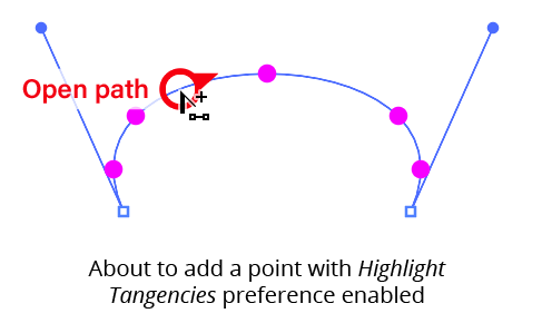
PathScribe add point highlight tangencies on the current path
If the Option/Alt-Clicking Adds New Point to Path preference is disabled, then Option/Alt-clicking a path selects all of the path’s segments, thereby making all of the handles on the entire path visible. You can do this even while in Multi-Handle Mode. Other paths are not affected.
Shift+Option/Alt: By default,
Shift+Option/Alt-clickingon a path segment toggles the visibility state of all the handles on the entire path. If a path has only some of its handles visible,Shift+Option/Alt-clickingon the path will hide them. However, by enabling the preference Shift-Clicking Equalizes Handle Lengths, it instead will retract or extend new handles. If the handle nearest the click exists, both handles will be retracted; otherwise, new handles are created where they don’t already exist. In both cases, adjacent path segments are not affected.
PathScribe Shift+Option-clicking on path toggles visibility state
Dragging
Dragging a path segment reshapes it, similarly to the Direct Selection tool. The closer the initial mouse-down is to one point, the more that point’s handle movement is affected by the cursor movement and the less the other handle is affected. Starting the drag midway along the path between the points affects both handles equally. If the Keep Path Under Cursor When Dragging preference is disabled, handles are still moved relative to the initial click location, but the path will not necessarily pass through the cursor position.
If either of the segment’s handles does not exist at the start of the drag, new ones will be created. Their initial location is controlled by PathScribe’s Smoothing Ratio preference.
Normally, adjacent segments will also be affected when you drag a segment if its endpoints are smooth points, since the opposing handles must change angles to remain 180° away from the moved handles. If you’d rather only affect the dragged segment in isolation, you can enable the preference Convert Smooth Points to Corner Points When Dragging Path Segments:
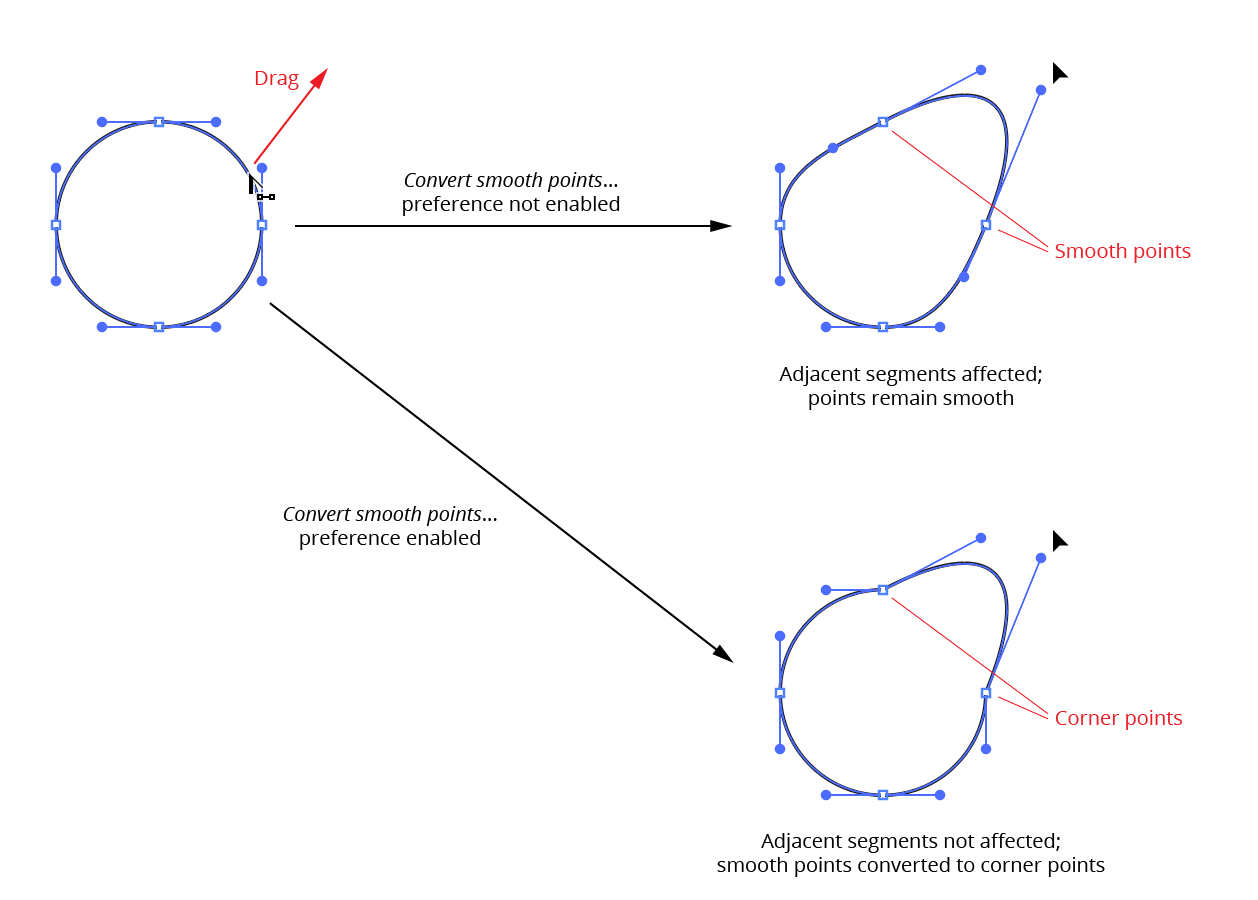
PathScribe Path drag break
This preference can also be changed on the fly by pressing the D key.
Note: When you are using Recognize Connector Points, segments with connector points at one or both ends are affected differently by drags, since a connector point can have only one handle at a fixed angle; see Connector Points).
While dragging, there are various keys which can be pressed to perform additional functions:
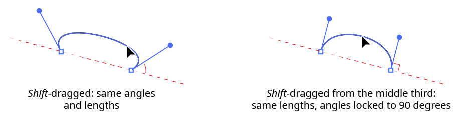
Shift: Reshapes the path segment while keeping it symmetric. Symmetric means that both handles are of the same length and are at the same angle to the imaginary line running through the endpoints of the path segment.
Shift-draggingfrom the middle third of a path segment will additionally constrain the handle angle to be perpendicular to this imaginary line:
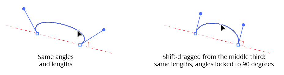
PathScribe path drag symmetrical handles
Except for middle-third Shift-dragging, if you release the Shift key (or if you started dragging without it) and later hold it down, the curve will become symmetric using the lengths and angles of the handles as they exist at that moment.
Option/Alt: Constrains the angles of the handles to their original values (±180°). If you have the Option/ Alt-Clicking Adds New Point to Path preference enabled, you must hold down
Option/Altafter you hold down the mouse button, or you will inadvertently add a point to the path. But even if you begin to drag withoutOption/Alt, holding it down afterwards will reset the angles of the handles to the angles they had when you originally moused down on the path. Note: If the initial mouse-down was close to one of the ends of the segment, the segment shape will probably be very sensitive to movement of the cursor. You can gain better control of the final segment shape by using slow-drag in this situation.Shift+Option/Alt:
Shift+Option/Alt-dragginga path segment reshapes it with the following constraints: the handle lengths are kept equalized, and the handle angles are constrained to their original values. As withOption/Alt-dragging, handle angles will be set to the original angles unlessShiftwas held down by itself first (which will have made the curve symmetric). This allows you to first symmetrize a curve until the handles are at the angle you like, and then lengthen or shorten them without losing the symmetry. WhenShiftandOption/Altare both held down before you drag, neither the Shift-clicking Equalizes Handle Lengths nor the Option/Alt-Clicking Adds New Point to Path preferences apply.D: Toggles the current Convert Smooth Points to Corner Points When Dragging Path Segments preference. The preference reverts to its original value when the mouse button is released.
R: Retracts the handles of the path segment being dragged.
S: Immediately converts the path segments endpoints to smooth type points.
T: Enables “Tangent constraining.” In this mode, the angle of the path segment as it passes through the cursor position is kept constant, regardless of where the cursor is dragged. To achieve this, the segment’s handles are adjusted in a different manner from a normal drag.
Illustrator Location:
Advanced Toolbar > Pen Stack > InkScribe Tool
When a path is at least partly-selected, its segments may be edited in several ways:
Clicking a path segment does nothing unless the tool preference Click-Drag Segments to Reshape has been disabled (in that case, clicking adds an anchor point to the path segment at the clicked location).
Option/Alt-clicking will add an anchor point to the path segment, as long as the tool preference Option/Alt-Clicking Inserts New Point in Path has not been disabled. The cursor shows a “+” sign when an anchor point will be added. If the sub-preference Snap to Tangencies is enabled, the cursor will snap to vertical, horizontal and diagonal tangencies on the path segment (taking into account the general constrain angle). A red guide will appear when the cursor is snapping, indicating the tangent direction:
InkScribe Add Point Example
Additionally, you can choose to highlight all of the tangencies on the current path segment with a small magenta dot by enabling the Highlight Tangencies sub-preference:
InkScribe Add Point Highlight Tangencies
Dragging a path segment reshapes it, similarly to the Direct Selection tool (unless the tool preference Click-Drag Segments to Reshape is disabled). The closer the initial mouse-down is to one anchor point, the more that point’s handle movement is affected by the cursor movement and the less the other handle is affected. Starting the drag midway along the path between the points affects both handles equally. If the Keep Path Under Cursor When Dragging sub-preference is disabled, handles are still moved relative to the initial click location, but the path will not necessarily pass through the cursor position. If either of the segment’s handles does not exist at the start of the drag, new ones will be created. Adjacent segments will also be affected when you drag a segment if its endpoints are smooth points, since the opposing handles must change angles to remain 180° away from the moved handles.
Note: When you are using Recognize Connector Points, segments with connector points at one or both ends are affected differently by drags, since a connector point can have only one handle at a fixed angle; see Connector Points.
While dragging a segment, there are various keys which can be pressed to perform additional functions:
Shift: Reshapes the path segment while keeping it symmetric. Symmetric means that both handles are of the same length and are at the same angle to the imaginary line running through the endpoints of the path segment.
Shift-draggingfrom the middle third of a path segment will additionally constrain the handle angle to be perpendicular to this imaginary line:
InkScribe Path Drag Symmetrical Handles
Except for middle-third Shift-dragging, if you release the Shift key (or if you started dragging without it) and later hold it down, the curve will become symmetric using the lengths and angles of the handles as they exist at that moment.
Option/Alt: Constrains the angles of the handles to their original values (±180°). If you have the Option/ Alt-Clicking Inserts New Point in Path preference enabled, you must press the key after you hold down the mouse button, or you will inadvertently add a point to the path. But even if you begin to drag without
Option/Alt, holding it down afterwards will reset the angles of the handles to the angles they had when you originally moused down on the path. Note: If the initial mouse-down was close to one of the ends of the segment, the segment shape will probably be very sensitive to movement of the cursor.Shift+Option/Alt:
Shift+Option/Alt-dragginga path segment reshapes it with the following constraints: the handle lengths are kept equalized, and the handle angles are constrained to their original values. As withOption/Alt-dragging, handle angles will be set to the original angles unlessShiftwas held down by itself first (which will have made the curve symmetric). This allows you to first symmetrize a curve until the handles are at the angle you like, and then lengthen or shorten them without losing the symmetry.R: Retracts the handles of the path segment being dragged, making it straight.
Illustrator Location:
In the example of the Constant Offset reshape, it is natural to want the offset path section to extend from the original path at its original angle. This is where “Smart Joining” provides a solution. With Smart Joining enabled (by clicking the button on the panel), Reform will, when possible, try and extend the path section while keeping the path's original angle:
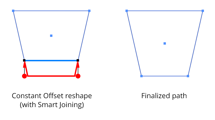
Reform Smart Join Option
When dragging out a constant offset, you can toggle Smart Joining by pressing the S key. The Smart Joined extension is always straight, even if the path is curved.
Illustrator Location:
As the AG Trim and Join tool has several keypresses which can add or change its functionality, we suggest installing the free Astute Graphics plugin Astute Buddy, which creates a panel that dynamically updates to inform you of the various keys which can be pressed in the tool’s current context.
Much of the functionality of the AG Trim and Join tool is also available in the Dynamic Sketch tool. However, that tool requires the Shift modifier key to be pressed to enable trimming, and does not offer style-dependent joining.
To use the AG Trim and Join tool, simply drag it across a path, over the part that you want removed. A dashed line (blue by default) will show you the path of the tool. Cuts are made at the nearest intersection with another path, not at the position where the tool was dragged over the path:
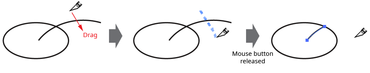
AG Trim and Join Tool Trimming Example
Multiple paths may be trimmed in one pass:
AG Trim and Join Tool Trimming Multiple Paths Example
For closed paths to be trimmed, they must be intersected in at least two positions by another path (or must self-intersect). However, only one section of a closed path can be trimmed at a time:
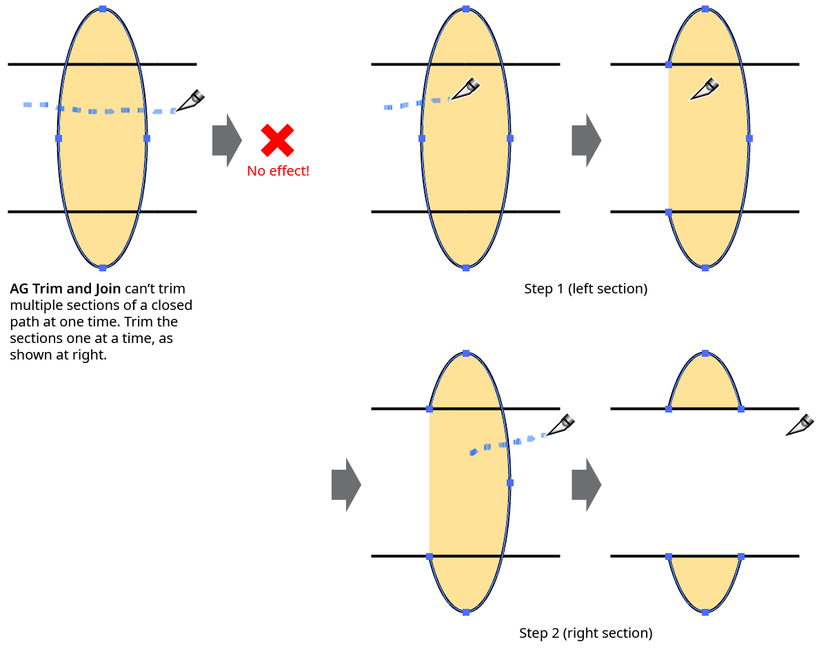
AG Trim and Join Tool Trimming Closed Path Example
The path(s) to be trimmed need not be selected. However, if the preference Prefer Selected Paths is enabled, then when the tool is dragged across a mix of both selected and unselected paths, only the selected paths will be trimmed.
When a path with a variable width stroke is trimmed, by default AG Trim and Join attempts to retain the width profile(s) of the untrimmed section(s) as they existed prior to the trimming. This behavior may be adjusted using the tool preference Trimming Splits Profiles.
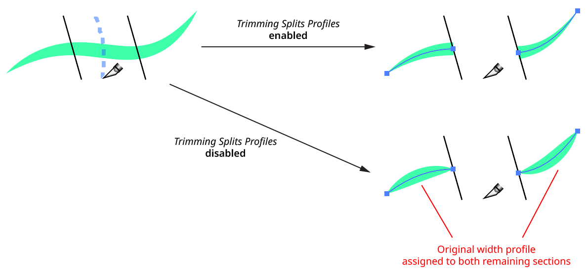
AG Trim and Join - Variable Width Stroke
If the tool preference Auto-Join Paths After Trimming is enabled, trimmed paths which contain an endpoint which is at the same spot as another path endpoint will be joined to that path (unless sub-preferences are set which only allow joining under certain circumstances; see AG Trim and Join: Preferences).
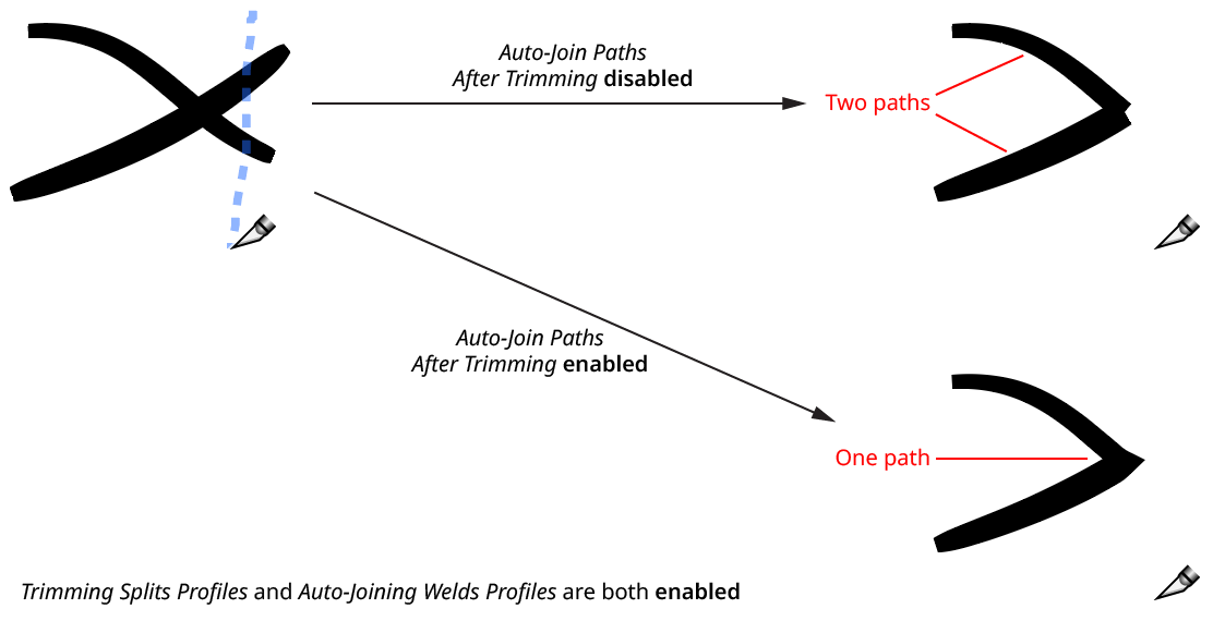
AG Trim and Join Tool - Auto-Join Paths Example
When paths with variable stroke widths are auto-joined, by default the stroke width profiles of each section will be preserved as best as possible, by “welding” together the profiles of each half. Note that this is in contrast to joining the paths with the native Command/Ctrl-J, which instead takes the entire stroke width profile for the joined path from the topmost of the original paths. However, the native behavior can be emulated using the tool preference Joining Welds Profiles.
Keypresses
While dragging the tool to trim a path, several keys may be pressed to held down for additional options:
Esc: Aborts the current trim operation (nothing will happen when the mouse button is released).
Option/Alt: Starts a “rubberband” section – a completely straight section that stretches between the point at which the modifier key was held down and the point at which it is released.
Shift: When creating a rubberband section, constrains the rubberband to angles that are 45° increments around the general constrain angle.
C: Changes the annotation color (for the dashed line preview) among the following choices: blue (default), red, magenta, green, cyan, and black.
D: Forces variable width profiles not to be split for the current operation, even when the preference is set to split them.
J: Forces joining of paths for the current operation, even when the preference is set to not join.
N: Forces no joining of paths for the current operation, even when the preference is set to join.
S: Forces variable width profiles to be split for the current operation, even when the preference is set to not split them.
Illustrator Location:
Reform has an internal Undo/Redo system that keeps track of all changes as you refine the profile. If you move a marker, for example, but then want to put it back exactly where it was, you can simply undo your last change. Reform uses the keystrokes that Illustrator assigns to the tool commands “Decrease/Increase Diameter” to do this. By default, these are the left and right square bracket keys respectively ( [ and ] ), but these may be reassigned, as with any keyboard shortcut.
Resetting or applying a Reform profile clears the Undo/Redo history.
Illustrator Location:
Illustrator Main Menu > Window > Astute Graphics > Reform > Panel Flyout Menu > Save/Manage Width Profiles...
"Profiles" (sequences of offset markers along a delimited extent) may be saved and recalled, so that multiple paths may be reshaped in the same manner. To save a profile, use the panel flyout menu when a reform operation is in progress and choose Save Profile... and give the profile a name. To apply an existing profile to a path, start editing the path with the Reform tool and (if necessary) move the delimiters to the desired positions. Then choose the desired profile from the panel flyout menu.
Note that parameters such as transition and clipping are not saved with the profile.
Profiles may be renamed or deleted by choosing Manage Profiles... from the panel flyout menu.
Illustrator Location:
Illustrator Main Menu > Window > Astute Graphics > InkScribe
The menu item to show and hide the InkScribe panel can be found in the main menu under Window > Astute Graphics > InkScribe. The InkScribe panel contains the same ten point and path buttons that can appear on the virtual panel. It also allows control over various options that affect the InkScribe tool, such as whether connector recognition is on or off, or whether paths can be joined together.
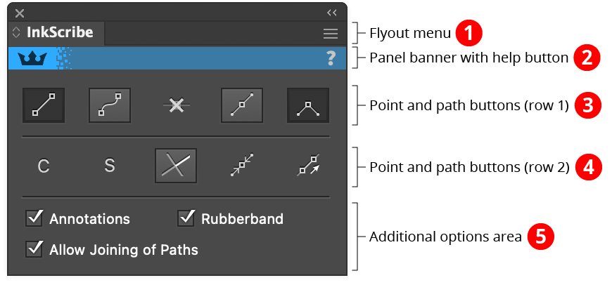
InkScribe Panel
1. Flyout menu
See InkScribe Panel: Flyout Menu.
2. Panel banner
The InkScribe panel banner has a help button on the right which opens the help documentation in the Astute Manager. If this does not automatically appear, please ensure your Astute Manager is running first.
3. Point and Path Buttons (row 1)
a. Straight Segment Button: When continuing a path, and the cursor is clicked (without dragging) to create a new anchor point, if the straight segment button is in its enabled state (shaded), then the segment created will be straight, with no handles (any Out handle on the previous anchor point will automatically be removed).
b. Curved Segment Button: When continuing a path, and the cursor is clicked (without dragging) to create a new anchor point, if the curved segment button is in its enabled state (shaded), then the segment created will be curved, with a new Out handle automatically added to the previous anchor point. The exception is when the previous segment was straight, and the tool preference Continuing From Straight to Curve is set to Keep Handle Retracted, in which case the segment remains straight.
c. Smart Remove Point Button: Removes the selected anchor point(s) and adjusts the handles of the points on either side of the removed point(s) so the resulting path shape is as close to the original as possible (see example in InkScribe Tool: Existing Point Operations). To remove one or more anchor points without adjusting handles, hold down Option/Alt when clicking the button.
d. Smooth Point Button: Changes all selected anchor points to smooth points. By default, this also adds new handles to these points so they all have two opposed handles. This is useful for creating a path that runs smoothly through the points:
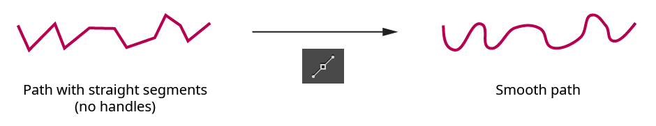
InkScribe Panel - Smoothing Example
The algorithm that InkScribe uses to create new handles is as follows: If a point already has one handle, its second handle is created by mirroring the existing handle. If a point has no handles, the new handle angle is calculated by bisecting the angle formed by the previous point, the point in question, and the next point, and taking its perpendicular. The new handle length is calculated by taking the lesser of the distances from the point in question to the previous and next points, and multiplying by 0.3905. This ratio causes a square to be turned into a circle when its points are smoothed. Handles of endpoints of open paths, if created, are adjusted to aim towards the next/previous handle.
e. Corner Point Button: Changes all selected anchor points to corner points. No handles are created or changed.
4. Point and Path Buttons (row 2)
a. Connector Point Recognition Button: Enables or disables Connector Point recognition. When the “C” symbol is dim, connector point recognition is off and the InkScribe tool will not afford any special handling to points which qualify as connectors. See InkScribe Tool: Connector Points.
b. Smart Smooth Button: Enables or disables “Smart Smooth”, a feature of the InkScribe tool which allows you to convert a corner point into a smooth point simply by dragging one of the point’s handles to be opposite the other (within a certain tolerance). A small red “S” annotation is drawn over points which are being aligned this way. The threshold angle value can be specified in the Preferences dialog.
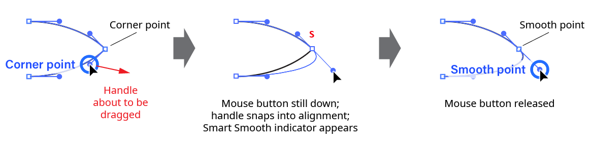
InkScribe Panel - Smart Smooth
c. Constrain Angle Button: When this button is in its enabled state (shaded), new points can only
be created at 45° angle increments from the previous point (honoring the constrain angle). Existing points that are moved can only be moved along these same angles. New handles and handles which are edited must also have these same angles.
d. Retract Handles Button: Retracts all of the handles on the selected anchor point(s). Point types are not changed. Holding down Option/Alt while clicking the button activates an alternate function: it swaps the positions of the In and Out handles on each selected point.
e. Close/Join Paths Button: Closes one or more open paths that are at least partially-selected, honoring any out-facing handles which may exist on the path’s endpoints. But if the selection consists of exactly two endpoints on two open paths, then the two paths are instead joined together.
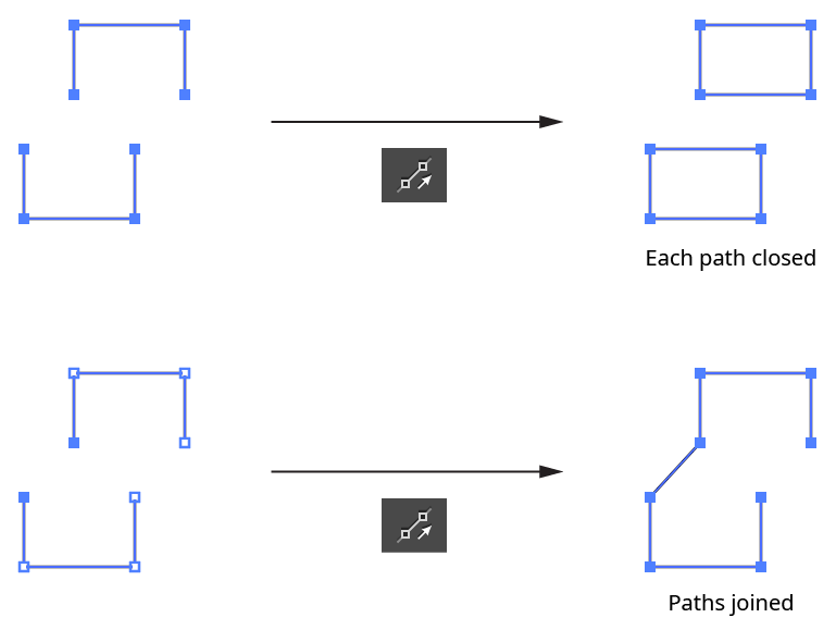
InkScribe - Close Join Path Example
5. Additional Options Area
a. Annotations: Enables or disables the virtual panel annotation which appears when a single anchor point is selected.
b. Rubberband: Enables or disables the “rubberband” preview of the segment about to be drawn.
c. Allow Joining of Paths: When disabled, continuing one path onto the endpoint of another path will not automatically join the first path to the second (however, open paths can still be closed).
Illustrator Location:
When reprofiling an entire closed path, the target path does not have a beginning and an end. In this case you may use “looped mode”. In this mode, which is only applicable for closed paths, there are no delimiters. Instead, there is a special blue marker pair which is located at “point zero” along the path and cannot be moved or deleted. If point zero is smooth, the pair will appear as a single marker; if point zero is a corner point, the markers will appear separately. In either case, the pair's common length may be adjusted by dragging either of the blue markers to set the height of the path at that point. Additional normal markers may be set at other positions along the path.
Reprofile Terminology Looped Mode
To enter looped mode on a closed path which is already being reshaped, doubleclick either one of the delimiters. To enter looped mode immediately when starting a new reshape, hold down Option/Alt when initially clicking or dragging the path.
Since the entire path is affected in looped mode, the Transition parameter is no longer applicable.
Illustrator Location:
A common operation is to extend one section of a path by a uniform amount. You can achieve this by placing markers of equal height value exactly on the start and end delimiters. To save time, you may quickly create a constant offset by holding down Shift + Option/Alt while initially dragging the path to create a new reprofile.
Illustrator Location:
Illustrator Main Menu > Window > Astute Graphics > Reprofile > Panel Flyout Menu > Save/Manage Width Profiles...
Reprofile shares width profile settings with Reform. Reprofile width profile settings can be used in Reform, or Reform profiles in Reprofile. A Reprofile operation consists of a Reform operation to set the guide paths followed by a second operation to apply the Reprofile profiles. To avoid confusion, in Reprofile, Reform profiles are termed “width profiles”. Reform profiles (sequences of offset markers along a delimited extent) may be saved and recalled, so that multiple paths may be reshaped in the same manner. To save width profile settings, use the panel flyout menu when a Reprofile operation is in progress and choose Save Width Profile... and give the settings a name. To apply an existing Reform profile or Reprofile Width Profile setting to a path, start editing the path with the Reprofile tool and (if necessary) move the delimiters to the desired positions. Then choose the desired width profile setting from the panel's flyout menu.
Width profile settings may be renamed or deleted by choosing Manage Width Profiles... from the panel flyout menu.
Illustrator Location:
Advanced Toolbar > Orient Stack > Orient Transform Tool
As the Orient Transform tool has several keypresses which can add or change its functionality, we suggest installing the free Astute Graphics plugin Astute Buddy, which creates a panel that dynamically updates to inform you of the various keys which can be pressed in the tool’s current context.
To use the Orient Transform tool, two reference lines must be drawn: a source line and a destination line. This can be done by using one of two methods: by clicking once on each endpoint, or by clicking and dragging. The former method has the advantage of allowing you to scroll, zoom, change the view mode, etc. in the middle of the operation. However, to use several shortcut keypresses (detailed below), you must continue to hold the mouse button down after the second click used to define the second reference line.
Reference lines are annotated with small circles (red, by default) at each end; the source line is solid while the destination line is dotted. The cursor will snap to anchor points, raster image corners, and the ends of point text baselines even when Smart Guides are turned off.
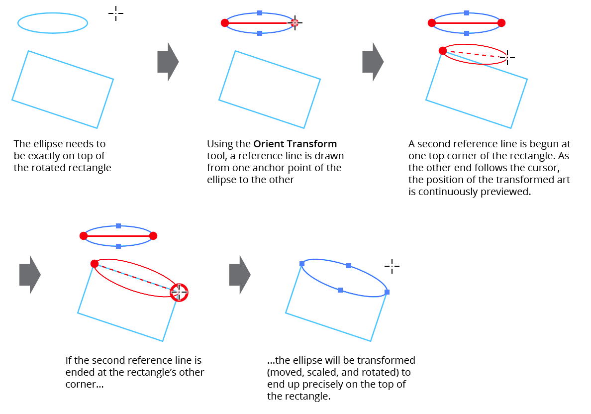
Orient Transform Tool Example
While the destination reference line is being drawn, all selected art objects will be previewed in red in the new position and size they would have after being linearly transformed such that the source reference line would be mapped onto the destination reference line. Releasing the mouse button after drawing the destination reference line finalizes the transformation. If Option/Alt is held down, the art is duplicated to its new position rather than being moved. Holding down the Shift key constrains either reference line to 45° increments around the general constrain angle.
If the destination reference line is being drawn by dragging, or if the mouse button is held down after the second click, several additional keypresses may be used to add or change functionality. As with all Astute tool keypresses, these will be indicated on the Astute Buddy panel.
Space: Flips the orientation of the transformed art, as if the destination reference line had been drawn in the opposite direction. This is faster than actually redrawing the line.
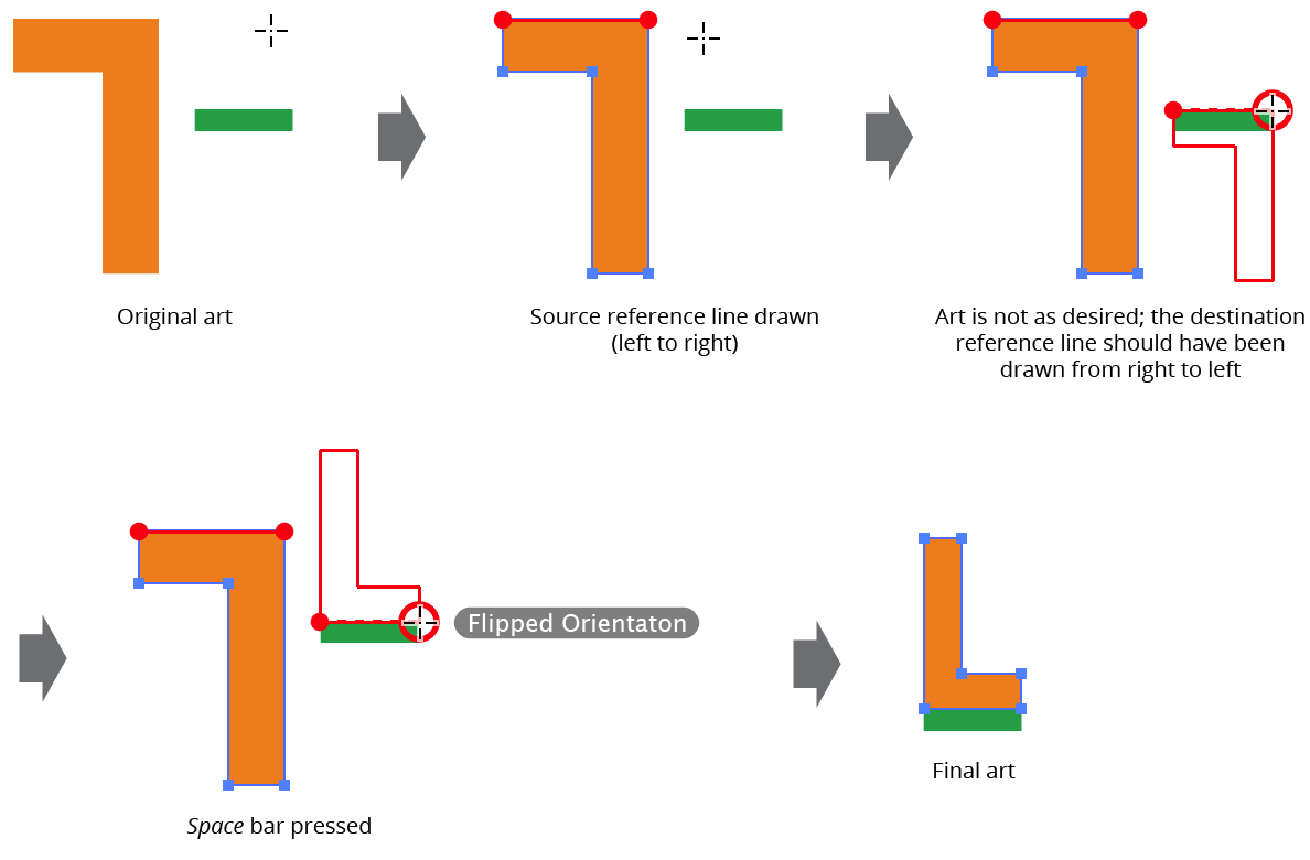
Orient Transform Flipped Orientation
A: Toggles mirroring. When mirroring is enabled, after being transformed, the artwork is additionally reflected across the destination reference line, which is drawn with a more widely-spaced dotted line.
Mirroring mode is retained across uses of the tool.
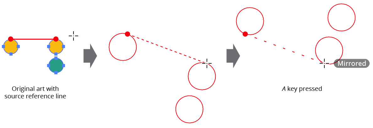
Orient Transform Mirrored Orientation
D: Toggles persistent duplicate, so the
Option/Altkey does not need to be held down to duplicate art. This can be useful when using the tool to make many successive copies of an art object. The mode is retained across uses of the tool.R: Toggles “retain selection” mode. Normally, after duplication, the selection is switched to the new transformed duplicate (and the source reference line is moved to the position of the destination reference line). However, when retain selection mode is enabled, the original art remains selected and the source reference line remains in its original position. Retain selection mode is always disabled to start.
S: Toggles size locking mode. When the size is locked, only the position and angle of the selected artwork will be modified.
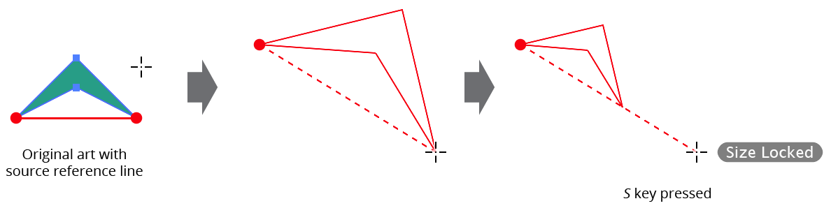
Orient Transform Size Locking
The Orient Transform tool honors the general preference Scale Stroke & Effects.
Illustrator Location:
Advanced Toolbar > PathScribe Stack > Extend Path Tool
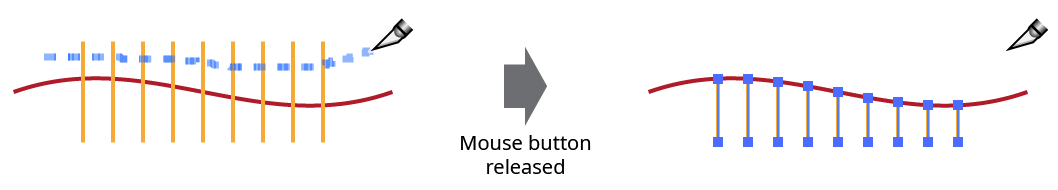
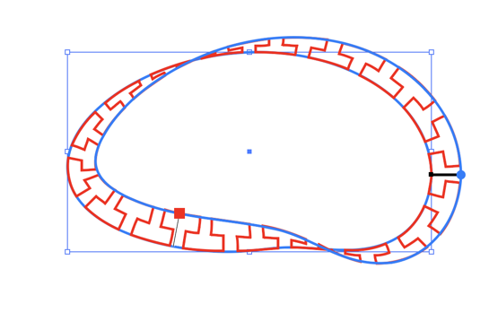
When the Extend All Selected Open Paths preference is enabled, all selected open paths will be simultaneously lengthened or shortened, in addition to the path under the cursor. Unless randomization is being used, the amount of lengthening or shortening is the same as the dragged path. When randomization has been enabled with the Q key, the values for additional paths are randomly changed by an amount up to the maximum random variation value, which can be changed using the O and P keys while dragging.
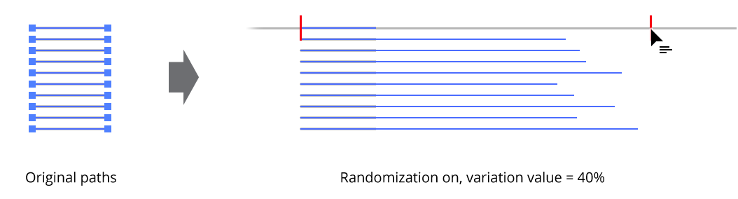
Extend multiple paths randomly
Illustrator Location:
Illustrator Main Menu > Object > Path > Path Intersections...
VectorScribe adds a submenu item to the main Illustrator Object > Path menu: “Path Intersections...
It allows you to add anchor points to (or cut) the positions along all selected paths where the path intersects itself or another path. This is especially useful when working on stroked but unfilled paths, since only a few of the native PathFinder operations work with them, and those that do (such as “Outline”) strip the paths of their appearance.
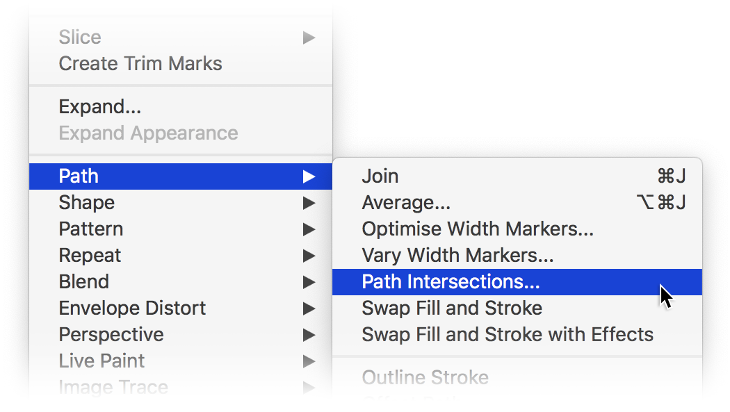
Path Intersections Menu Item
Choosing the menu item (which may be assigned a keyboard shortcut) brings up a dialog:

Path Intersections Dialog
1. Add Points to Paths
2. Cut Paths
Chooses the operation to make at all eligible points of path intersection.
3. Only Consider Intersections With Top Path
Intersections between paths which are not the top path will be ignored.
4. Ignore Self-Intersections
Points at which a path intersects with itself (e.g., a loop) will be ignored.
5. Don’t Alter Topmost Path
It is often useful to create a temporary path over your art to act as a “cookie-cutter” for the paths below it. By leaving this topmost path intact, it is easier to delete it afterwards.
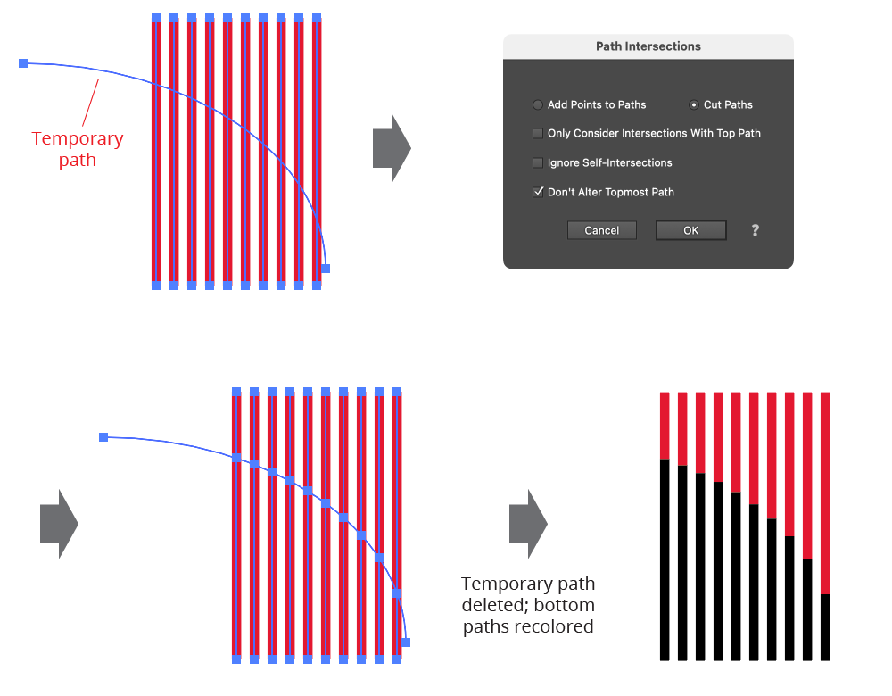
Path Intersections Example
6. Help Button
Opens the help documentation in the Astute Manager. If this does not automatically appear, please ensure your Astute Manager is running first.
Illustrator Location:
Illustrator Main Menu > Effect > AG Utilities > ...
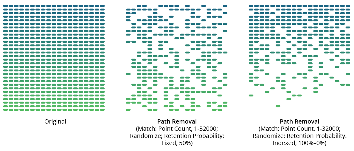
Path Removal is an Astute Graphics live effect that removes paths from the object it is applied to, based on criteria such as path length, type (open/closed), or index. It is most useful when applied to a group of many paths, or is preceded by another live effect which breaks one path into many, such as Astute’s Dashify or Split Path to Segments.
As with most live effects, Path Removal appears in the main menu, under Effect > AG Utilities. It can also be applied directly from the Appearance panel using the “Add New Effect” button at the bottom of the panel.
Path Removal Parameters Dialog
After applying the live effect using the menu item (or when clicking on the existing effect in the Appearance panel to edit it), the parameters dialog will appear:

Path Removal Parameters Dialog
1. Criteria Popup
By default, paths will be removed only if they match all of the enabled options (the first six checkboxes below). However you can change this to When They Match Any Enabled Options, Unless They Match All Enabled Options, or Unless They Match Any Enabled Options.
2. Point Count
Paths match when they have an anchor point count from the minimum to the maximum values specified. The defaults are both 1, meaning paths will match if they are single points. When compound paths are treated as a whole, the anchor point count is the sum of all the anchor points in all subpaths.
3. Length
Paths match when they have a length from the minimum to the maximum values specified. When compound paths are treated as a whole, the length is the sum of the lengths of all subpaths.
4. Type
Paths match when their type is the same as specified. When compound paths are treated as a whole, they match if all of the subpaths match.
5. Subpaths of a Compound Path
Paths match as specified.
6. Segments With Handles
When set to Yes, paths match if any of their segments have handles; when set to No, paths match if none of their segments have handles.
7. Index
Paths match if their index matches the specified indices. Paths are assigned indices starting at zero, increasing in the order in which they are encountered within the live effect. The default type of index match is Odd, i.e. 1, 3, 5, 7, etc. Other options are First, Last, First or Last, Even, and Pattern. Pattern type creates a repeating pattern of matching indices based on the three subsequent parameters.
8. Initial Skip
For Pattern index matching, the initial number of indices to skip over.
9. Match
For Pattern index matching, the number of indices to match after skipping some.
10. Skip
For Pattern index matching, the number of indices to skip over after matching some.
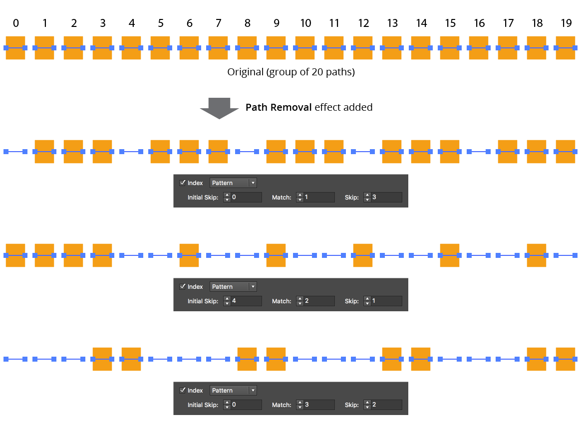
AG Utilities Live Effects - Path Removal Pattern
11. Randomize
Allows randomization of the removal.
12. Seed
Each random seed number leads to a different sequence of random values. Clicking the button picks a new seed, thereby changing the look of the artwork. To view or specify the seed number directly, Option/Alt-click the button. This lets you recreate a previously-generated look.
13. Retention Probability
The probability that a path that would normally be removed under the previous criteria will instead be retained. This value can be fixed (the default) or based on the index.
14. Retention Probability Value
For Fixed probability, the fixed value that applies to all removed paths. When the probability is set to Indexed, it consists of a starting probability value and an ending probability value, which linearly changes based on the index of the path.
AG Utilities Live Effects - Path Removal Randomization Retention
15. Keep Same Geometry Paths Together
When the Path Removal effect is positioned under an artwork’s strokes and fills in the Appearance panel, the stroked and filled paths are passed to it separately, and would therefore normally be randomly affected independently, leading to some paths being stroked but not filled and vice versa. Sometimes this can be solved by simply moving the Path Removal effect above them in the Appearance panel, but depending on the other effects that are present, this may not always be possible. In that case, enabling this setting allows paths with the exact same underlying geometry (such as fills and strokes of the same path) to be retained or removed in a unified manner.
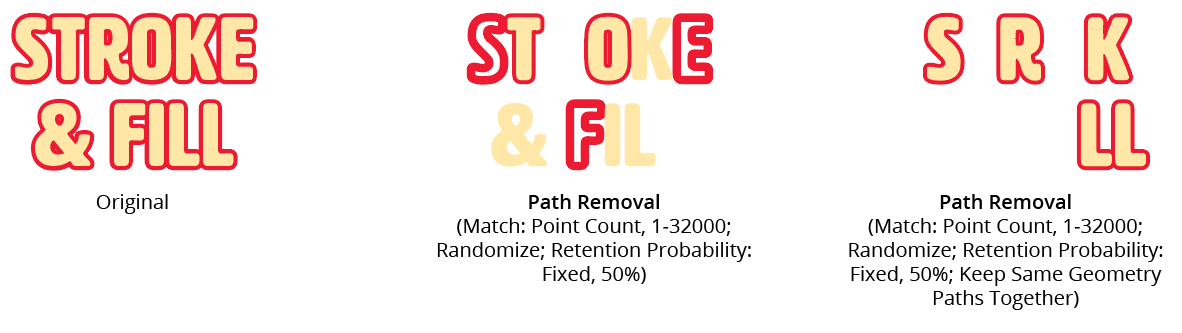
AG Utilities Live Effects - Path Removal Keep Same Geometry Together
16. Treat Compound Paths As a Whole
Normally each subpath of a compound path is examined for possible removal independently. When this setting is enabled, compound paths are either removed in their entirety or retained in their entirety. Some of the match parameters are interpreted slightly differently (for example, Point Count is interpreted to mean the total number of anchor points in all of the compound path’s subpaths).
17. Preview
As with all live effects, when enabled, changing a parameter will immediately update the artwork while the dialog is still open.
18. Help Button
Opens the help documentation in the Astute Manager. If this does not automatically appear, please ensure your Astute Manager is running first.
Illustrator Location:
Illustrator Main Menu > Effect > AG Utilities > ...
Reverse Path Direction is an Astute Graphics live effect with one simple function: to reverse the directions of all paths. It has no parameters.
As with most live effects, Reverse Path Direction appears in the main menu, under Effect > AG Utilities. It can also be applied directly from the Appearance panel using the “Add New Effect” button at the bottom of the panel.
For paths that are not subsequently brushed, have arrowheads, or are affected by another live effect that depends on path direction (such as Make Shape), Reverse Path Direction will generally not show any visible changes.
Illustrator Location:
Illustrator Main Menu > Effect > AG Utilities > ...
Segment Removal is an Astute Graphics live effect that removes segments from the paths in the artwork to which it is applied, based on criteria such as their length, handle status, or index. When segments are removed, the path is split into multiple paths (unless the segments are contiguous in a closed path, in which case the path becomes an open path).
As with most live effects, Segment Removal appears in the main menu, under Effect > AG Utilities. It can also be applied directly from the Appearance panel using the “Add New Effect” button at the bottom of the panel.
Segment Removal Parameters Dialog
After applying the live effect using the menu item (or when clicking on the existing effect in the Appearance panel to edit it), the parameters dialog will appear:

Segment Removal Parameters Dialog
1. Criteria Popup
By default, segments will be removed only if they match all of the enabled options (the first four checkboxes below). However you can change this to When They Match Any Enabled Options, Unless They Match All Enabled Options, or Unless They Match Any Enabled Options.
2. Length
Segments match when they have a length (as measured along the path) from the minimum to the maximum values specified.
3. At Least One Handle
When set to Yes, segments match if they have one or two handles; when set to No, segments match if they have no handles (thus are straight).
4. Index
Segments match if their index matches the specified indices. Segments are assigned indices starting at zero, increasing in the order in which they are encountered within the live effect across multiple paths or subpaths. The default type of index match is Odd, i.e. 1, 3, 5, 7, etc. Other options are First, Last, First or Last, Even, and Pattern. Pattern type creates a repeating pattern of matching indices based on the three subsequent parameters.
5. Initial Skip
For Pattern index matching, the initial number of indices to skip over.
6. Match
For Pattern index matching, the number of indices to match after skipping some.
7. Skip
For Pattern index matching, the number of indices to skip over after matching some.
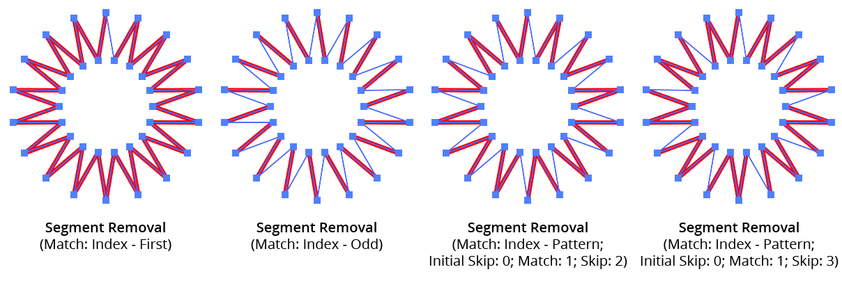
AG Utilities Live Effects - Segment Removal Pattern
8. Randomize
Allows randomization of the removal.
9. Seed
Each random seed number leads to a different sequence of random values. Clicking the button picks a new seed, thereby changing the look of the artwork. To view or specify the seed number directly, Option/Alt-click the button. This lets you recreate a previously-generated look.
10. Retention Probability
The probability that a segment that would normally be removed under the previous criteria will instead be retained.
11. Keep Same Geometry Paths Together
When the Segment Removal effect is positioned under an artwork’s strokes and fills in the Appearance panel, the stroked and filled paths are passed to it separately, and their segments would therefore normally be randomly affected independently, leading to some paths having different segments removed when Randomize is enabled. Sometimes this can be solved by simply moving the Segment Removal effect above them in the Appearance panel, but depending on the other effects that are present, this may not always be possible. In that case, enabling this setting allows paths with the exact same underlying geometry (such as fills and strokes of the same path) have the same segments removed or retained.
12. Preview
As with all live effects, when enabled, changing a parameter will immediately update the artwork while the dialog is still open.
13. Help Button
Opens the help documentation in the Astute Manager. If this does not automatically appear, please ensure your Astute Manager is running first.
Illustrator Location:
Split Path to Segments is an Astute Graphics live effect that breaks a path at its anchor points into multiple segments. Paths can be split at corner points, sharp points, or all points.
As with most live effects, Split Path to Segments appears in the main menu, under Effect > AG Utilities. It can also be applied directly from the Appearance panel using the “Add New Effect” button at the bottom of the panel.
Split Path to Segments Parameters Dialog
After applying the live effect using the menu item (or when clicking on the existing effect in the Appearance panel to edit it), the parameters dialog will appear:
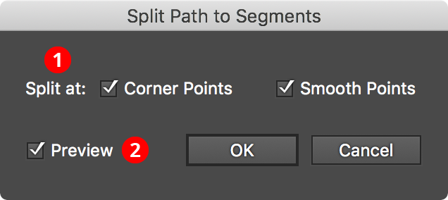
Split Path to Segments Parameters Dialog
1. Split At
Specifies which types of anchor points at which splits should occur: corner, smooth, or both.
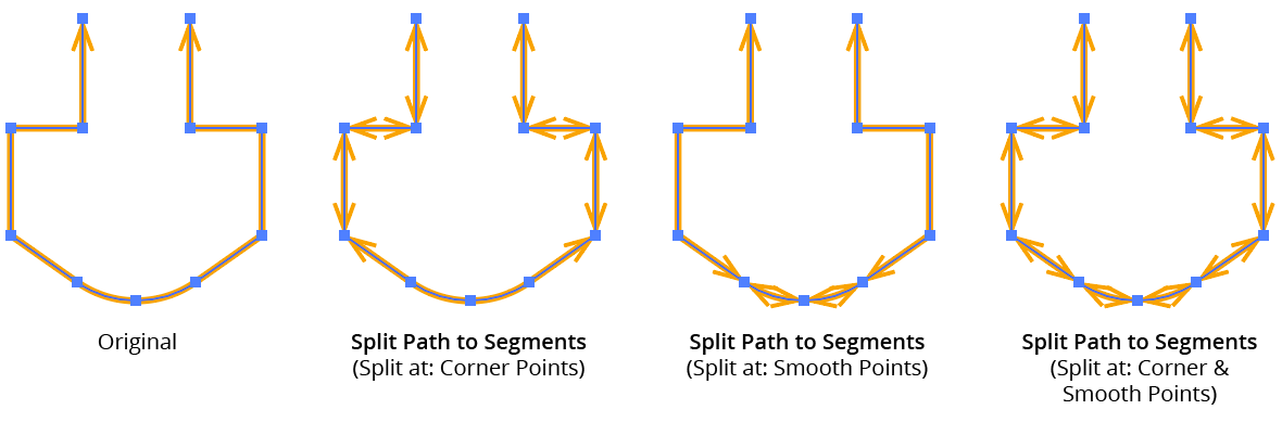
AG Utilities Live Effects - Split Path to Segments Examples
2. Filter By Index
When enabled, each anchor point’s index (starting with zero on each path) is used to determine whether the path will be split at that point. Filter by Index has seven different methods, as follows:
a. First: Each path will be split at the first n points, where n is the specified value.

Split Path to Segments Filter by Index First Controls
b. Last: Each path will be split at the last n points, where n is the specified value.

Split Path to Segments Filter by Index Last Controls
c. First or Last: Only the first and last points will be used as split points.
d. Odd: Only points with an odd index (1, 3, 5, 7...) will be used as split points.
e. Even: Only points with an even index (0, 2, 4, 6...) will be used as split points.
f. Pattern: Creates a repeating pattern of matching indices based on the three pattern parameters.
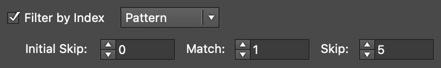
Split Path to Segments Filter by Index Pattern Controls
Initial Skip specifies the number of indices to skip over at the start (the path will not be split at points with these indices). Then, Match specified the number of indices that will match and therefore cause splits. Finally, Skip specifies the number of indices to skip over following the matching indices. When the total of the values in the three parameters is less than the number of anchor points, the pattern repeats, using the Match and Skip values in alternation.
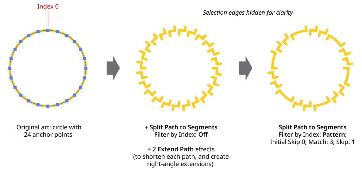
Split Path to Segments Filter by Index - Pattern
g. Randomly: At each anchor point, the path has the specified random chance (from 0% to 100%) of being split. Clicking the Seed button picks a new random seed, thereby changing the look of the artwork. To view or specify the seed number directly,
Option/Alt-clickthe button. This lets you recreate a previously-generated look.

Split Path to Segments Filter by Index Randomly Controls
3. Preview
As with all live effects, when enabled, changing a parameter will immediately update the artwork while the dialog is still open.
3. Help Button
Opens the help documentation in the Astute Manager. If this does not automatically appear, please ensure your Astute Manager is running first.
Illustrator Location:
Illustrator Main Menu > Window > Astute Graphics > QuickOps
The Trim Open Paths operation is used to trim off one or multiple selected open paths where they are intersected by other visible, unlocked paths (or by self-intersections). By default, the trimming can occur from either end of the path (the shorter end, if the path is intersected only once; otherwise both ends), but Shift can be held while clicking the button to force trimming from only one end; which end depends on the preferences setting.
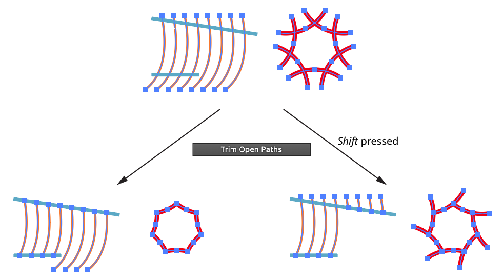
QuickOps Trim Open Paths
Clicking the icon to the right of the button will bring up the Trim Open Paths Preferences dialog:
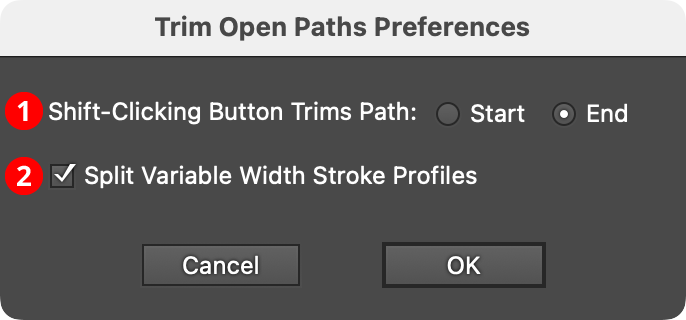
QuickOps Trim Open Paths Preferences
1. Shift-Clicking Button Trims Path
Specifies which side of the path to trim if the button is clicked with Shift held down.
2. Split Variable Width Stroke Profiles
When enabled, and the trimmed path has a variable width stroke, the stroke profile will be split to keep the width of the untrimmed section as close to the original as possible.
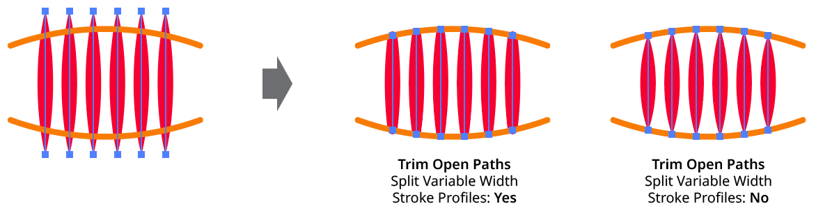
QuickOps Trim Open Paths - Split Variable Width Profiles