 Perpendicular Line Tool
Perpendicular Line is an Astute Graphics tool for Adobe Illustrator that creates straight paths that are perpendicular to one or two existing paths. A special function allows you to create multiple perpendicular lines along a path segment or an entire path, with or without randomization. Perpendicular Line is part of the SubScribe plugin.
Tool Location and Cursor Appearance
The Perpendicular Line tool appears in Illustrator’s main toolbar (which must be in Advanced mode: View > Toolbars > Advanced) stacked under the Tangent Line tool. As with other stacked tools, click and hold on the top tool icon to display the tools stacked under it.
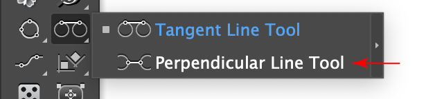
Perpendicular Line Tool Location
The Perpendicular Line tool’s cursor is a standard crosshair, with a dot next to it when the Add Points to Existing Paths preference is enabled:
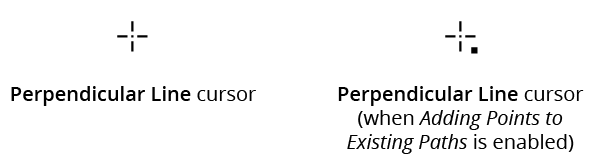
Perpendicular Line Tool Cursors
Perpendicular Line Tool Operation
As the Perpendicular Line tool has many keypresses which can add or change its functionality, we suggest installing the free Astute Graphics plugin Astute Buddy, which creates a panel that dynamically updates to inform you of the various keys which can be pressed in the tool’s current context.
Creating a line perpendicular to one existing path
A line may created that is perpendicular to an existing path by either starting on the path and drawing the line away from it, or by starting at another location and drawing the line to the path. Either way, after clicking on the first location, the mouse button can be released and a second click made on the second location, or the cursor can be dragged to the second location. The first method allows scrolling, zooming, changing the view mode, etc. in the middle of the operation, but the second method allows additional keypresses that only work with the mouse button down (see below).
When the cursor is snapping perpendicularly to an existing path, the snap point will be highlighted with a small, semi-transparent green square. A small letter “P” will also be drawn if the cursor is snapping to an anchor point, and an “M” when the cursor is snapping to the midpoint of a straight path segment.
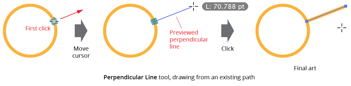
Perpendicular Line Tool - From Existing Path
When drawing a perpendicular line away from a path, the Shift key can be held down to constrain the line’s length to “nice” values, dependent on the current zoom level and units. For example, at 200% zoom, its length is constrained to multiples of 2 pt or 0.5 mm. Additionally, if the cursor is being dragged (mouse button down), the following keys can be pressed:
Command/Ctrl: Overrides snapping to a second path.
A: Cycles through the different Multi-Line modes (see Perpendicular Line: Multi-Line Modes).
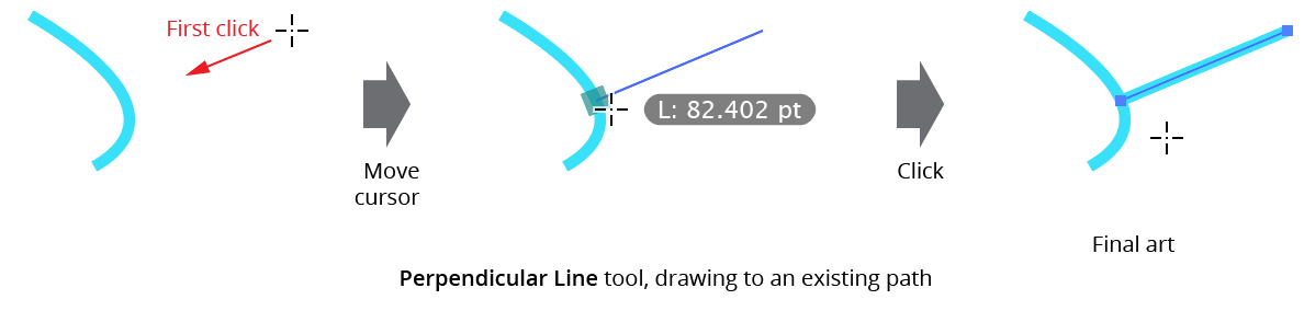
Perpendicular Line Tool - Drawing to an Existing Path
When drawing a perpendicular line to an existing path, if the path contains multiple spots of perpendicularity, then the one closest to the cursor is chosen.
Creating a line perpendicular to two existing paths
If the line is started along a path, and the cursor is subsequently brought close to another path, then, if the line can be positioned so it is perpendicular to both paths, it snaps to the second path (unless being dragged and Command/Ctrl is being pressed) and the line’s start and end positions are both adjusted. If there are multiple places where a suitable line can be created, then the spot which ends closest to the cursor is chosen.
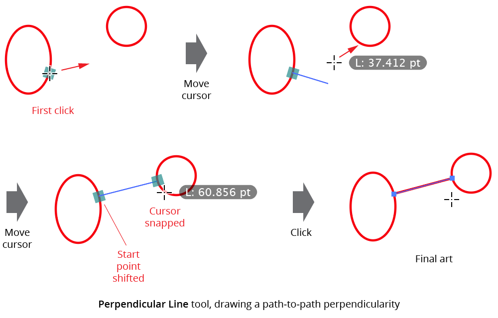
Perpendicular Line Tool - Line Between Two Paths
Sometimes it is necessary to create a line which starts at a specific spot along a path and is perpendicular only to the second path. In this case, pressing the key assigned to “Increase Diameter” in the native Keyboard Shortcuts dialog (by default, for English-speaking locales, the right bracket key “]”) will tell the Perpendicular Line tool to ignore the start path when finding perpendicularities; the initial green square snapping annotation will turn gray to indicate that the line is no longer being forced to be perpendicular at the start point. Pressing the key again will return to the normal two-perpendiculars mode.
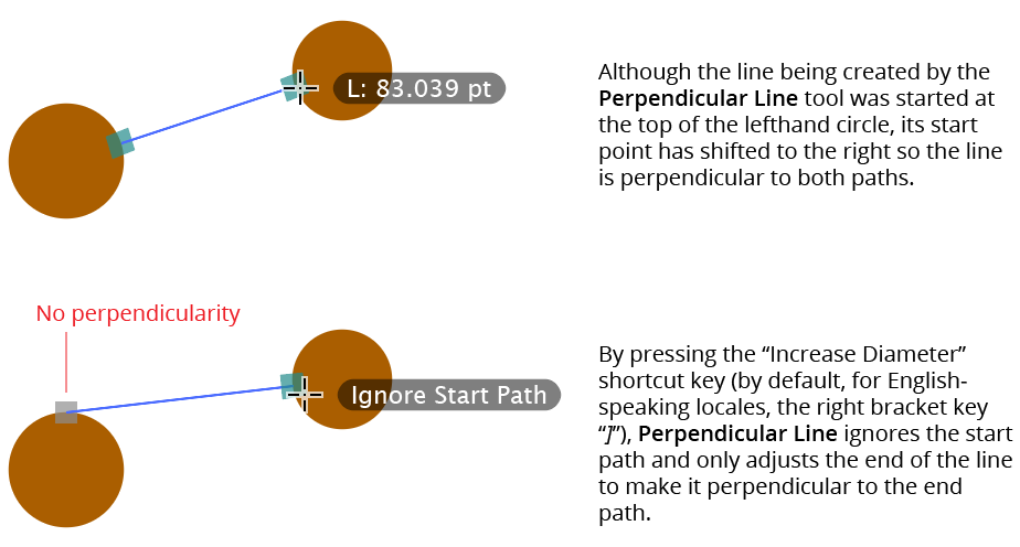
Perpendicular Line Tool - Ignore Starting Path
You can switch between the Perpendicular Line tool and the Tangent Line tool (except when dragging) by pressing the key assigned to “Decrease Diameter” in the native Keyboard Shortcuts dialog (by default, for English-speaking locales, the left bracket key “[”).
Perpendicular Multi-Line Modes
Multi-Line modes can be activated and cycled through by pressing the A key when dragging the line from a path. When a Multi-Line mode is active, the Perpendicular Line tool will create multiple perpendicular lines from the path, not just a single one. There are three different Multi-Line modes:
Multi-Line/Segment: Lines are drawn along the path segment.
Multi-Line/Path: Lines are drawn along the entire path.
Multi-Line/Anchors: A line is drawn from each anchor point of the path.
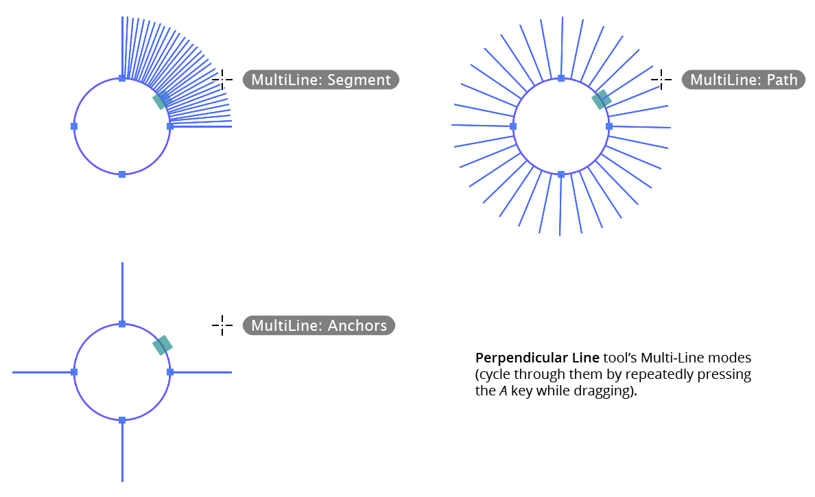
Perpendicular Line Tool - Multi-Lines Mode
While dragging in Multi-Line mode, there are additional keypresses available:
Up Arrow/Down Arrow: Except when in Anchors sub-mode, the arrow keys adjust the number of lines (from 2 to 8000; retained across sessions).
C: Toggles centering mode. When centering mode is enabled, each line is drawn centered on the path rather than just to one side (in this case the displayed length actually indicates half of the line). The centering mode is retained between uses of the tool.
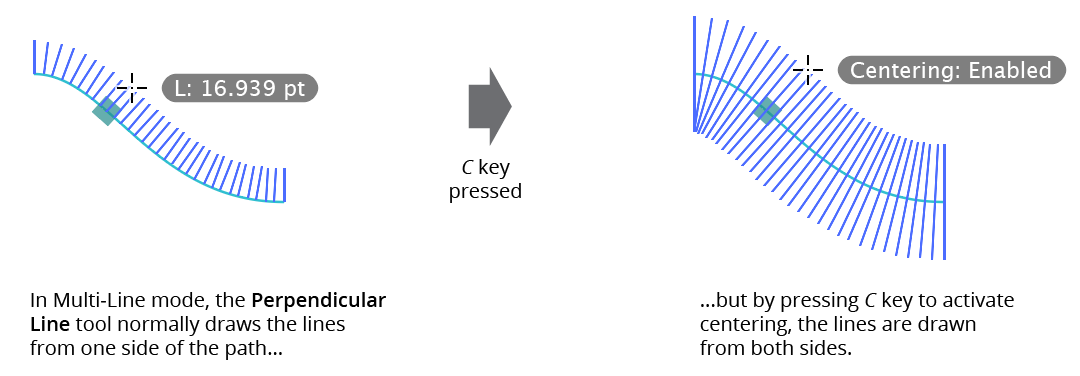
Perpendicular Line Tool - Multi-Line Centering Enabled
G: Toggles grouping mode. Normally the multiple lines that are created are put into a single group for ease in subsequent selection, but by turning grouping off, they will not be grouped. The grouping mode is retained between uses of the tool.
O: Toggles overlap mode (available for Segment sub-mode only). By default, multiple lines are created along an entire segment; i.e. a line is created at its start and another at its end. However, this creates a problem if lines are first drawn from one segment and then from an adjacent segment, because the end of one segment is at the same position as the start of the next segment, and the two lines on the end will overlap. To remedy this, when overlapping is turned off, a line will not be drawn at the very end of the segment. The overlap mode is retained between uses of the tool.
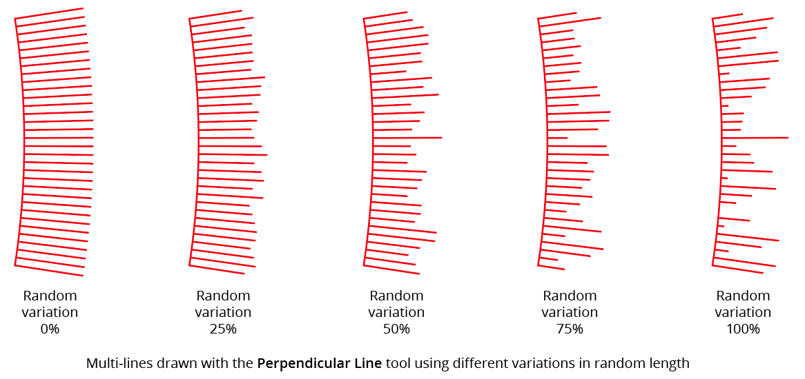
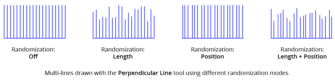
R: Turns on randomization (if off) and cycles it through three modes: Length, Position, and Length + Position. The randomization mode is retained between uses of the tool. In all three modes, the variation parameter can be adjusted (between 0% and 100%) by pressing the Left Arrow and Right Arrow keys.
In Length mode, the lengths of each line will be randomly varied by an amount equal to the random variation parameter, with the maximum value representing 0% variation. For example, if the length is being held at 40 pt, and the random variation is set to 75%, then the lengths can vary by 40 pt × 75% or 30 pt, resulting in final values of 10 pt to 40 pt.
Perpendicular Line Tool - Random Variation Mode
In Position sub-mode, the positions of each line will be randomly varied in the same manner.
In Length + Position sub-mode, both the lengths and the positions of each line are randomly varied.
Perpendicular Line Tool - Randomization Mode
Perpendicular Line Preferences
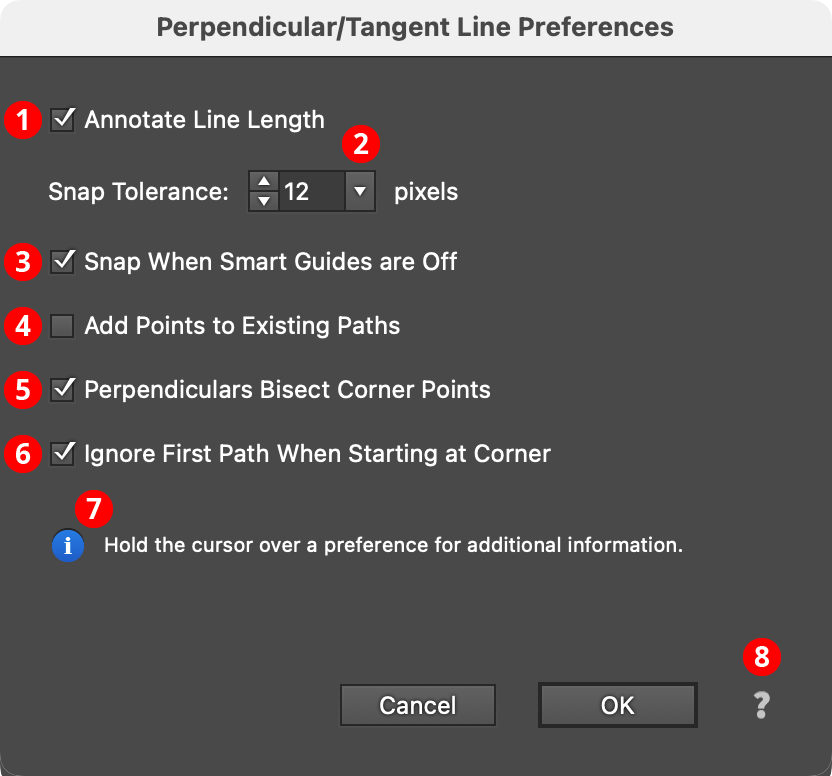
Doubleclicking the Perpendicular Line tool in the toolbox (or pressing the Enter key when the tool is selected) will bring up its preferences dialog, which it shares with the Tangent Line tool:
Perpendicular Line Preferences
1. Annotate Line Length
When enabled, the current length of the perpendicular line is displayed next to the cursor.
2. Snap Tolerance
The tolerance for the cursor when snapping to existing paths. If Smart Guides are turned on, the Smart Guides tolerance value is used if it is larger than the specified value.
3. Snap When Smart Guides are Off
When enabled, and Smart Guides are turned off, the cursor will still snap to paths using the specified Snap Tolerance.
4. Add Points to Existing Paths
When enabled, anchor points will be added to the existing path(s) at the points where the perpendicular line begins or ends. A dot appears next to the cursor to indicate that this mode is active. The preference may be inverted on the fly by pressing the Option/Alt key when using the tool.
5. Perpendiculars Bisect Corner Points
When enabled (the default), corner anchor points are considered to have a perpendicular which bisects the angle made by the path at that point; otherwise, the perpendicular is made to the angle of the path entering or leaving the point.
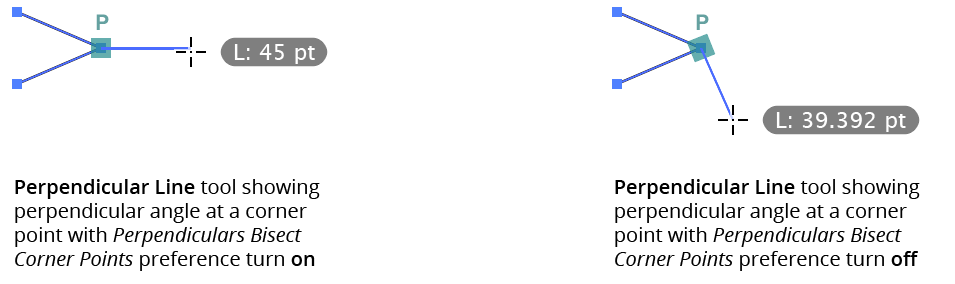
Perpendicular Line - Bisect Preference
6. Ignore First Path When Starting at Corner
When enabled (the default), and a path-to-path line is begun at a corner anchor point, the first path is ignored for the purposes of making the line perpendicular to it. To ignore the first path even when not starting on a corner point, use the Increase Diameter keyboard shortcut key (see Perpendicular Line: Tool Operation).
7. Informational area
Shows a brief description of each preference control when the cursor is being hovered over it.
8. Help Button
Opens the help documentation in the Astute Manager. If this does not automatically appear, please ensure your Astute Manager is running first.