 QuickOps
-
QuickOps Panel
- Guide Through Points
- Rectangle at Bounds
- Rectangle at Bounds (Text)
- Shift Art
- Center-Center Objects
- Expand-Expand Appearance
- Distribute to Grid
- Align Pattern
- Text-Aware Reflect
- Scale Justify
- Trim Open Paths
- Set Bounding Box Angle
- Scale Strokes
- Make/Release Type On Path
- Reduce Colors
- Delete Unused Panel Items
- Rename Swatches
- Group By Proximity
- QuickOps Panel Flyout Menu
- Actionability
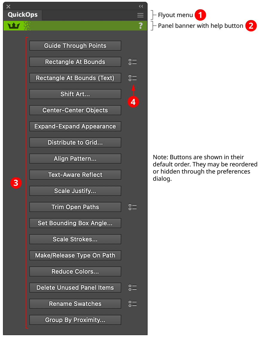
QuickOps is an Astute Graphics panel for Adobe Illustrator that provides fast, one-click access to a number of useful operations. These include: creating a rectangle around the bounds of a piece of art, centering art along both axes on the current artboard, organizing selected art into a grid, specifying the origin of a pattern used in an art object, and more. Some of the operations include a Shift-click alternate mode, and some use a small dialog to change various settings. The operations that are displayed on the panel, as well as their order, can be customized. QuickOps is part of the SubScribe plugin.
QuickOps Panel
QuickOps Panel
1. Flyout Menu
See QuickOps Panel: Flyout Menu.
2. Panel Banner
The QuickOps panel banner has a help button on the right which opens the help documentation in the Astute Manager. If this does not automatically appear, please ensure your Astute Manager is running first.
3. Operation Buttons
Each button can be clicked when the current selection is compatible with its operation. The order of the buttons can be changed, and, if there are operations that are rarely or never used in your workflow, those buttons can be hidden to make the panel smaller (see QuickOps Panel: Flyout Menu).
Some operations have an alternate mode, which can be accessed by holding down the Shift key when clicking the button.
For details about each operation, see other documentation pages.
4. Preference Indicators
Operations with customizable preferences have an icon to their right. Clicking the icon brings up a small dialog with preferences which are specific to that operation.
Guide Through Points
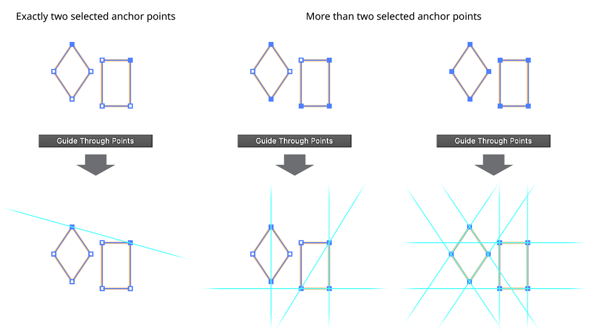
The Guide Through Points operation creates a straight-line guide that passes through the selected two anchor points. If more than two anchor points are selected, the operation works on an path-by-path basis (ignoring groups). Paths with fewer than two selected anchor points are ignored. Otherwise, guides are created through successive pairs of the path’s selected anchor points, working around the path in the order in which they are encountered. For example, if a path with seven anchor points has points 0, 3, and 5 selected, then three guides would be created: a) through points 0 and 3; b) through points 3 and 5; and c) through points 5 and 0.
QuickOps Guide Through Points
Rectangle at Bounds
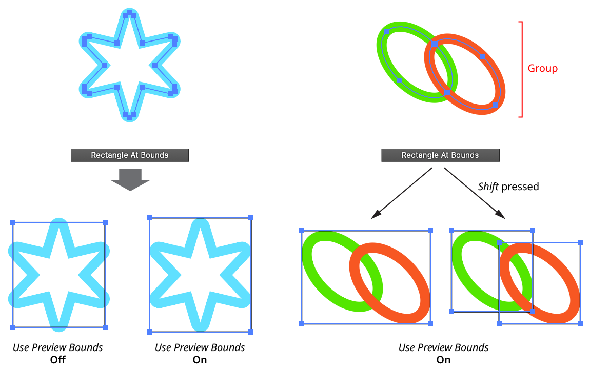
The Rectangle At Bounds operation creates a rectangular path around the orthogonally-aligned bounds of each selected art object. The operation honors the general Illustrator preference Use Preview Bounds. Groups are treated as a single object unless Shift is held down when the button is clicked.
QuickOps Rectangle at Bounds
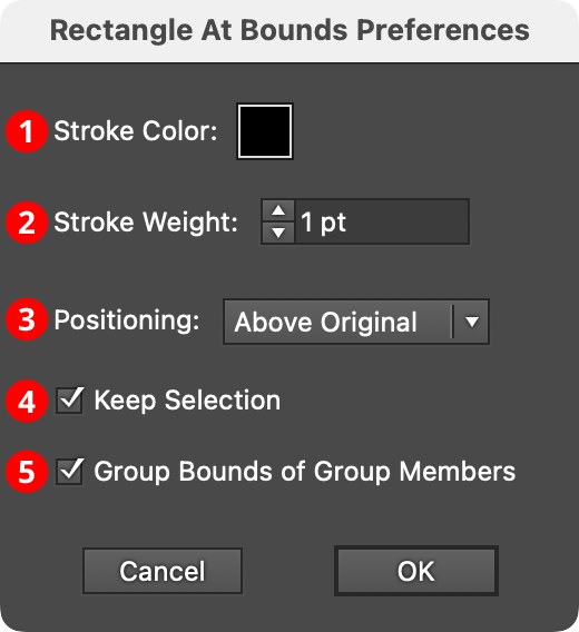
Clicking the icon to the right of the button will bring up the Rectangle At Bounds Preferences dialog:
QuickOps Rectangle at Bounds Preferences
1. Stroke Color
Specifies the color of the rectangles. Clicking the color chip brings up the standard color picker dialog. The default color is black.
2. Stroke Weight
Specifies the stroke weight of the rectangles. The default weight is 1 pt.
3. Positioning
Specifies whether the bounds rectangles are created above the original art, below the original art, or to replace the original art.
4. Keep Selection
When enabled, the original art stays selected; otherwise the bounds rectangles become the new selection.
5. Group Bounds of Group Members
When Shift is used to create multiple bounds rectangles for each member of a group, these rectangles are also placed in a group when this preference is enabled.
Rectangle at Bounds (Text)
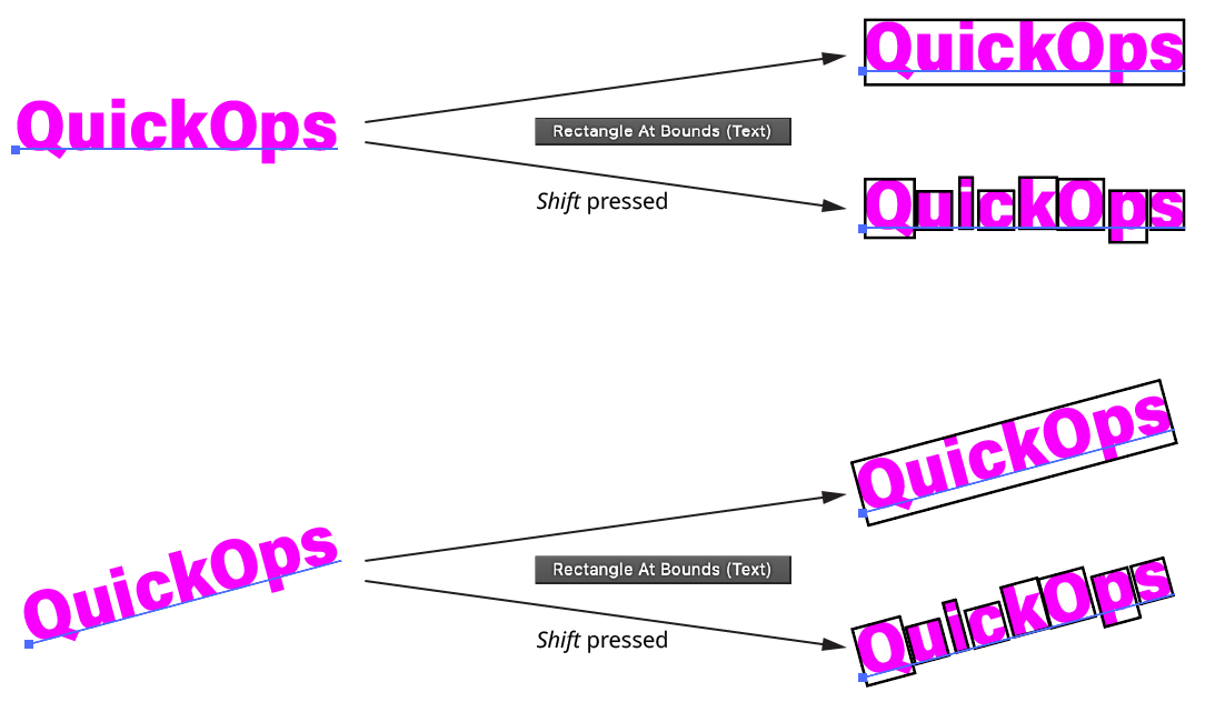
The Rectangle At Bounds (Text) operation creates a rectangular path around the bounds of each selected text object, treating it as if the text were outlined. The operation honors the general Illustrator preference Use Preview Bounds (although unless the text has live effects attached to it, this will generally not matter since text is not typically stroked). If the Shift key is held down when the button is clicked, then bounds rectangles are drawn around each glyph in the text object. If the text object is scaled, rotated, or sheared, the bounds rectangle(s) will reflect that transformation matrix.
QuickOps Rectangle at Bounds - Text
Clicking the icon to the right of the button will bring up the Rectangle At Bounds (Text) Preferences dialog:
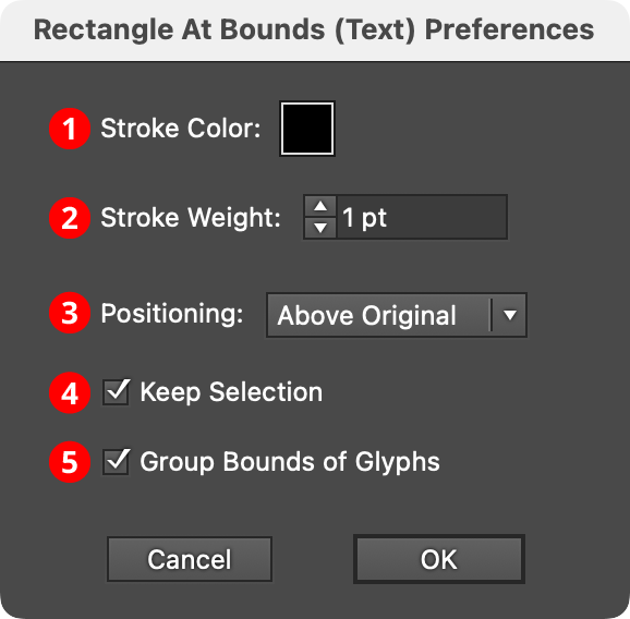
QuickOps Rectangle at Bounds - Text Preferences
1. Stroke Color
Specifies the color of the rectangles. Clicking the color chip brings up the standard color picker dialog. The default color is black.
2. Stroke Weight
Specifies the stroke weight of the rectangles. The default weight is 1 pt.
3. Positioning
Specifies whether the bounds rectangles are created above the original text art, below the original text art, or to replace the original text art.
4. Keep Selection
When enabled, the original art stays selected; otherwise the bounds rectangles become the new selection.
5. Group Bounds of Glyphs
When Shift is used to create multiple bounds rectangles for each glyph, these rectangles are also placed in a group when this preference is enabled.
Shift Art
The Shift Art... operation allows art to be moved directly to a specific numerical position without dragging it. With artwork selected, clicking the button will switch the current tool to a special temporary one that snaps (with a red ring) to anchor points, image corners, text origin points, etc., as it is moved over the selected art. When it is above the desired reference point, clicking with the tool will bring up a small dialog which lets you specify the desired numerical position of that reference point (clicking on anything other than a reference point or pressing the Esc key will cancel the operation).
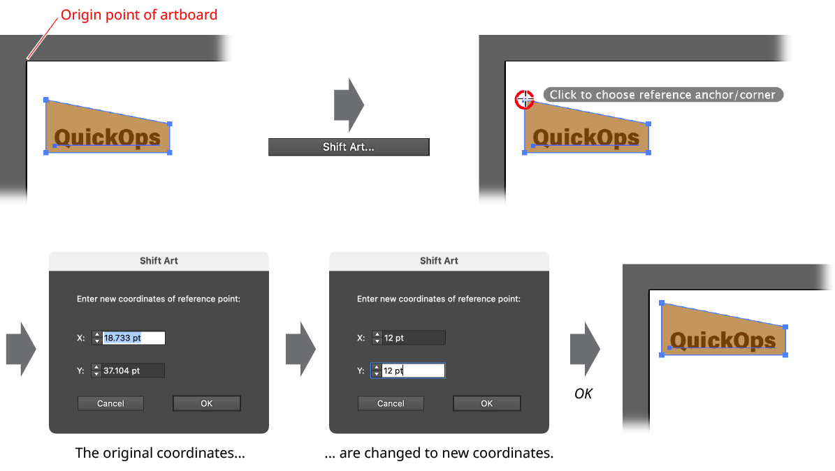
QuickOps Shift Art Example
When the OK button is pressed, all of the selected art will be shifted (as one unit) such that the reference point lands exactly at the specified numerical coordinates. The tool will then automatically switch back to the previously-selected tool.
Center-Center Objects
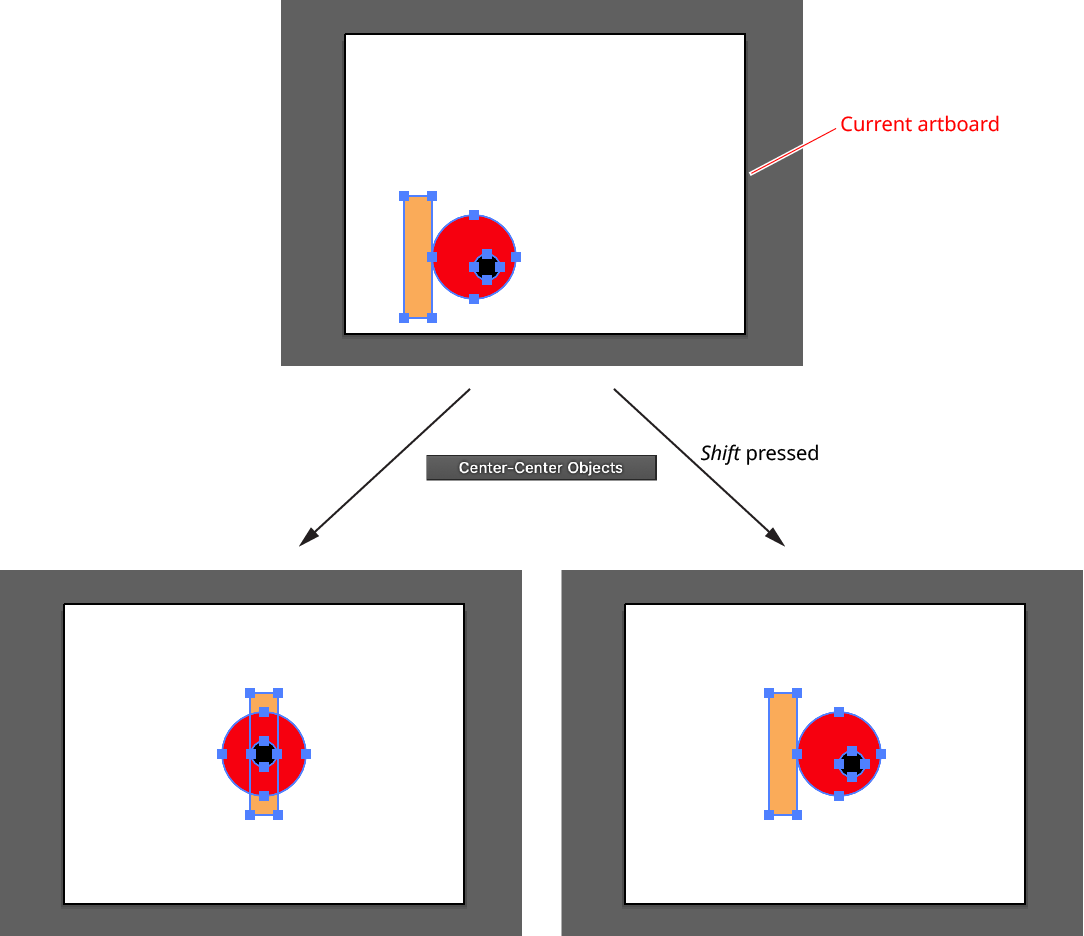
The Center-Center Objects operation simply moves each of the selected objects to the center (both horizontally and vertically) of the current artboard. If Shift is held while clicking the button, the selected art is treated as if it were grouped (that is, it is moved as a single unit).
QuickOps Center Center Objects
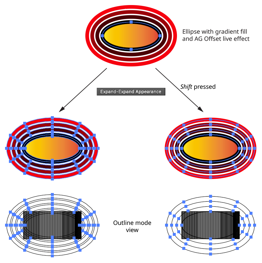
Expand-Expand Appearance
The Expand-Expand Appearance operation is equivalent to using two menu commands on the selected art: Expand Appearance, followed by Expand..., with the Fill and Stroke options turned on, and Expand Gradient Mesh set to “128 Objects”. If Shift is held while clicking the button, strokes will not be expanded.
QuickOps Expand Expand Appearance
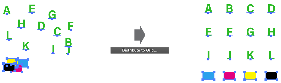
Distribute to Grid
The Distribute to Grid operation moves the selected artwork into a rectangular grid formation. The center of the grid is placed at the center of the bounds of the original selected art.
QuickOps Distribute to Grid Overview
Clicking the button brings up the settings dialog:
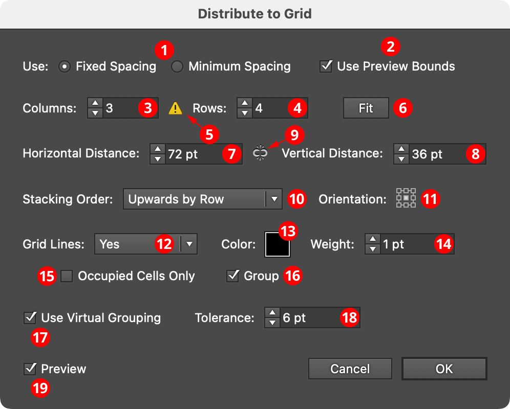
QuickOps Distribute to Grid Settings
1. Spacing
The two grid spacing options are Fixed Spacing and Minimum Spacing.
In Fixed Spacing, the centers of the grid cells are placed a fixed distance apart, and therefore all of the cells are squares of the same size. If this distance (specified further down in the dialog) is less than the size of any of the pieces of filling art, that art will simply extend beyond the grid boundaries, and may overlap with the art in adjacent cells.
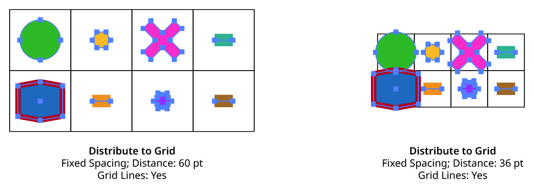
QuickOps Distribute to Grid Fixed Spacing
In Minimum Spacing, each grid cell is only as wide as the widest piece of art in its column (and only as tall as the tallest piece of art in its row) plus the distance value specified further down in the dialog. If all the art were the same size, this distance value would be equivalent to a gutter width/height.
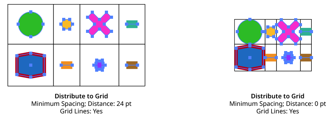
QuickOps Distribute to Grid Minimum Spacing
Bounding boxes of clip groups are calculated using the clipping paths only, ignoring the clipped content.
2. Use Preview Bounds
Overrides the general preference of the same name. When enabled, the strokes and live effects of the artwork are included in its bounding box, which affects the cell size (when spacing is set to Minimum Spacing) and the position of the art within the cell based on the orientation setting.
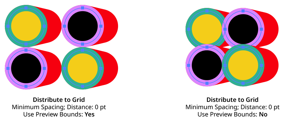
QuickOps Distribute to Grid Use Preview Bounds
3. Columns
Specifies the number of columns in the grid, from 1 to 1000.
4. Rows
Specifies the number of rows in the grid, from 1 to 1000.
5. Underflow Warning
If one or more of the selected art objects will fit into the grid (because the number of cells in the grid is less than the number of objects), the warning icon will be displayed and the Fit button will become available. If the dialog is OK’d regardless, the objects which did not fit are simply left at their original positions.
6. Fit
Available when the grid size is too small to contain all of the selected art objects. Clicking the button will automatically adjust the column and row counts to accommodate all of the objects. Holding down Option/Alt while clicking will only adjust the column count, while holding down Shift will only adjust the row count.
7. Horizontal Distance
When using Fixed Spacing, the horizontal distance value specifies the distance between the horizontal centers of each cell in the grid (i.e., the cell width). When using Minimum Spacing, the distance value specifies the extra space added (or removed) between columns after they have been adjusted to the minimum size needed to fit all the art. If all the art were the same size, this distance value would therefore be equivalent to a gutter width.
8. Vertical Distance
When using Fixed Spacing, the vertical distance value specifies the distance between the vertical centers of each cell in the grid (i.e., the cell height). When using Minimum Spacing, the distance value specifies the extra space added (or removed) between rows after they have been adjusted to the minimum size needed to fit all the art. If all the art were the same size, this distance value would therefore be equivalent to a gutter height.
9. Distance Link
When enabled (the link icon is unbroken), changing one distance value will automatically adjust the other in proportion. When disabled (the link icon is broken), each distance value can be adjusted independently.
10. Stacking Order
Specifies how the art should be placed into the grid, based on its original stacking order:
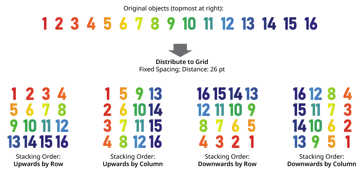
QuickOps Distribute to Grid Stacking Order
11. Orientation
The Orientation setting, specified using the standard “nine-block” control, indicates where in each cell the art will be positioned. When all the art is the same size, this generally does not produce any visible difference unless the grid lines are turned on.
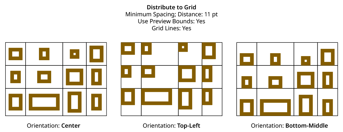
QuickOps Distribute to Grid Orientation
12. Grid Lines
There are three options for grid lines (stroked rectangles around each cell in the grid). When set to No, they are never created. When set to Preview Only, they are visible while the settings dialog is open, but are not actually created as artwork afterwards. When set to Yes, they are both previewed and left as artwork after the grid is created. Grid lines are always placed behind the artwork that forms the grid.
13. Color
Available unless Grid Lines are set to No. Specifies the color of the grid lines. Clicking the color chip brings up the standard color picker dialog. The default color is black.
14. Weight
Available unless Grid Lines are set to No. Specifies the stroke weight of the grid lines. The default is 1 pt.
15. Occupied Cells Only
Available unless Grid Lines are set to No. When enabled, only cells which contain art will have lines constructed.
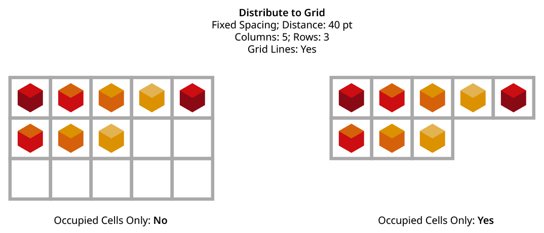
QuickOps Distribute to Grid - Grid Lines on Occupied Cells Only
16. Group
Available unless Grid Lines are set to No. When enabled, the rectangles which form the grid lines are placed into one group.
17. Use Virtual Grouping
When enabled, art objects are treated as if they had been Grouped By Proximity before being arranged into a grid (see Group By Proximity for details about the algorithm used). But, importantly, the grouping is not actually made, ensuring that items on different layers remain on those layers after being arranged into a grid.
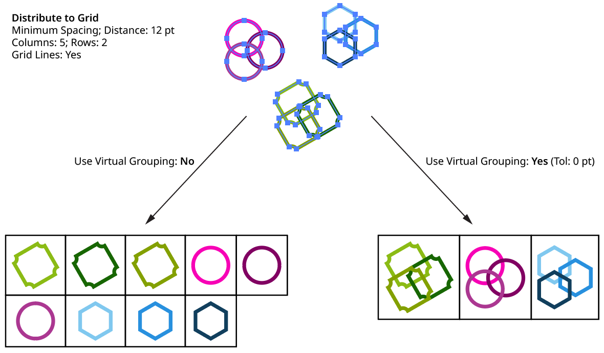
QuickOps Distribute to Grid Use Virtual Grouping
18. Tolerance
Available when Use Virtual Grouping is enabled. It controls how close together art objects must be before they are put into a virtual group. Larger values mean that objects that are further apart will still be considered “grouped.” See Group By Proximity for additional details.
19. Preview
When Preview is enabled, both the art objects’ final positioning and the grid lines (unless turned off) are shown on the artboard and will update whenever the settings are changed. Turning Preview off will show the objects in their original positions.
Align Pattern
The Align Pattern operation makes it possible to directly set the origin point of the patterns in one or more objects. With artwork containing at least one pattern selected, clicking the button will switch the current tool to a special temporary one (if the pattern(s) to be aligned are in the strokes of an object, Shift-click the button). The tool’s cursor can be snapped to anchor points, center points, etc. by using Smart Guides.
Selecting another tool or pressing Esc while moving the cursor will cancel the operation. Otherwise, when the cursor is in the desired position, click the mouse button and the pattern(s) will be shifted so their origin point is at the clicked point. The tool will then automatically switch back to the previously-selected tool.
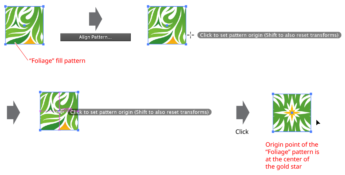
QuickOps Align Pattern Example
Aligning the pattern normally retains any transformation matrix that the pattern has (rotation, scaling, shearing). To align the pattern and also reset this matrix (removing the transforms), Shift-click with the tool.
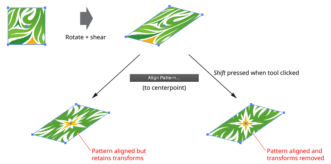
QuickOps Align Pattern Remove Transforms
Text-Aware Reflect
The Text-Aware Reflect operation reflects artwork either horizontally or vertically while keeping type objects (except text-on-a-path objects, which are not handled) unreflected and in the same relative position. The button is available when the selection contains at least one text object. This can be grouped with other art, but does not need to be. Clicking the button will reflect the selection horizontally (i.e., across the vertical axis); to reflect vertically, hold down Shift while clicking. Reflection is always through the center of the bounding box of the art.
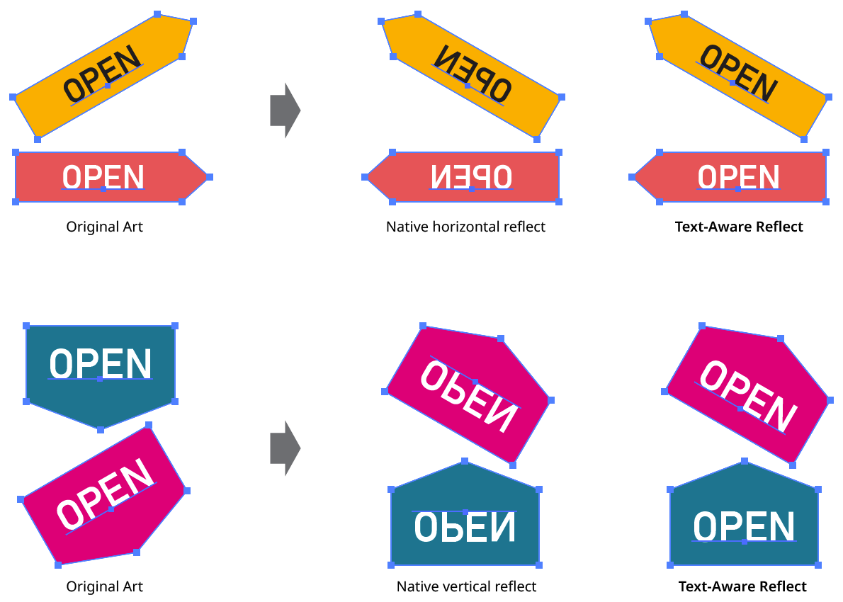
QuickOps Text Aware Reflect
Mixed case text with descenders may require minor adjustment of its vertical position after vertical reflection in order to keep it optically centered.
Scale Justify
The Scale Justify operation creates a single, justified column of text (sometimes known as “slab text”) from one or more selected text objects. Justification is done by scaling up each line of text to match the width of the longest line. Any text rotation is removed, and the top-to-bottom order of the text is retained.
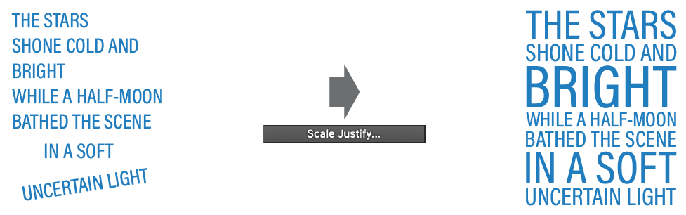
QuickOps Scale Justify Overview
With at least one text object selected (except text-on-a-path objects, which are not handled), clicking the button brings up the settings dialog:
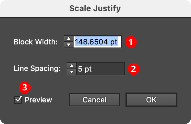
QuickOps Scale Justify Settings
1. Block Width
Specifies the width of the justified block of text. When the dialog is first brought up, the width will initially be set to that of the longest line of selected text, but it can be adjusted up or down as desired (from 1 pt to 4000 pt).
2. Line Spacing
Specifies the space between the lines of text, from –1000 pt to 1000 pt. When set to zero, the lines will just touch (remembering that glyphs with ascenders, descenders, serifs, or curves may make it appear as if there is still some space between the lines). Negative values can be used to create overlapping lines of type:
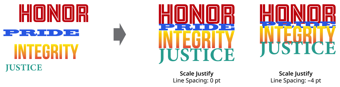
QuickOps Scale Justify Line Spacing
3. Preview
When Preview is enabled, the scale-justified text will be previewed on the artboard, and will update whenever the settings are changed. Turning Preview off will show the text in its original position.
Trim Open Paths
The Trim Open Paths operation is used to trim off one or multiple selected open paths where they are intersected by other visible, unlocked paths (or by self-intersections). By default, the trimming can occur from either end of the path (the shorter end, if the path is intersected only once; otherwise both ends), but Shift can be held while clicking the button to force trimming from only one end; which end depends on the preferences setting.
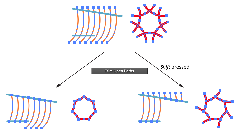
QuickOps Trim Open Paths
Clicking the icon to the right of the button will bring up the Trim Open Paths Preferences dialog:
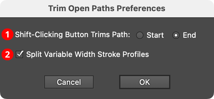
QuickOps Trim Open Paths Preferences
1. Shift-Clicking Button Trims Path
Specifies which side of the path to trim if the button is clicked with Shift held down.
2. Split Variable Width Stroke Profiles
When enabled, and the trimmed path has a variable width stroke, the stroke profile will be split to keep the width of the untrimmed section as close to the original as possible.
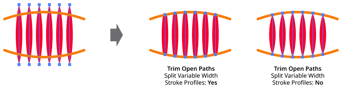
QuickOps Trim Open Paths - Split Variable Width Profiles
Set Bounding Box Angle
The Set Bounding Box Angle operation allows the selected art’s bounding box (as displayed by Illustrator when View > Show Bounding Box is turned on) to be numerically rotated to any value. This allows, for example, distortion of the object(s) in a certain direction by dragging a bounding box handle. Because the native main menu command Object > Transform > Reset Bounding Box only allows the angle to be changed to zero, achieving this natively would require three steps: rotating the object to the opposite of the desired angle, resetting the bounding box, and then rotating the object back to the desired angle.
With art selected, clicking the button will bring up a small dialog, in which the new angle can be entered:
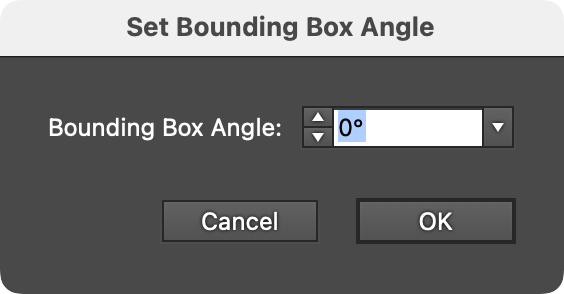
QuickOps Set Bounding Box Angle Dialog
By default, the initial angle will be set to the opposite of the document rotation (normally 0° unless the document view has been rotated). This allows for an interactive way to precisely set the angle: use the native Rotate View tool to rotate the document until the desired transformation direction of the selected art is horizontal, and then click the button and OK the dialog.
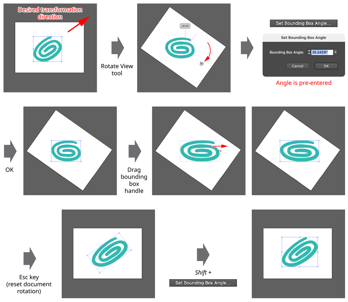
QuickOps Set Bounding Box Angle
Because native shapes like rectangles or ellipses have their own internal rotation value that overrides the normal one, setting the bounding box angle on a native shape will require it to become expanded. A small warning icon will be displayed on the dialog to indicate this.
After using the operation, with the art still selected, the button can be Shift-clicked to set the bounding box angle back to its original value.
Scale Strokes
The Scale Strokes operation allows the stroke weights of the selected art (but not the art itself) to be scaled up or down, in either an absolute or relative manner. A minimum weight can be specified, and final stroke weights can be rounded to a specified precision. Additionally, dashes, brushed strokes, and variable weight strokes can be selectively excluded from the scaling operation.
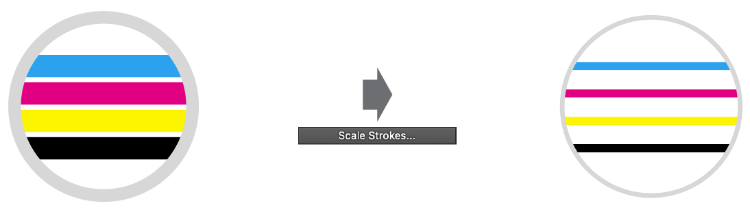
QuickOps Scale Strokes Overview
Clicking the button brings up the settings dialog:
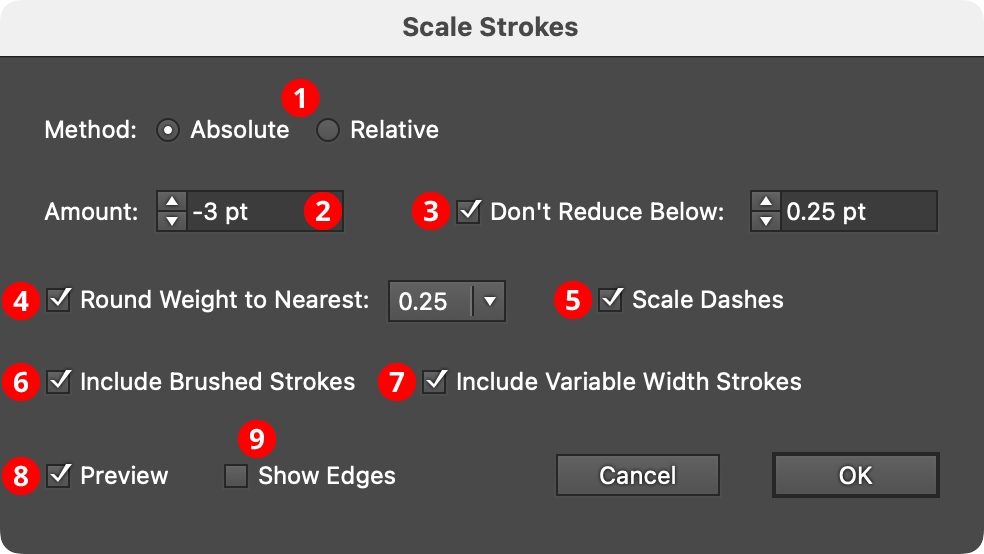
QuickOps Scale Strokes Settings
Note that stroke weight units are set independently from “general” units in Illustrator’s preferences dialog. Changing the unit of measurement for the document by right-clicking on a ruler will only change the general units, not the stroke weight units.
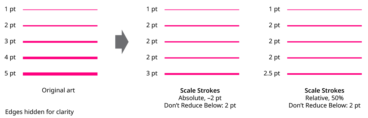
1. Method
With the Absolute method, each stroke weight is modified by adding a fixed amount to it; this amount can be positive or negative. Weights that end up at 0 pt or less will result in the stroke being removed (unless the Don’t Reduce Below setting is used). With the Relative method, each stroke weight is modified by multiplying it by a specified percentage.
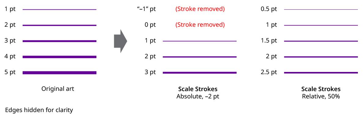
QuickOps Scale Strokes Absolute Vs. Relative
2. Amount
The amount to change the stroke weight(s), either as an absolute amount, like “–2 pt” or “3.5 mm”, or a relative amount, like 75%. Absolute amounts can range from –1000 to 1000 pt. Relative amounts can range from 0.01% to 10000%. When a negative absolute amount causes at least one stroke to end up with a weight of zero or less, and therefore be removed, a small warning icon will appear on the dialog.
While an Absolute value of zero (or a Relative value of 100%) does not directly change any stroke weights, it can still be useful when used with the Round Weights function (see below).
3. Don’t Reduce Below
When enabled, and the Absolute value is negative or the Relative value is less than 100%, strokes will never be made thinner than the specified value. Strokes that originally had weights below that minimum value will remain unchanged.
QuickOps Scale Strokes Don't Reduce Below
4. Round Weight to Nearest
When enabled, all stroke weights will be rounded to the nearest specified fraction, using the current stroke units of measurement. Available fractional rounding amounts are 1.0 (in other words, the nearest integer), 0.5, 0.25, 0.1, 0.05, and 0.01.
For example, a 2.38 mm stroke would be rounded down to 2 mm when the rounding fraction is 1.0, up to 2.5 mm when the rounding fraction is 0.5, and up to 2.4 mm when the rounding fraction is 0.1. Weights that would normally be rounded down to zero are instead rounded up. Similarly, if Don’t Reduce Below is enabled, and a weight would be rounded down below the threshold, then it is instead rounded up.
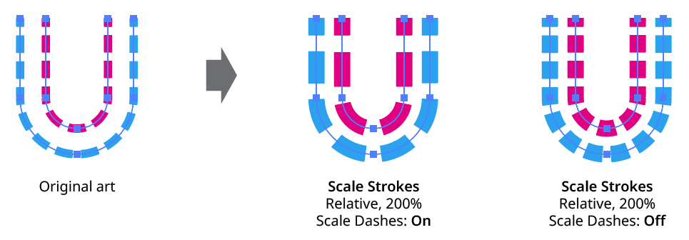
5. Scale Dashes
When enabled, dash and gap lengths are scaled up or down with the stroke.
QuickOps Scale Strokes Scale Dashes
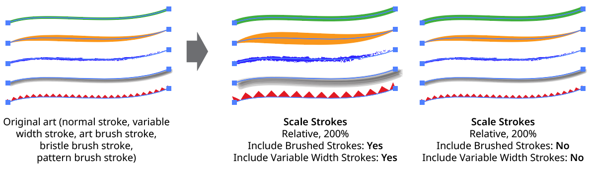
6. Include Brushed Strokes
The Include Brushed Strokes setting can be turned off to exclude strokes that have a brush applied from being scaled. This applies to all types of brushes (Calligraphic, Scatter, Art, Bristle, and Pattern).
7. Include Variable Width Strokes
The Include Variable Width Strokes setting can be turned off to exclude strokes that have a variable width profile applied from being scaled.
QuickOps Scale Strokes - Include Brushed and Variable Width Strokes
8. Preview
When Preview is enabled, the artwork’s new appearance with its scaled strokes is shown on the artboard, and will update whenever the settings are changed. Turning Preview off will show the artwork with its original stroke weights, allowing you to toggle to quickly see “before and after.”
9. Show Edges
By default, artwork selection edges are automatically hidden when the Scale Strokes settings dialog is up, to make it easier to see stroke weight changes. However, by toggling the checkbox on, they may be shown again.
Scale Strokes: Other Considerations
a. Strokes which are hidden in the Appearance panel are scaled as normal.
b. If an object contains multiple strokes, they are all scaled.
c. If some stroked items are grouped and a stroke is added at the group level, then when the entire group is selected, both the group-level stroke and the group member strokes are scaled.
d. If the type tool has been used to select some text, only the selected characters will be affected.
e. InkFlow strokes do not use the native stroke weight for their appearance, but can be scaled using the Live Effect Parameter Editor.
Make/Release Type On Path
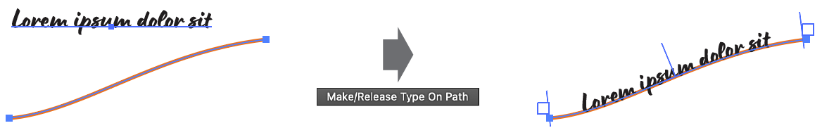
The Make/Release Type On Path operation performs two equal but opposite functions. First, it combines a selected point type object with a selected path object to create a type-on-a-path object, using the following criteria:
a. The path is not moved.
b. Any stroke or fill on the path is retained (unlike doing this natively by clicking on the path with the Type or Type on a Path tool).
c. The Type on a Path Options effect type is set to “Rainbow.”
d. The Type on a Path Options align type is set to “Baseline.”
e. The start and end markers are set to the start and end of the path.
QuickOps Make/Release Type on Path - Make
Second, if the selection consists of an existing type-on-a-path object, then that object is released back into its constituent parts (a point type object and a normal path). The point type is placed directly above the path object, centered on its bounding box. Overset text (if any) is retained.

QuickOps Make/Release Type on Path - Release
The Make/Release Type On Path operation can work on multiple objects simultaneously. When making multiple type-on-a-path objects, the point type objects and path objects are matched one by one using their stacking order to make pairs. In other words, the top-most type object is paired with the top-most path object, the next-lower type object is paired with the next-lower path object, and so on down the order, until one or both types of objects run out.
This ability to create multiple type-on-a-path objects with a single click makes possible some designs which would otherwise require an inordinate amount of manual copying and pasting (or custom scripting):
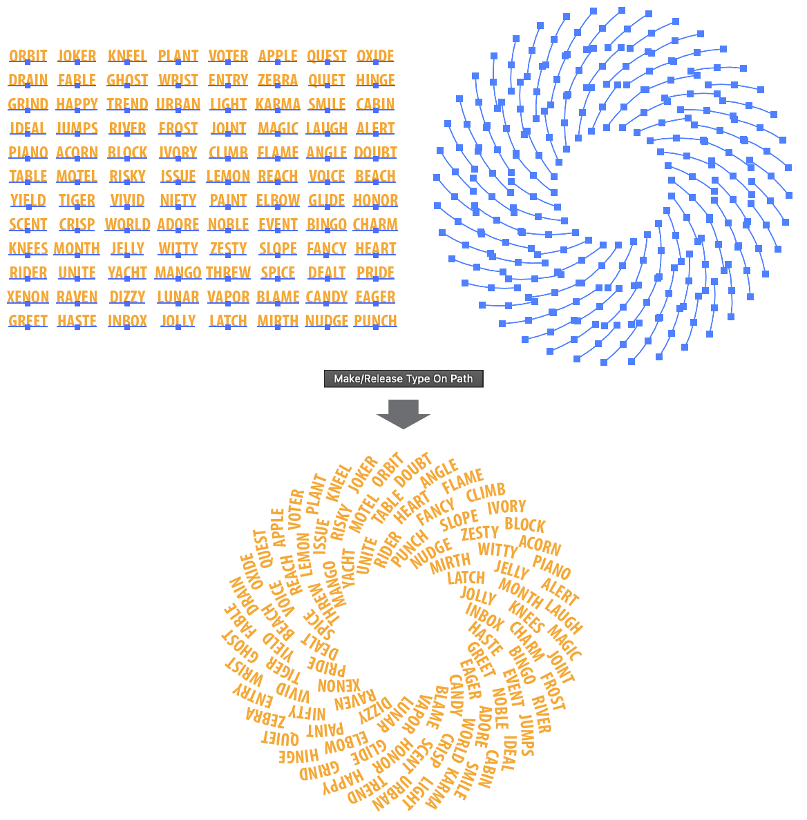
QuickOps Make/Release Type on Path - Multiple
Reduce Colors
The Reduce Colors operation reduces the number of colors used in strokes, fills, and (optionally) gradient stops by averaging and combining similar colors together. The resulting colors may be saved as regular swatches or as global swatches.
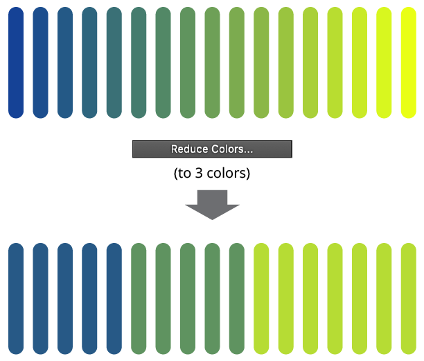
QuickOps Reduce Colors Overview
Clicking the button brings up the settings dialog:
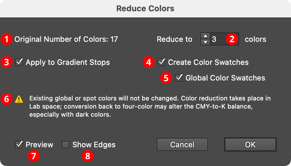
QuickOps Reduce Colors Settings
1. Original Number of Colors
Shows the original number of colors in the selected artwork which can be reduced. Reducible colors are the non-global, non-spot colors in strokes, fills, and (when Apply to Gradient Stops is enabled) gradient stops.
2. Color Count
The desired number of colors in the final artwork, from 1 to 1000. The value must be lower than the original number of colors.
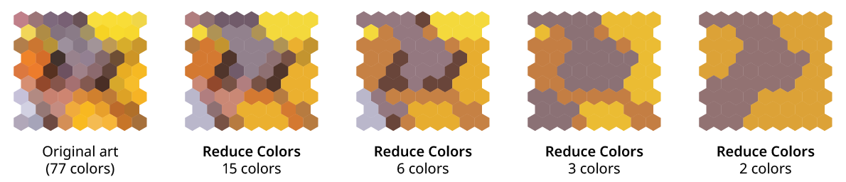
QuickOps Reduce Colors Examples
3. Apply to Gradient Stops
Available when there are linear or radial gradients in the selected artwork. When enabled, the reducible colors in the stops of each gradient are also affected. (Note that as with all gradients, there will still be additional intermediate colors created between the stops, if the stop colors are different).
4. Create Color Swatches
When enabled, new swatches are created for each of the reduced colors.
5. Global Color Swatches
Available when the Create Color Swatches setting is enabled. The Global Color Swatches setting makes each new swatch a global color, so that the artwork can be recolored more easily afterwards.
6. Warnings
Possible warning include:
Existing global or spot colors will not be changed. To affect these colors, use one of the native Edit > Edit Colors > Convert to... menu items to change them to CMYK or RGB first.
The selection contains colors in patterns, artwork types, or live effects which will not be changed. The Reduce Colors operation is meant only for flat colors and linear/radial gradients in strokes and fills. The colors used in gradient meshes, raster images, symbols, and so on will not be affected.
Color reduction takes place in Lab space; conversion back to four-color may alter the CMY-to-K balance, especially with dark colors. This warning is shown when reducing colors in a CMYK document.
7. Preview
When Preview is enabled, the artwork’s new appearance with the colors reduced is shown on the artboard, and will update whenever the settings are changed. Turning Preview off will show the artwork in its original state, allowing you to toggle to quickly see “before and after.”
8. Show Edges
By default, artwork selection edges are automatically hidden when the Reduce Colors settings dialog is up, to make it easier to see the color changes. However, by toggling the checkbox on, they may be shown again.
Delete Unused Panel Items
The Delete Unused Panel Items operation deletes, depending on its settings, unused items in the current document that are contained in one or more of the following native panels: Brushes, Graphic Styles, Swatches, and Symbols. When all four types of items are enabled, the operation is equivalent to using the default Action with the same name that ships with Illustrator (however, it runs more quickly than an Action).
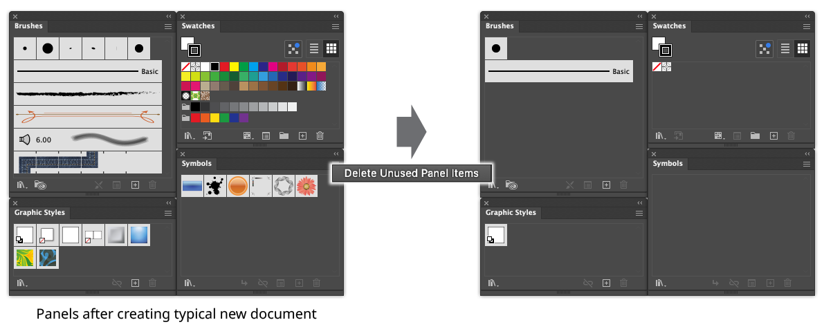
QuickOps Delete Unused Panel Items Example
Holding down Shift when clicking the button can operate on an alternate set of panels, if the settings are so configured. For example, the Swatches panel could be protected, while the Brushes, Graphic Styles, and Symbols panels are still affected.
To configure the settings, click the small icon to the right of the button, which will bring up the settings dialog:
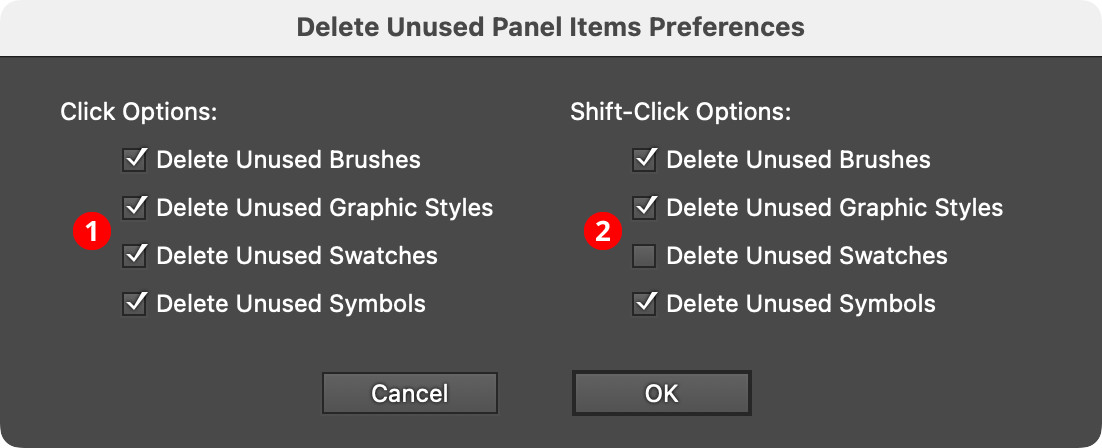
QuickOps Delete Unused Panel Items Preferences
1. Click Options
Specifies which unused items are deleted when the button is clicked with no modifier keys pressed.
2. Shift-Click Options
Specifies which unused items are deleted when the button is clicked with the Shift key pressed.
Rename Swatches
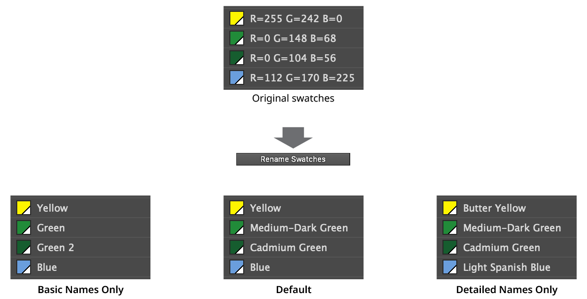
The Rename Swatches operation renames selected flat-color swatches (including global and spot colors) with human-friendly color names, using an internal database of over two thousand names.
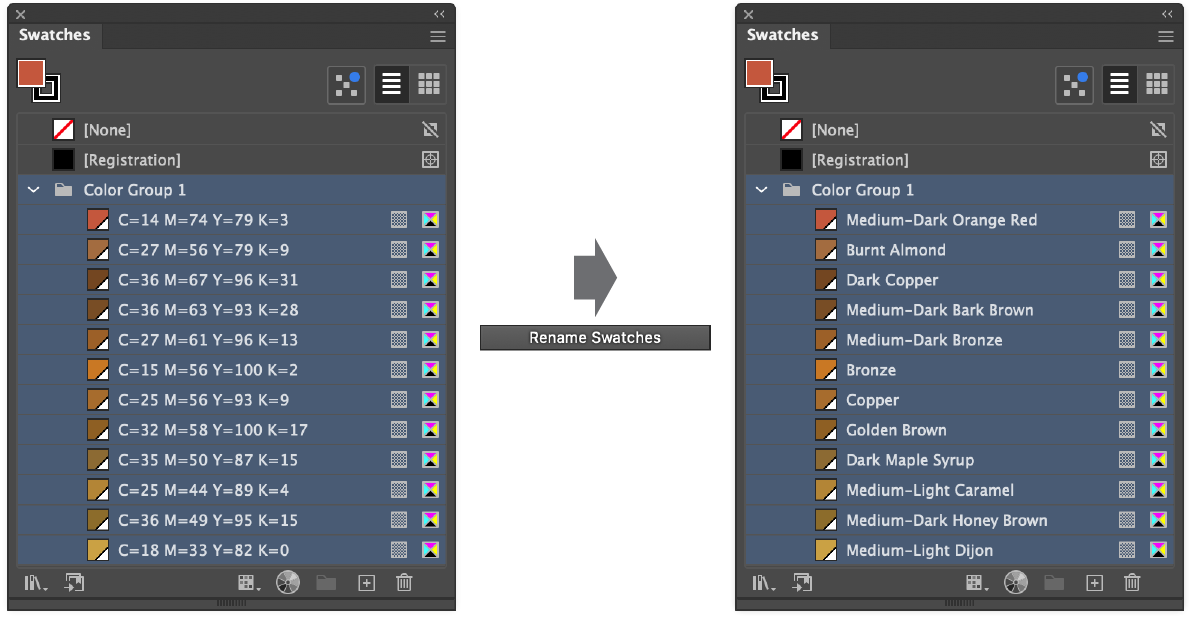
QuickOps Rename Swatches Example
Holding down Shift when clicking the button can use a different naming mode, if the settings are so configured. To configure the settings, click the small icon to the right of the button, which will bring up the settings dialog:
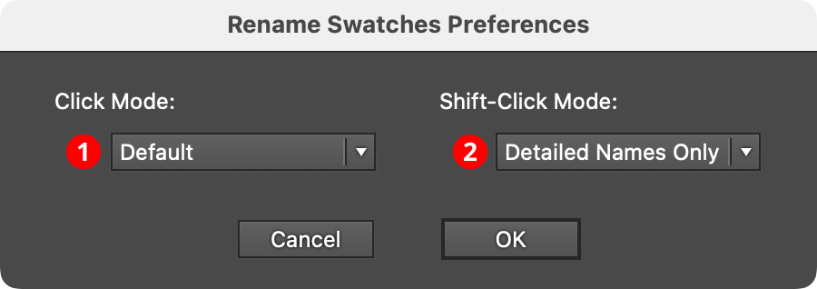
QuickOps Rename Swatches Preferences
1. Click Mode
Specifies which naming mode (see below) to use when the button is clicked with no modifier keys pressed.
2. Shift-Click Mode
Specifies which naming mode to use when the button is clicked with the Shift key pressed.
There are three different naming modes:
Basic Names Only: Only simple names like “Purple”, “Yellow”, and “Red-Orange” are used, possibly modified by “Light”, “Dark”, or “Dull”.
Default: Simple names are used, except when two or more colors would be given the same simple name, in which case more detailed names are used to distinguish them, such as “Canary Yellow” and “Cobalt Yellow”.
Detailed Names Only: Detailed names are always used.
In all modes, if two colors are so similar that they would be given the same name, then integers are appended as needed to distinguish them, for example “Candy Pink” and “Candy Pink 2”.
QuickOps Rename Swatches Naming Modes
Group By Proximity
The Group By Proximity operation takes the selected art objects and makes separate groups of those that are close to each other. Grouping is previewed, and the tolerance value adjusts how close objects must be to each other to be grouped.
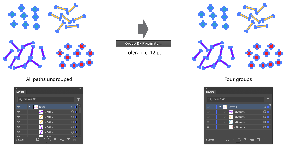
QuickOps Group by Proximity Example
Clicking the button when there are at least two art objects selected brings up the settings dialog:
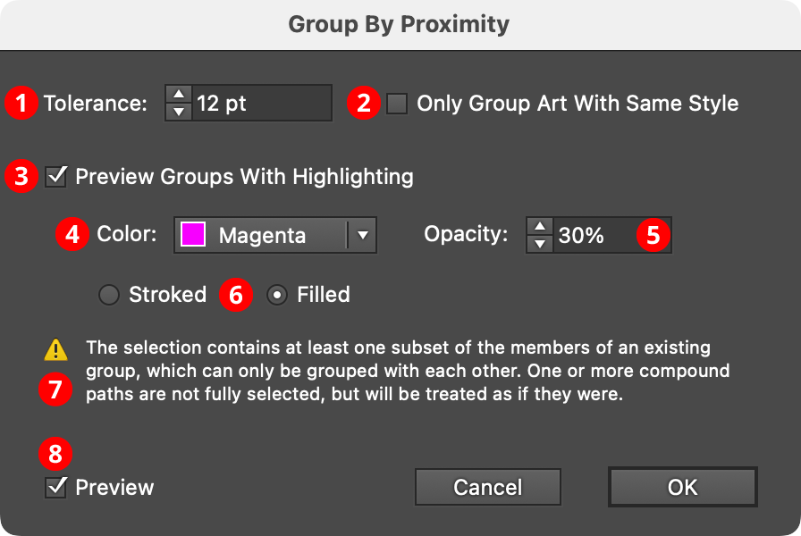
QuickOps Group by Proximity Settings
1. Tolerance
Specifies the approximate distance between two pieces of art below which they will be grouped, from –1000 pt to 1000 pt. Negative values indicate that the objects must overlap by at least that much. For performance reasons, Group By Proximity uses the Tightest Bounds for each art object when determining the distances between them. The Tightest Bounds is the smallest rectangle that fits around the object, when allowed to rotate freely (i.e., unlike a standard bounding box, it does not have to be orthogonally-aligned to the X- and Y-axes). This may cause objects which don’t visually touch to be considered as touching, even with a tolerance of zero.
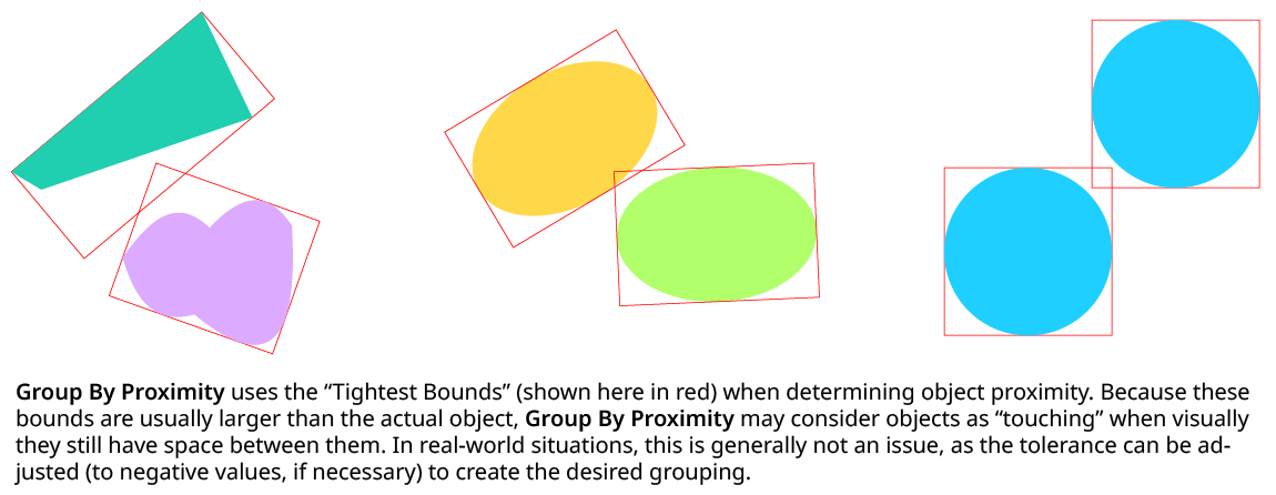
QuickOps Group by Proximity Tightest Bounds
2. Only Group Art With Same Style
When enabled, art objects with different styles will never be grouped, regardless of tolerance value. The style of a group which has no stroke, fill, or group-level effects is taken to be the style of its members, as long as they are all identical.
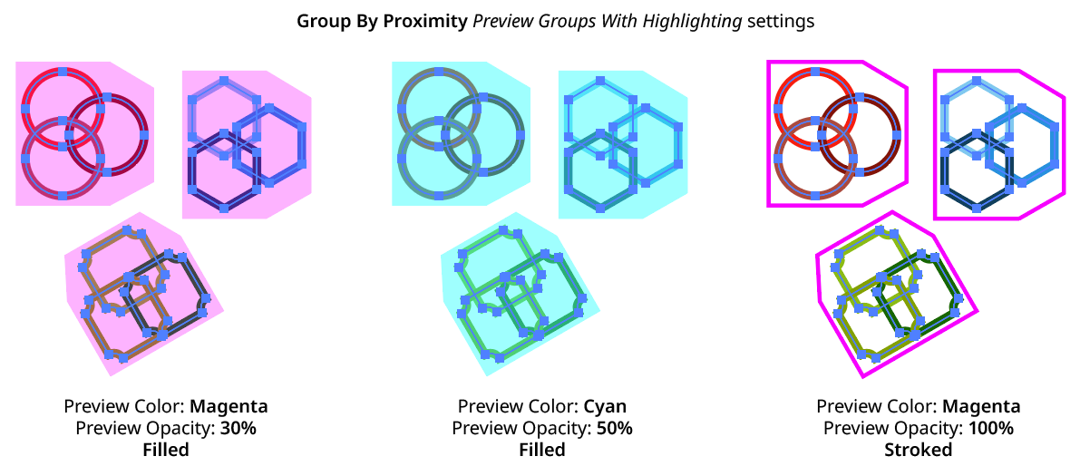
3. Preview Groups With Highlighting
Because there is usually no visual difference between ungrouped and grouped artwork, by default Group By Proximity draws highlighting polygons over each new group that will be created while the settings dialog is open. The style of the highlighting is controlled by the additional controls underneath.
4. Preview Color
Specifies the color of the preview highlighting, from among Red, Blue, Magenta, Green, Yellow, and Cyan.
5. Preview Opacity
Specifies the opacity of the preview highlighting (by default, 30%).
6. Stroked/Filled
Specifies whether the preview highlighting consists of filled polygons or stroked polygons.
QuickOps Group by Proximity Previewing
7. Warnings
The warning icon and text appear if one or both of the following situations occur:
1. The selected art consists of some of the members of an existing group, but not the whole group. In this case, those members could only form new groups with each other (making nested groups), but not externally.
2. The selected art consists of some of the subpaths of a compound path, but not the whole compound path. In this case, the compound path will be treated as if it were fully selected.
8. Preview
When Preview is enabled, the artwork’s new grouping is shown on the artboard (unless Preview Groups With Highlighting is turned off), and will update whenever the settings are changed. Turning Preview off will show the artwork in its original state, allowing you to toggle to quickly see “before and after.”
QuickOps Panel Flyout Menu
QuickOps Panel Flyout Menu
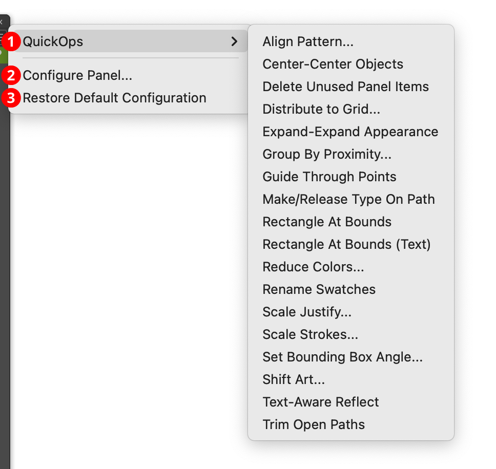
1. QuickOps
Provides access to all of the QuickOps operations, which are listed in alphabetical order. This is mainly useful for accessing a lesser-used operation whose button has been hidden from the panel. As with the buttons, Shift may be held when selecting the menu item to get the operation’s alternate mode.
2. Configure Panel...
Allows the buttons on the QuickOps panel to be configured to your liking. Removing QuickOps that you never use will make the panel smaller and less cluttered. Choosing the menu item will bring up the panel configuration dialog:
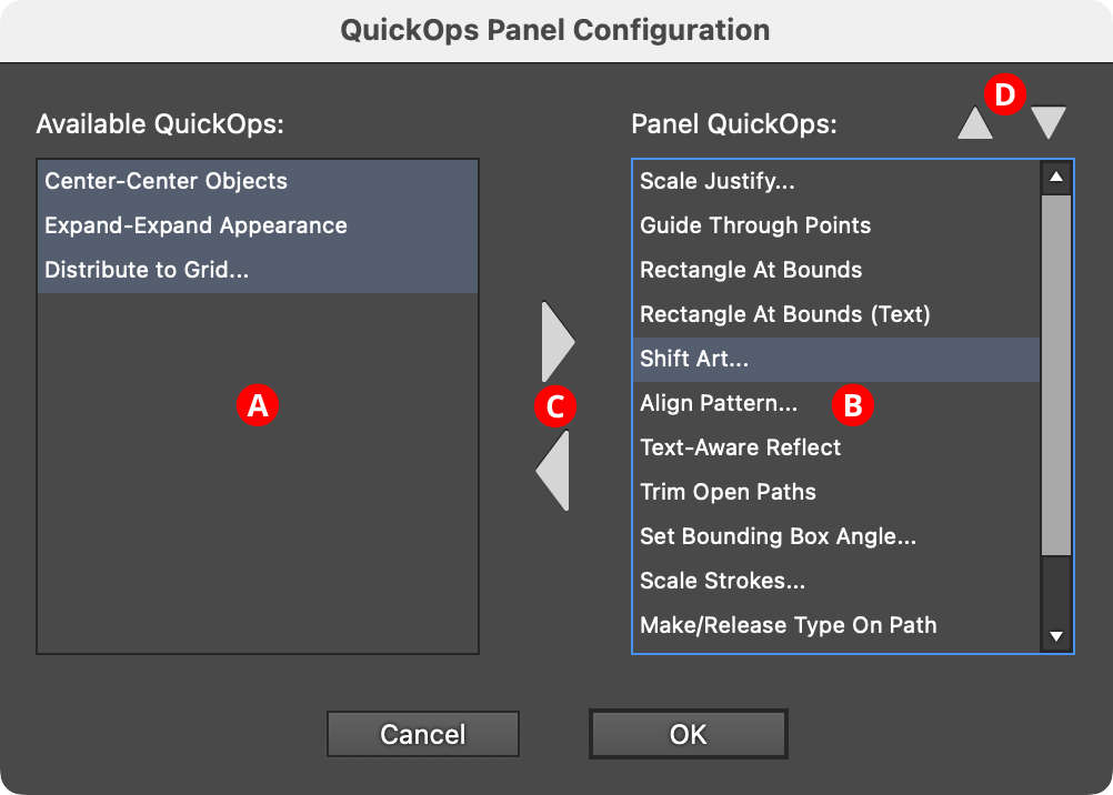
QuickOps Panel Configuration
A. Available QuickOps List: The QuickOps that can be added to the panel QuickOps, from among all possible QuickOps. Multiple QuickOps can be selected by using
ShiftorCommand/Ctrl, as usual.B. Panel QuickOps: The QuickOps that will have buttons on the panel.
C. Add/Remove Buttons: These buttons move one or more selected QuickOps into or out of the panel. The panel list must contain at least one QuickOp.
D. Move Up/Move Down Buttons: Move the selected QuickOp(s) upwards or downwards in the panel list, thereby changing the order of the buttons.
3. Restore Default Configuration
Re-configures the panel to its default configuration, with all buttons visible and in the default order.
Actionability
All of the QuickOps may be recorded and played back as actions, except the two that use an interactive tool (Shift Art and Align Pattern).