 AG Architect Panel
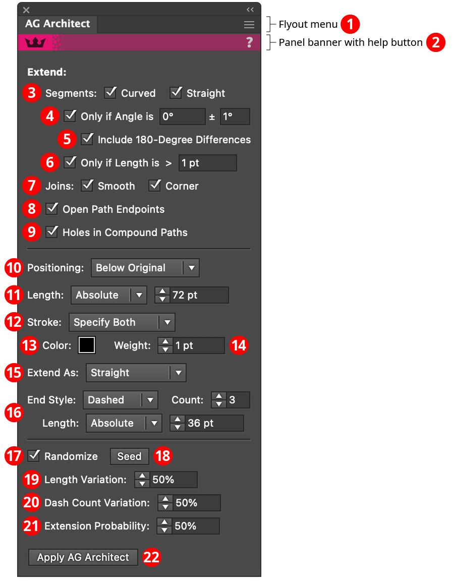
The AG Architect live effect does not have a modal parameters dialog, but is instead edited using a panel, which can be shown and hidden using the menu item found in the main menu at Window > Astute Graphics > AG Architect. When at least one selected object has the AG Architect live effect applied, the panel controls will update to reflect the parameters of those effects, which can then be edited. A value field which is blank or (for checkboxes) with a dash indicates that the parameter has different values in the selection. These can be unified (made the same) by entering a new value.
AG Architect Panel
1. Flyout menu
See AG Architect Panel: Flyout Menu.
2. Panel banner
The help button on the right opens the help documentation in the Astute Manager. If this does not automatically appear, please ensure your Astute Manager is running first.
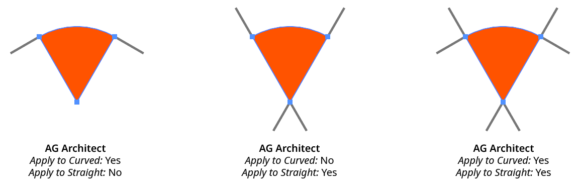
3. Segments
Extension lines will be added to path segments which are curved and/or straight, when the corresponding option is enabled.
AG Architect Curved Straight Example
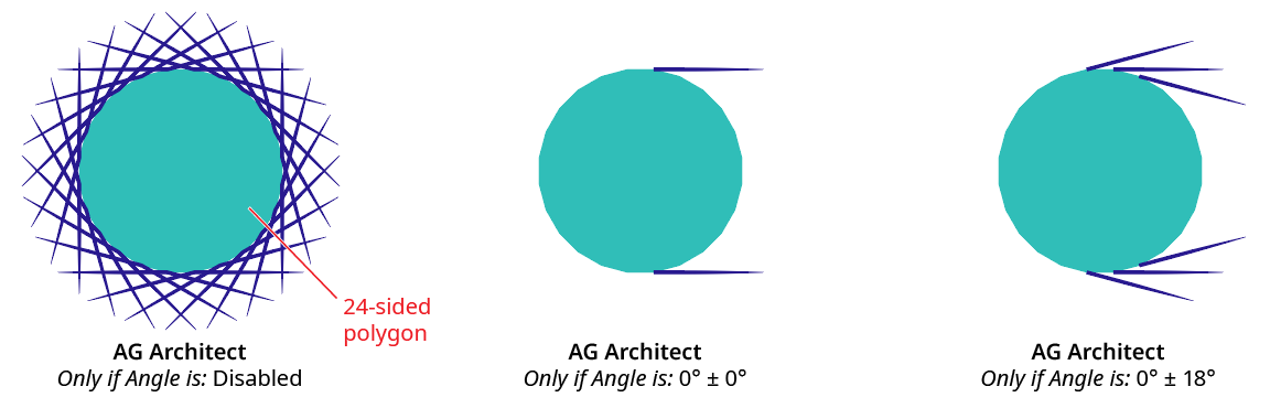
4. Only If Angle Is
When enabled, extension lines are only added if their angle matches the specified value (within the specified tolerance). Angles are measured using the normal Illustrator convention.
AG Architect Only if Angle is Example
5. Include 180-Degree Differences
When using the Only if Angle is setting, specifies that directions 180° from the specified angle should be considered the same.

AG Architect 180 Degree Difference Example
6. Only If Length is
When enabled, extension lines are only added to path segments that are longer than the specified length.
7. Joins
Extension lines will be applied at the ends of path segments which end in smooth or corner anchor points, when the corresponding option is enabled.
8. Open Path Endpoints
Extension lines will be added at the ends of open paths.
9. Holes in Compound Paths
Extension lines will be applied to path segments which comprise subpaths which form holes in compound paths.
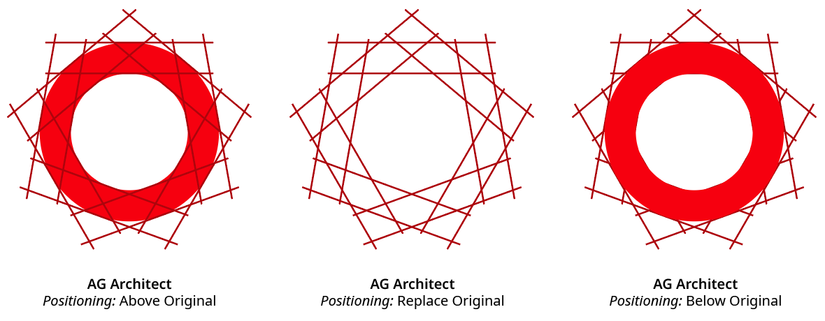
10. Positioning
The stacking position of the extension lines relative to the original source art, from among Above Original, Replace Original, or Below Original.
AG Architect Positioning Example
11. Length
The base length of the extension lines (before any randomization). When the dropdown menu is set to Absolute, the length is specified as an absolute value (for example, 15 pt). When the dropdown men is set to Relative, the length is specified as a percentage of the diagonal length of the source path’s bounding box.
12. Stroke
The stroke style of the extension lines, as specified using the dropdown menu. When set to Use Original, the stroke’s style is taken from the original source path (except dashes are not preserved). Otherwise, the color, weight, or both is set to the specified values.
13. Color
Available when the stroke is set to Specify Color or Specify Both; specifies the color of the extension lines. Clicking the color chip brings up a standard color picker dialog.
14. Weight
Available when the stroke is set to Specify Weight or Specify Both; specifies the stroke weight of the extension lines.
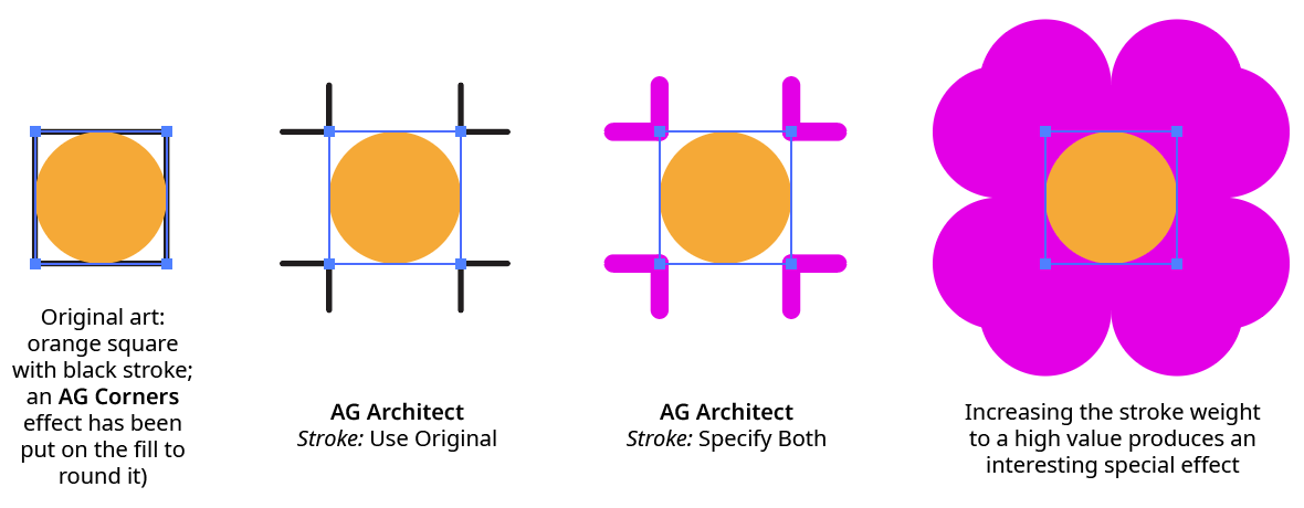
AG Architect Stroke Example
15. Extend As
Specifies the extension’s geometry, either Straight (all extension lines are straight) or Smooth Curve (extensions from curved path segments will also be curved, following the natural extension of the bezier curve’s shape).
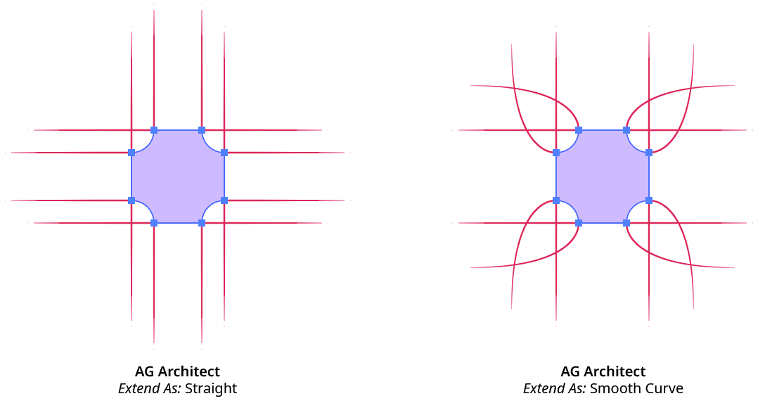
AG Architect Extend As Example
16. End Style
Specifies the style for the terminus of the extension lines.
Normal extension line end without any special treatment; the end cap type is either taken from the stroke on the original path (if the Stroke setting is set to Use Original or Specify Color), else is set to Butt Cap type.
Tapered extension line thin to a sharp point. The length of the tapered portion of the line can be specified either as an absolute distance or as a percentage of the total line length. When AG Architect effects with Tapered extension lines are expanded, the lines are converted into closed path shapes.
Dashed extension line end in one or more dashes, which shorten towards the end of the line. The number of dashes can be changed (from 1 to 9), and the length of the dashed portion of the line can be specified either as an absolute distance or as a percentage of the total line length.
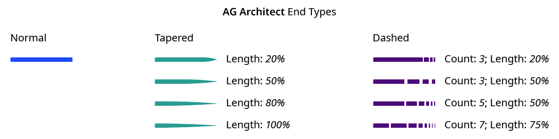
AG Architect End Styles
17. Randomize
When enabled, several of the live effect’s parameters can be randomly varied: the length of the extensions, the dash count (if Dashed end type is used), and the probability that an extension line will be created at all.
18. Seed
Each random seed number leads to a different sequence of random values. Clicking the button picks a new seed, thereby changing the look of the artwork. To view or specify the seed number directly, Option/Alt-click the button. This lets you recreate a previously-generated look.
19. Length Variation
When randomization is enabled, specifies the maximum amount of variation in the final extension line length. For example, if the length is set to 20 pt, then a variation value of 25% would produce lengths that vary by as much as 20 pt × 25% = 5 pt, that is, between 15 pt and 20 pt; a variation value of 90% would produce lengths between 2 pt and 20 pt.
20. Dash Count Variation
When randomization is enabled, specifies the random variation in the dash count (when using the Dashed end type). For example, if the count is set to 8, then a variation value of 25% would produce count values that vary by as much as 8 × 25% = 2, that is, either 7 or 8; a variation value of 100% would produce count values between 1 and 8.
21. Retention Probability
When randomization is enabled, specifies the probability that an extension line will be created at each spot where one is eligible.
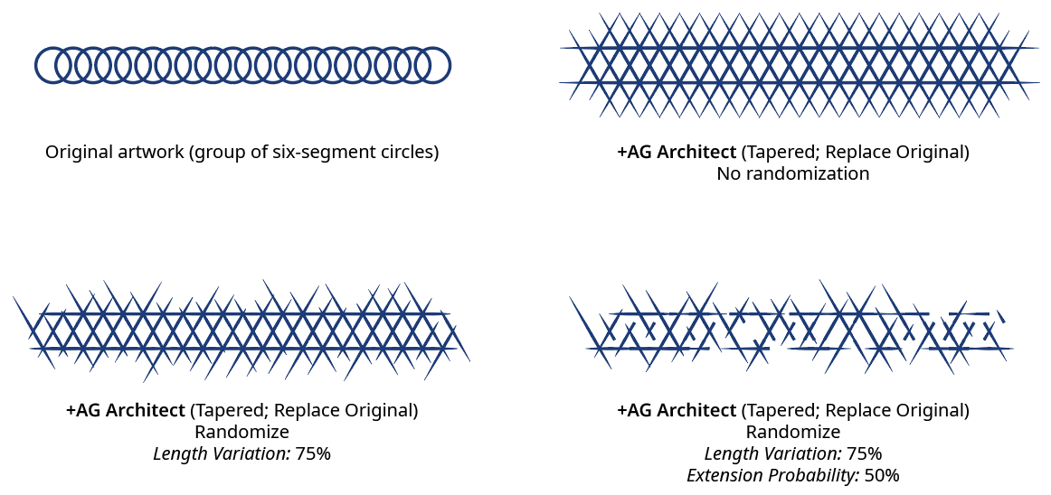
AG Architect Randomization
22. Apply Button
Click to apply the AG Architect live effect to the selected artwork, with the parameters set as they currently exist in the panel. If the button is not available, then either nothing is selected or the selection already contains at least one object with an AG Architect effect. If the button is clicked with Shift pressed, the extension lines will be added and immediately detached, essentially creating them as editable artwork rather than as a live effect. However, this loses the ability to preview the effect first.
AG Architect Panel Flyout Menu
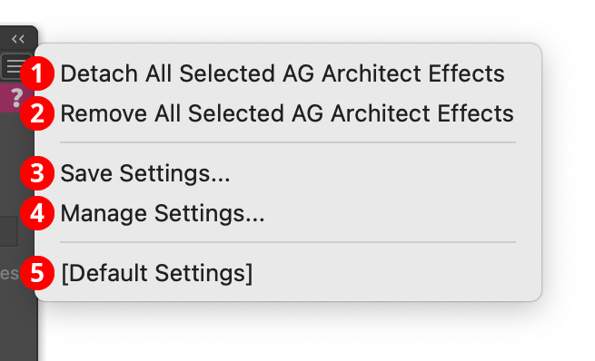
The AG Architect panel flyout menu items are contextually sensitive and all items may not be available, depending on the current selection.
AG Architect Panel Flyout Menu
1. Detach All Selected AG Architect Effects
Changes the extension lines created by all AG Architect live effects in the selection into editable artwork, and removes the effect from the appearance(s). This is similar to using the native menu command Object > Expand Appearance, but is more flexible because it leaves the existing artwork (and other live effects which may be present) intact.
2. Remove All Selected AG Architect Effects
Removes any AG Architect live effects from the selection. (This can be done from the Appearance panel as well, but not if multiple AG Architect effects are present with different parameters. In that case, the Appearance panel will simply display “Mixed Appearances” and the ability to select the live effect and delete it will no longer be available.)
3. Save Settings...
Captures all of the current parameter settings on the panel to a file, which can be instantly recalled later (either in the current file session or a later one). A dialog will appear through which the file name may be specified.
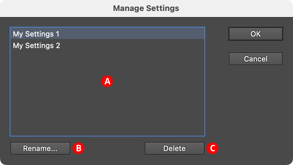
4. Manage Settings...
Brings up a dialog through which existing settings files may be renamed or deleted:
AG Architect Manage Settings Dialog
A. Settings List: Shows all user-saved settings. One or more settings files can be selected for use with the buttons at the bottom of the dialog by clicking on them in the list, with Shift pressed to select contiguously or Command/Ctrl pressed to select discontiguously, as normal.
B. Rename Button: If a single settings file is selected, allows it to be renamed, through a separate dialog. If the Cancel button is used, the original names will be restored.
C. Delete Button: Removes the selected settings file(s). The files are not permanently deleted until the OK button is clicked.
5. Settings Files
User-defined settings will appear below the built-in [Default Settings] menu item. Choosing a settings menu item will load the panel with the settings it had when the file was saved; the AG Architect effects in any selected art will be updated to match.