 Rotate Section
The Rotate section of the dialog has the following controls:
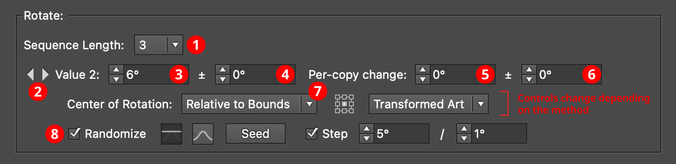
AG Transform Parameters Dialog, Rotate Section
1. Rotation Sequence Length
By default (and ignoring randomization), each copy receives the same rotation value (as with the native Transform effect). However, AG Transform offers sequences, which allow up to 8 different rotation values. If the number of copies exceeds the length of the sequence, the values simply repeat in a cycle. Each member of a sequence shares the same randomization parameters.
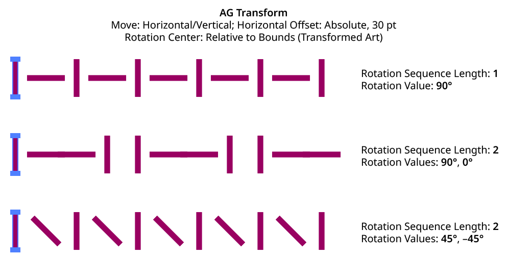
AG Transform Rotation Sequence Examples
2. Previous/Next Offset Buttons
Available when the sequence length is set to a value other than 1. Clicking either button will move between the sequence’s values, allowing any of them to be edited.
3. Value/Base Value
The angular value for the current sequence index. When randomization is enabled, this value specifies the base angle to which a random amount is added or subtracted.
4. Base Value Variation
Available when randomization is enabled; it is the maximum angular value which is added to or subtracted from the base value to get the random value. For example, if the base value is set to 45°, and the random variation is set to 10°, then angles from 35° to 55° may be produced.
5. Per-copy Change Value
The angular amount to add to the base value for each new copy. For example, if the base value is set to 20°, and the per-copy change is set to 3°, then the first copy will be rotated 20°, the second at 23°, the third at 26°, and so on.
6. Per-copy Change Value Variation
Available when randomization is enabled; it is the maximum angular amount which is added to or subtracted from the per-copy change value to get the random value.
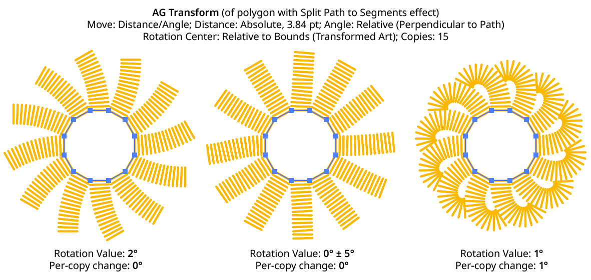
AG Transform Rotation Examples
7. Center of Rotation
The dropdown menu allows the choice between six different methods of specifying the center of rotation: Fixed, Relative to Bounds, Anchor Point, Position Along Path, Tagged Path, or Along Line.
Fixed: With this method, the center of rotation is simply specified by its coordinates.

AG Transform Center of Rotation Fixed Controls
This could be used to make multiple objects rotate around a common center, even if their position is subsequently adjusted:
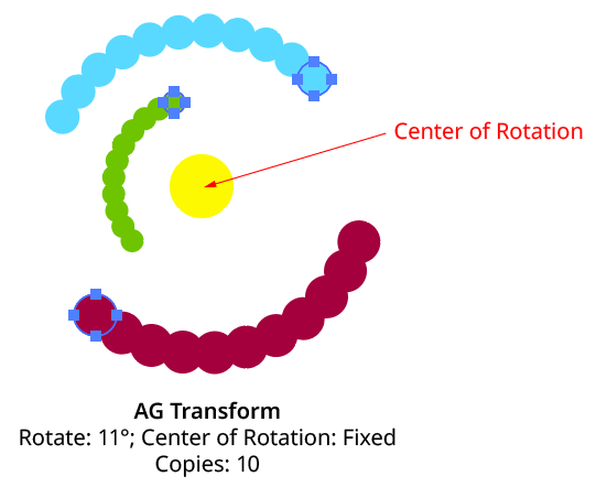
AG Transform Rotate Center Fixed
Relative to Bounds: This method (when used with Top-Level Art) is what the native Transform effect uses.

AG Transform Center of Rotation Relative to Bounds Controls
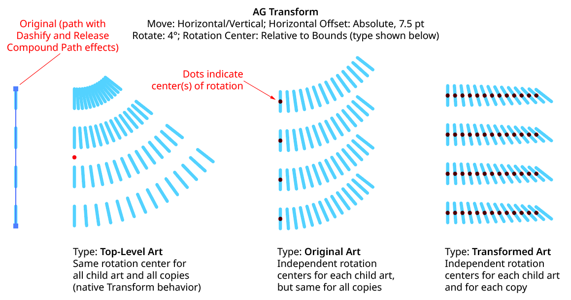
With this method, the center of rotation is located relative to the bounds of the specified art, using the standard nine-box control. The choices for the art type are Top-Level Art, Original Art, or Transformed Art. Top-Level Art is the art to which the AG Transform effect was applied (which may be a group). Original Art is the art at the specified Grouping Level which is being independently transformed, using its initial position for all copies. Transformed Art also refers to this art, but uses the transformed bounds for each copy, i.e., the center of rotation moves along with the copies.
To understand how changing the rotation center’s art type affects the results, it is helpful to understand the order of transform operations. For example, applying a native Transform effect with both a horizontal move and a rotation results in the left-hand image below and not the right-hand one — but why?
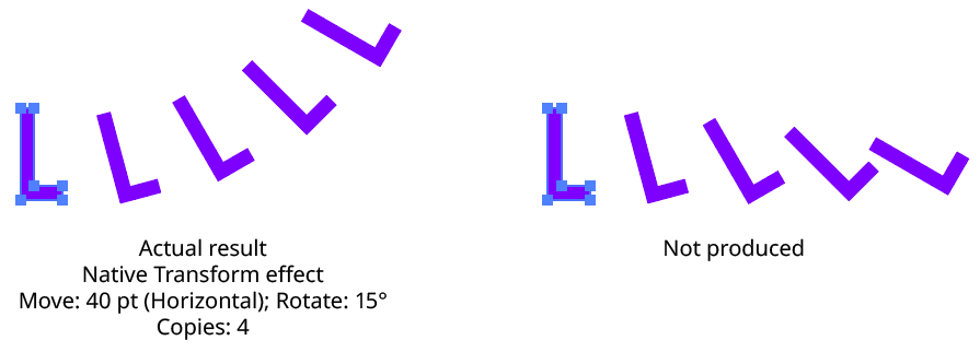
Native Transform Move Plus Rotate Example
The answer is due to two factors: the order of the transform operations, and the method of locating the center of rotation for each copy. For both the native Transform effect and AG Transform, each copy of the art is first scaled, then rotated, and finally moved (offset). The native Transform effect locates the center of rotation using the bounding box of the original art, and that center is used for all subsequent copies. Thus, the transform could be manually created as follows: Starting with the original art, a copy is made in place which is then rotated 15° around the center of rotation (the bounding box center). Then it is offset 40 pt to the right.
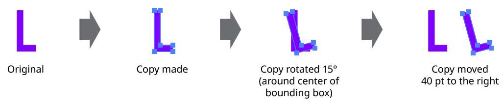
Native Transform Move Plus Rotate Manual Creation
This process is repeated for the second copy. Importantly, the center of rotation remains located at the center of the bounding box of the original art.
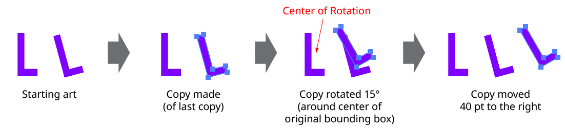
Native Transform Move Plus Rotate Manual Creation with Multiple Copies
The same steps are followed for each subsequent copy, which leads to the results shown originally.
AG Transform can be made to act like the native Transform effect for rotation by setting the Center of Rotation method to Relative to Bounds and the art type to Top-Level Art. However, the other two art types offer additional options:
AG Transform Rotate Center Relative to Bounds Examples
Anchor Point: With this method, the center of rotation is located at the specified anchor point of the art at the specified grouping level. The rotation point is transformed for each copy, along with the art. If the art does not contain a path, the Relative to Bounds method will be used instead.

AG Transform Center of Rotation Anchor Point Controls
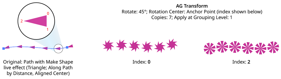
AG Transform Rotate Center Anchor Point Examples
Position Along Path: With this method, the center of rotation is located along the path of the art (from 0% to 100%) at the specified grouping level. The rotation point is transformed for each copy, along with the art. If the art does not contain a path, the Relative to Bounds method will be used instead.

AG Transform Center of Rotation Position Along Path Controls
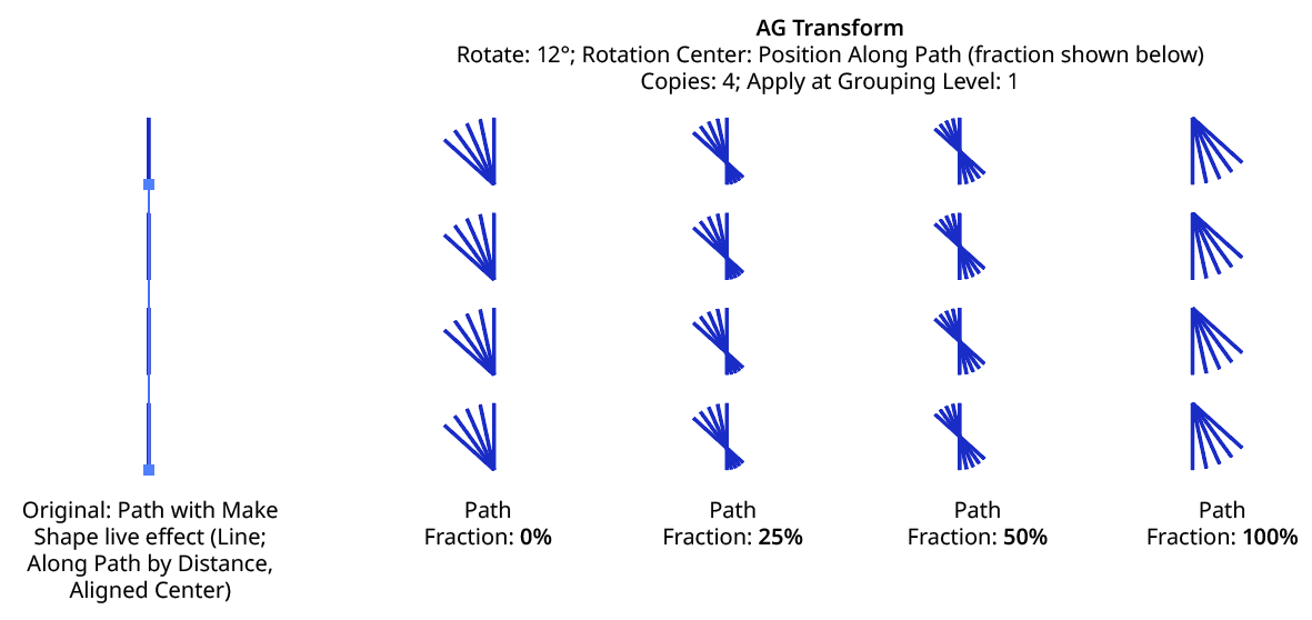
AG Transform Rotate Center Position Along Path Examples
Tagged Path: With this method, the center of rotation is located at the first anchor point of a path contained in the top-level group that has the note “AGTransformRotatePath” (as entered on the native Attributes panel). It is customary to use a single-point path for this purpose, so the path won’t inadvertently be made visible. If no such path exists, AG Transform uses the first path it finds in the top-level art. If no paths at all exist, the Relative to Bounds method will be used instead.

AG Transform Center of Rotation Tagged Path Controls
Along Line: With this method, the center of rotation is located along an imaginary line that passes through two points which are located using anchor point indices and t-values in the path art at the specified grouping level. The rotation point is transformed for each copy, along with the art. If the art does not contain a path, the Relative to Bounds method will be used instead.

AG Transform Rotate Center Along Line Controls
A. Start Index: The index of the anchor point used to locate the start of the imaginary line.
B. Start T-Val: The t-value (bezier-derived distance between the anchor point and the next anchor point, ranging from 0 to 1) of the start point.
C. End Index: The index of the anchor point used to locate the end of the imaginary line.
D. End T-Val: The t-value (bezier-derived distance between the anchor point and the next anchor point, ranging from 0 to 1) of the end point.
E. Fraction: The position of the center of rotation, as a fraction of the distance between the start point of the imaginary line and the end point. Values between 0% and 100% would put this point between the start and end, but the value can also be negative or greater than 100% to put the point outside this interval.
The Along Line method is similar to the Relative to Bounds method in that the center of rotation is always relative to the artwork. However, while Relative to Bounds only offers nine distinct positions, Along Line can specify an infinite number of such positions.
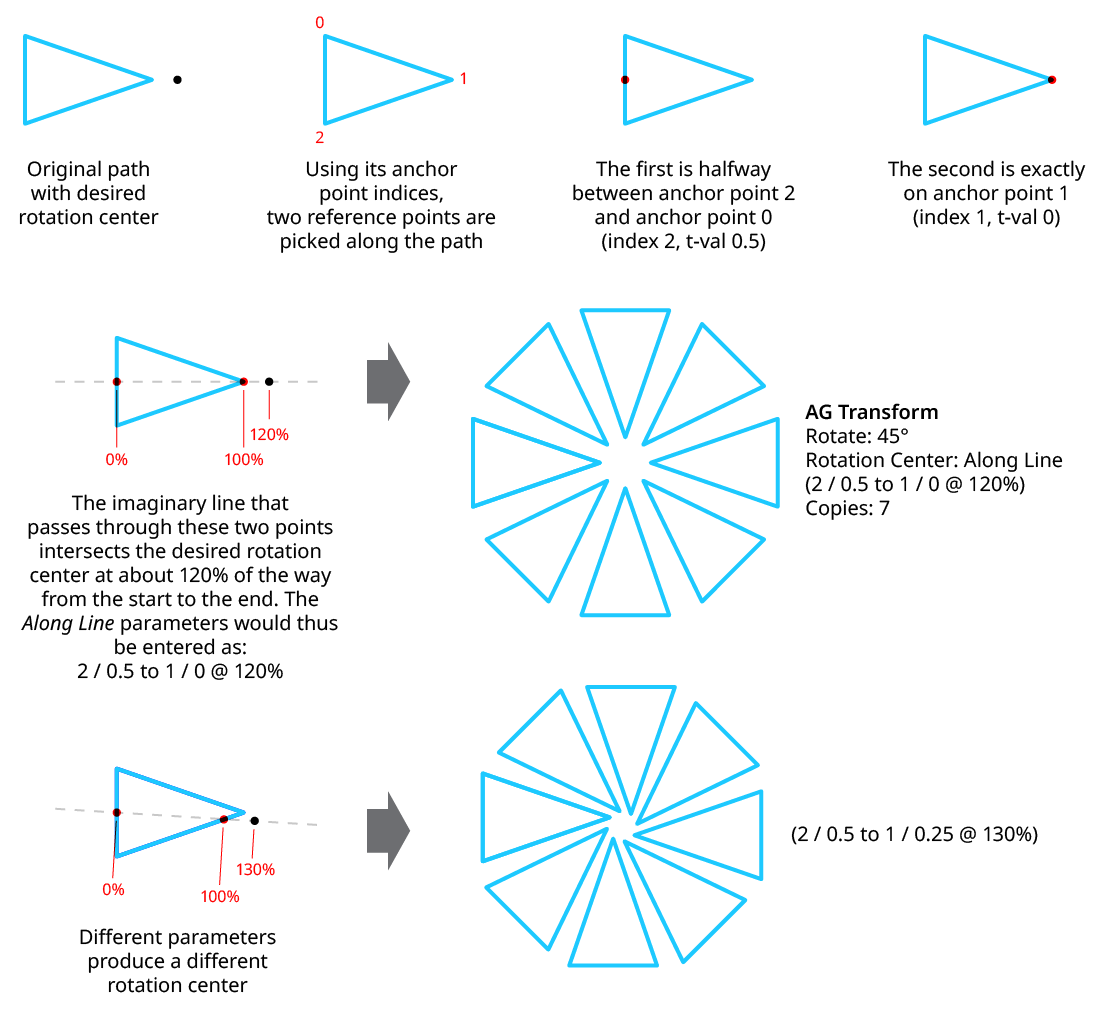
AG Transform Rotate Center Along Line Examples
8. Randomize
Randomization works the same way in the Rotate section of the dialog as it does in the Angle area of the Move section (when in Distance/Angle mode). Step values can be set for both the regular rotation value and for the per-copy change value.