 AG Transform Live Effect
AG Transform is a powerful Astute Graphics live effect that greatly expands upon the native Transform effect by adding features such as the ability to affect different grouping levels of the art, the option to move by distance and angle instead of simply by X- and Y-coordinates, sequences with separate parameters, additional options for specifying the centers of scaling and rotation, the ability to change the stacking order, filtering for only affecting a subset of multiple objects, and more.
As with most live effects, AG Transform appears in the main menu, under Effect > AG Utilities. It can also be applied directly from the Appearance panel using the “Add New Effect” button at the bottom of the panel.
AG Transform Parameters Dialog
After applying the live effect using the menu item (or when clicking on the existing effect in the Appearance panel to edit it), the parameters dialog will appear. The dialog is large, and is described by section:
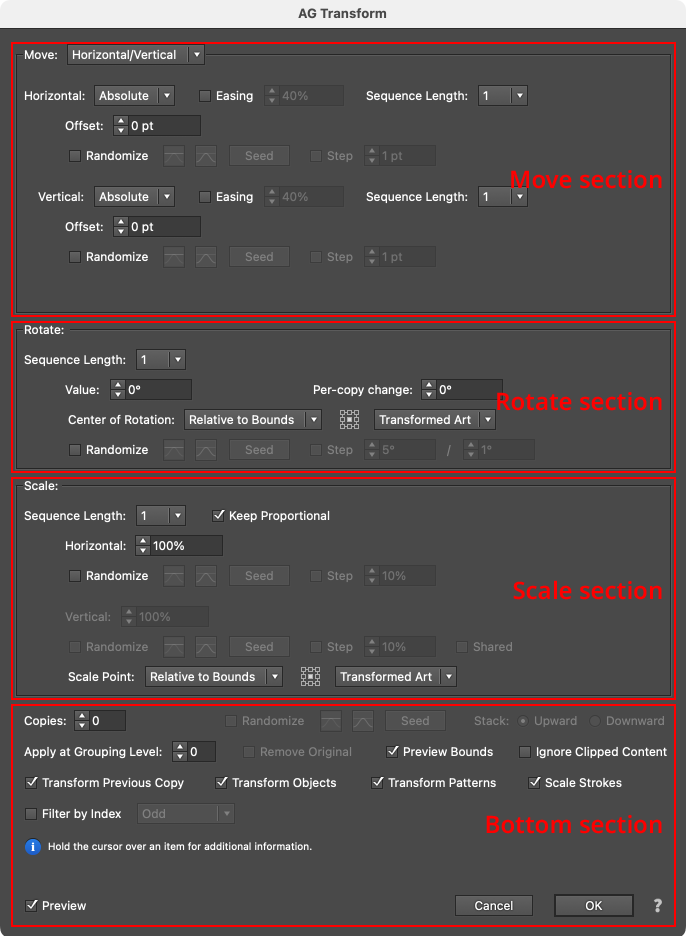
AG Transform Parameters Dialog Sections
Although the Move, Rotate and Scale sections are stacked in that order on the panel, the operations are actually performed in the reverse order. In other words, to transform the art, it is first scaled, then rotated, and finally moved. This is consistent with the native Transform effect’s order of operations.
Move Section: Horizontal/Vertical
Moving (offsetting) can be done in two main modes: Horizontal/Vertical (as with the native Transform, in which the offset is specified by its horizontal and vertical components) or Distance/Angle, in which the offset is specified by its distance and angle components. The main mode is controlled by a dropdown menu at the top of the Move section. In Horizontal/Vertical mode, the move section of the dialog has the following controls:
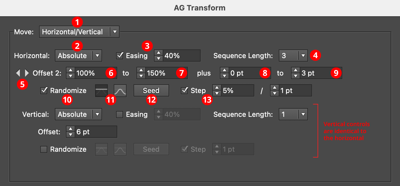
AG Transform Parameters Dialog: Move Section (Horizontal, Vertical)
1. Main Mode
The dropdown menu allows the choice between Horizontal/Vertical mode and Distance/Angle mode.
2. Horizontal/Vertical Submode
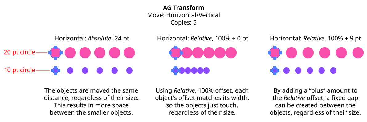
In Horizontal/Vertical mode, the dropdown menu allows the choice between Absolute or Relative submodes for both the horizontal and vertical components of the offset. In Absolute submode, each offset component is specified using an absolute value, such as 12 pt. In Relative submode, each offset component is specified using a percentage of the width (or height, for the vertical component) of the art’s bounding box, plus an optional non-relative value. Thus, when the submode is set to Relative and the offset is set to 100%, the “plus” value controls the gap between objects when multiple copies are made:
AG Transform Move Absolute Vs. Relative
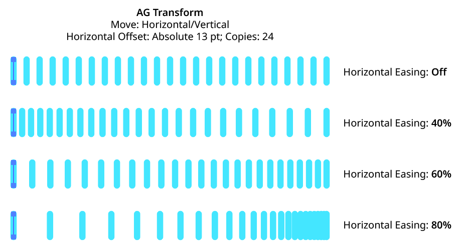
3. Horizontal/Vertical Easing
Easing controls the final spacing (either in the horizontal or vertical direction) of all of the transformed copies. When enabled, the easing value (from 1% to 99%) specifies where the middle copy should be placed (as a percentage of the distance from the original to the last copy). It therefore determines whether the copies increase their spacing as they get further away from the original (for values less than 50%), or decrease their spacing (for values more than 50%).
AG Transform Easing Examples 1
Easing can be used with both sequences and randomization. If the offsetting causes the copies to be created both to the left and right of the original, then the easing is done separately for each side.
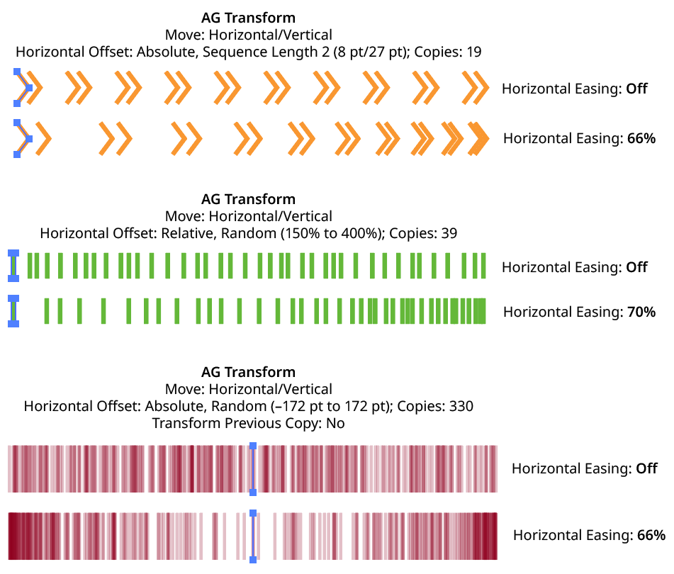
AG Transform Easing Examples 2
Using a different easing value for the horizontal and vertical components of the offset causes the trail of copies to move in a curve:
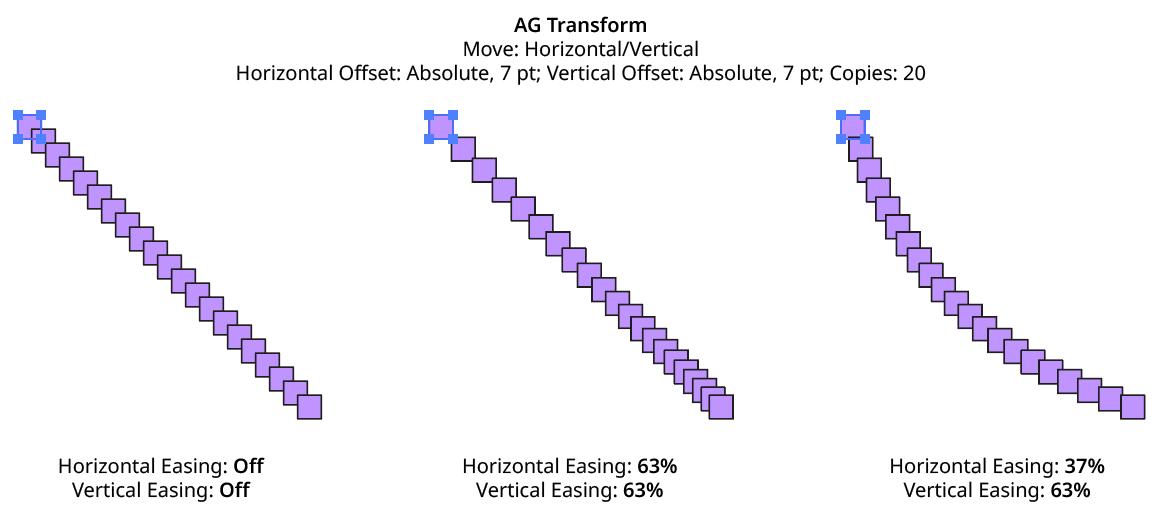
AG Transform Easing Examples 3
4. Horizontal/Vertical Sequence Length
By default (and ignoring randomization), each copy receives the same offset (as with the native Transform effect). However, AG Transform offers sequences, which allow up to 8 different offsets. The horizontal component of the offset can have a different sequence length from the vertical. If the number of copies exceeds the length of the sequence, the values simply repeat in a cycle. Each member of a sequence shares the same randomization parameters.
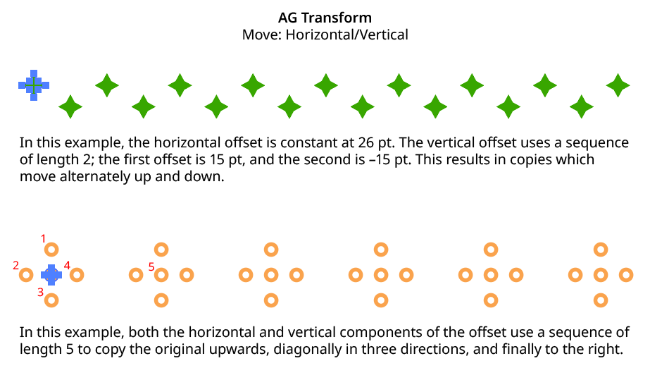
AG Transform Horizontal Vertical Sequence Examples
5. Previous/Next Offset Buttons
Available when the sequence length is set to a value other than 1. Clicking either button will move between the sequence’s offsets, allowing any of them to be edited.
6. Offset/Minimum Offset
The horizontal (or vertical) offset for the current sequence index. In Absolute submode, this is an absolute value like 12 pt. In Relative submode, this is a percentage of the width (or height) of the bounding box of the art. When randomization is enabled, this value specifies the minimum offset that may be randomly produced.
7. Maximum Offset
Available when randomization is enabled; it specifies the maximum horizontal (or vertical) offset that may be randomly produced for the current sequence index.
8. “Plus” Offset/Minimum “Plus” Offset
Available when in Relative submode; it specifies an additional non-relative offset that is added to the relative offset for the current sequence index (and may be negative). When used with a relative offset of 100%, for example, this could be used to create fixed gaps of a specific size between copies, regardless of the size of the original art. When randomization is enabled, this value specifies the minimum “plus” offset that may be randomly produced.
9. Maximum “Plus” Offset
Available when in Relative submode and randomization is enabled; it specifies the maximum horizontal (or vertical) “plus” offset that may be randomly produced for the current sequence index.
10. Horizontal/Vertical Randomize
When randomization is enabled, the offset (or offsets, if using a sequence) are not fixed for each copy, but are chosen randomly between the specified minimum and maximum values. The distribution of those values (linearly or in a Gaussian manner) can be specified, as well as the random seed. All sequence indices share the same randomization parameters.
11. Distribution Curves
Specifies either a linear distribution in random values (all values in the range are equally likely to be chosen) or a Gaussian distribution (central values in the range are more likely to be chosen, also known as a “bell curve”).
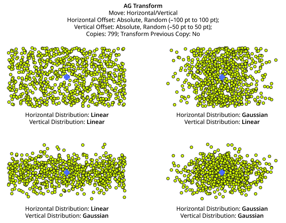
AG Transform Linear Vs. Gaussian Distribution
12. Seed
Each random seed number leads to a different sequence of random values. Clicking the button picks a new seed, thereby changing the look of the artwork. To view or specify the seed number directly, Option/Alt-click the button. This lets you recreate a previously-generated look. The horizontal and vertical components of the offset have independent seeds.
13. Step
Constrains each final offset value (after randomization) to multiples of the specified step value while still remaining in the original range (when possible). For example, if an absolute offset is set to a minimum of 12 pt and a maximum of 24 pt, then normally any value between those amounts might be produced — say, 17.448 pt. But enabling Step with a value of 5 pt would result in only values of 15 pt and 20 pt.
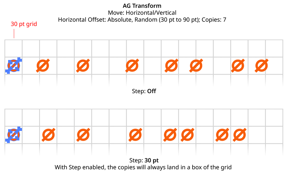
AG Transform Horizontal Offset with Step
When using Step with Relative offsets, two step values are available. The first value is the step value for the relative amount (a percentage), and the second is the step value for the absolute “plus” offset.
Move Section: Distance/Angle
In Distance/Angle mode, the Move section of the dialog has the following controls:
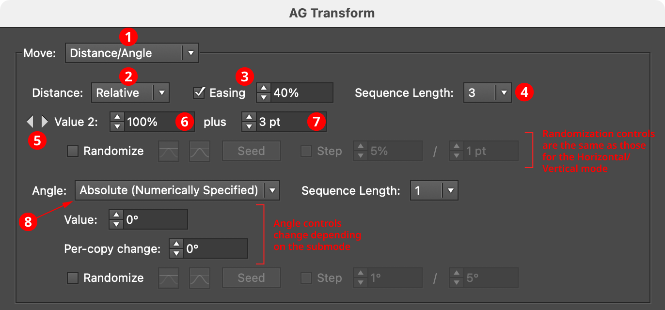
AG Transform Parameters Dialog, Move Section (Distance Angle)
1. Main Mode
The dropdown menu allows the choice between Distance/Angle mode and Horizontal/Vertical mode.
2. Absolute/Relative Submode
The dropdown menu allows the choice between Absolute or Relative submodes for the distance component of the offset. In Absolute submode, the offset is specified using an absolute value, such as 12 pt. In Relative submode, the value is specified using a percentage of the width of its bounding box, plus an additional non-relative value.
3. Distance Easing
Easing controls the final spacing of all of the transformed copies based on their distance from the original object. When enabled, the easing value (from 1% to 99%) specifies where the middle copy should be placed (as a percentage of the distance from the original to the last copy). It therefore determines whether the copies increase their spacing as they get further away from the original (for values less than 50%), or decrease their spacing (for values more than 50%).
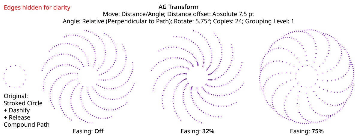
AG Transform Distance Easing
Distance easing can be used with both sequences and randomization.
4. Distance Sequence Length
See Horizontal/Vertical Sequence Length.
5. Previous/Next Value Buttons
Available when the sequence length is set to a value other than 1. Clicking either button will move between the sequence’s values, allowing any of them to be edited.
6. Offset/Minimum Value
The distance value for the current sequence index. In Absolute submode, this is an absolute value like 12 pt. In Relative submode, this is a percentage of the width of the bounding box of the original art. When randomization is enabled, this value specifies the minimum value that may be randomly produced.
7. Maximum Value
Available when randomization is enabled; it specifies the maximum value that may be randomly produced for the current sequence index.
8. Angle Submode
The dropdown menu allows the choice between Absolute (Numerically Specified), Relative (Start Point/End Point), or Relative (Perpendicular to Path) submodes for the angle component of the offset.
Absolute (Numerically Specified) submode: the angle is specified using an absolute value, such as 45°. In this submode, the angle controls are as follows:
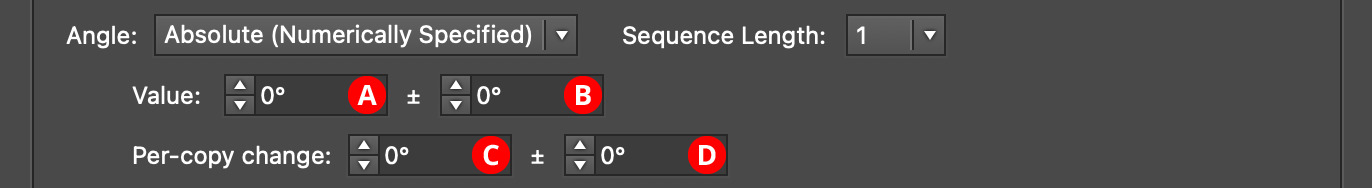
AG Transform Parameters Dialog, Angle Absolute Submode
A. Value/Base Value: The angle component of the offset for the current sequence index. When randomization is enabled, this value specifies the base angle to which a random amount is added or subtracted.
B. Base Value Variation: Available when randomization is enabled; it is the maximum angular amount which is added to or subtracted from the base value to get the random value. For example, if the base value is set to 45°, and the random variation is set to 10°, then angles from 35° to 55° may be produced.
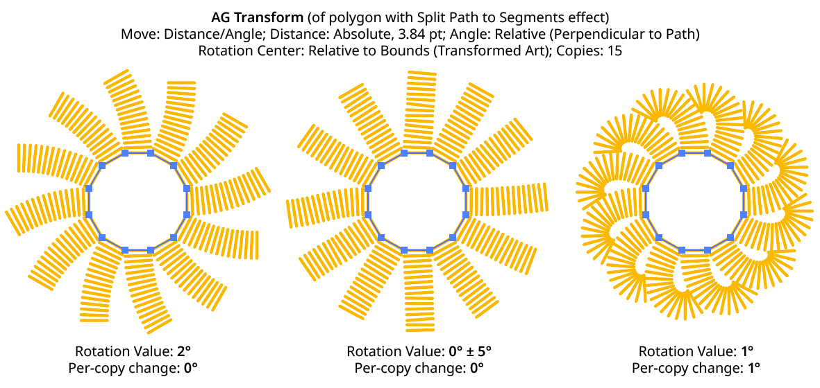
C. Per-copy Change Value: The angular amount to add to the base value for each new copy. For example, if the base value is set to 20°, and the per-copy change is set to 3°, then the first copy will be offset at an angle of 20°, the second at 23°, the third at 26°, and so on. This has the effect of making the copies lie along a circular arc.
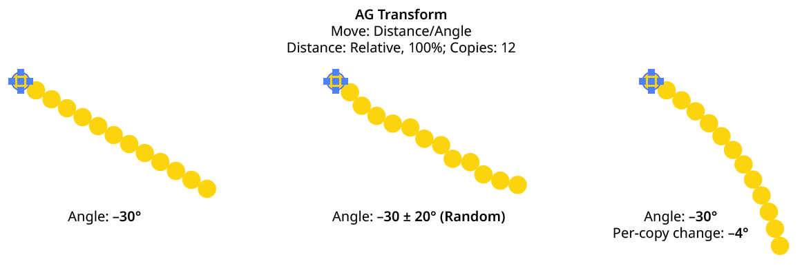
AG Transform Angle Absolute Examples
D. Per-copy Change Value Variation: Available when randomization is enabled; it is the maximum angular amount which is added to or subtracted from the per-copy change value to get the random value.
Relative (Start Point/End Point) submode: the offset angle is that of an imaginary line that starts at one point and ends at another. These points are not necessarily path anchor points, but may be specified using one of five different methods. Relative submodes are most useful when there are multiple objects in the selection that are being transformed. In this submode, the angle controls are as follows:
AG Transform Parameters Dialog, Angle Relative (Start End) Submode
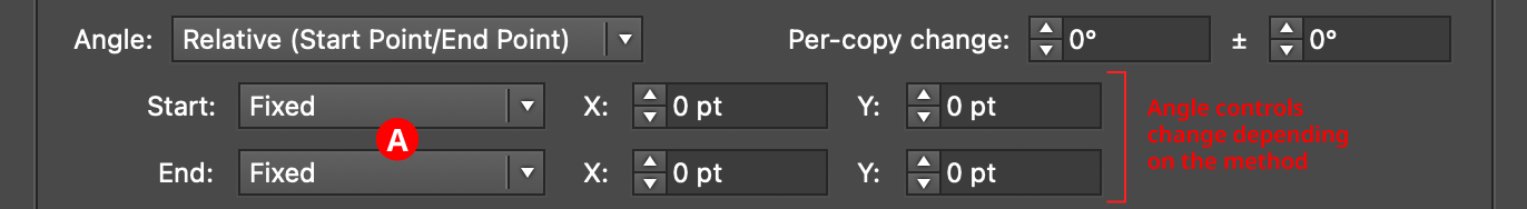
A. Start/End Method: The dropdown menu for both the start and end points allows the choice between five different methods of specifying each point: Fixed, Relative to Bounds, Anchor Point, Position Along Path, or Tagged Path.
Fixed: With this method, the point is simply specified by its coordinates.

AG Transform Start End Point Fixed Controls
There would be no good reason to use Fixed for both the start and end points, because this would only result in the equivalent of an absolute angle. However, if the start point, say, uses Fixed, and the end point uses a different method which specifies the point relative to the art, then the copies will appear to “expand” from a common origin:
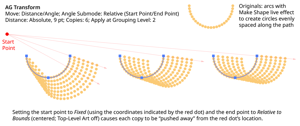
AG Transform Angle Fixed Start End
Relative to Bounds: With this method, the start or end point of the angle-determining line is located relative to the bounds of the original art, using the standard nine-box control. If the Apply at Grouping Level setting is set higher than zero, then the Top-Level Art checkbox becomes available. Turning off Top-Level Art means the bounds of each art object at the specified Grouping Level is used instead, which is usually desirable because each object will, in general, be offset at a different angle.

AG Transform Start End Point Relative to Bounds Controls
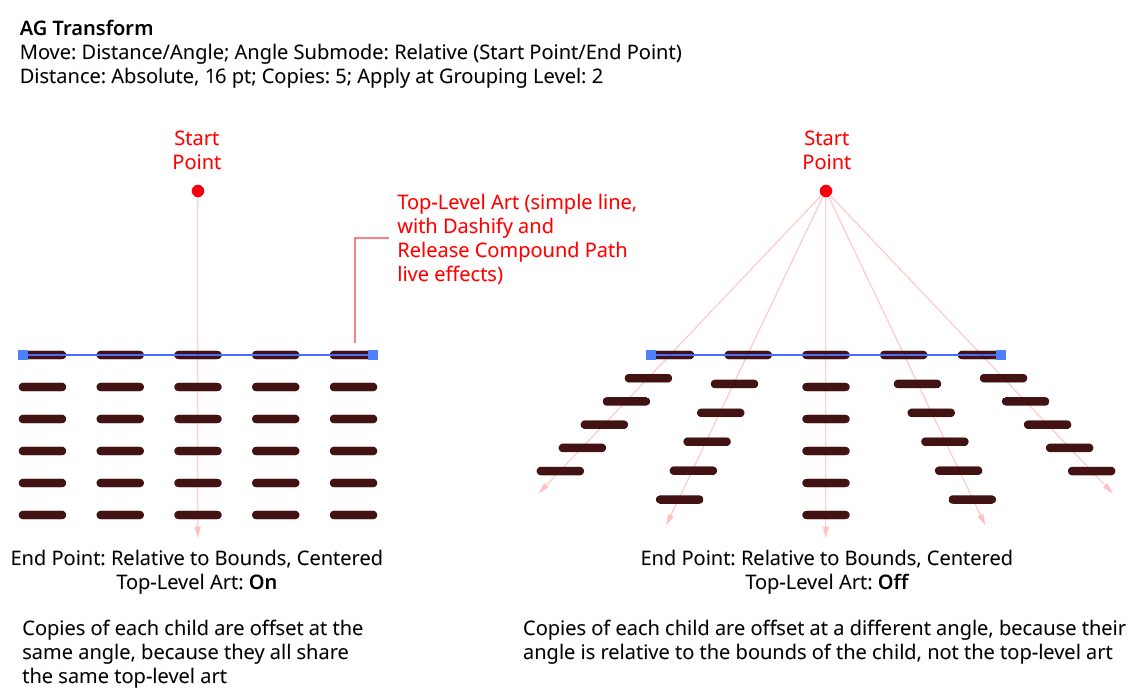
AG Transform Angle Top Level Art
Anchor Point: With this method, the start or end point of the angle-determining line is located at an anchor point of the art object at the current Grouping Level, using the specified index (starting at zero). If the specified index is equal to or greater than the number of points in the path, then the last point on the path is used. If the art object is not a path or does not contain a path, the Relative to Bounds method is used instead.

AG Transform Start End Point Anchor Point Controls
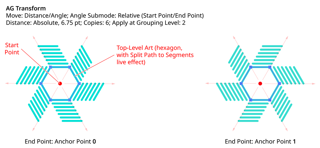
AG Transform Angle Anchor Point
Position Along Path: With this method, the start or end point of the angle-determining line is located at the specified position (from 0% to 100%) along the path of the art object at the current Grouping Level. If the art object is not a path or does not contain a path, the Relative to Bounds method is used instead.

AG Transform Start End Point Position Along Path Controls
Tagged Path: With this method, the start or end point of the angle-determining line is located at the first anchor point of the path contained in the top-level group that has the note “AGTransformStartEndPath” (as entered on the native Attributes panel). It is customary to use a single-point path for this purpose, so the path won’t inadvertently be made visible. If no such path exists, AG Transform uses the first path it finds in the top-level art. If no paths at all exist, the Fixed location is used instead.

AG Transform Start End Point Tagged Path Controls
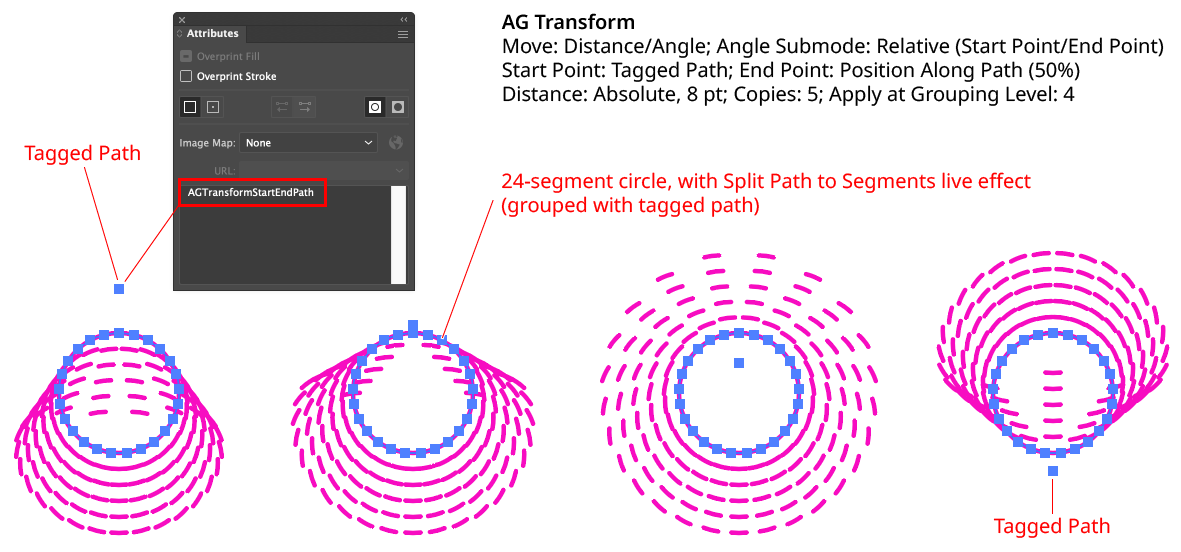
AG Transform Angle Tagged Path
Although similar to Fixed, the Tagged Path method allows the art to be moved around the artboard without changing its appearance, since the Tagged Path moves with it.
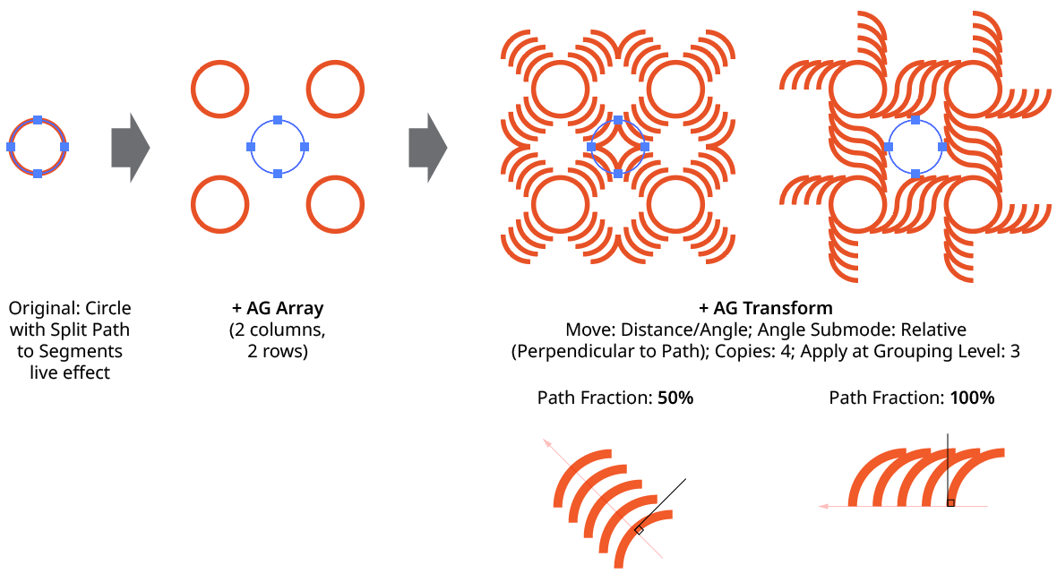
Relative (Perpendicular to Path) submode: the offset angle is perpendicular to the path of the art object at the current Grouping Level (if the art object is not a path or does not contain a path, an angle of 0° is used). The perpendicularity angle is calculated using a “right-hand” rule (i.e., to the right, relative to the direction of the path). Where the perpendicularity is calculated can be specified using either a fraction along the path, or a segment index plus t-value (the bezier-derived distance between the anchor point and the next anchor point). In this submode, the angle controls are as follows:
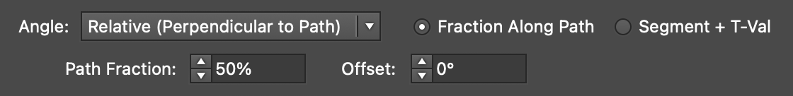
AG Transform Angle Perpendicular Path Fraction Controls
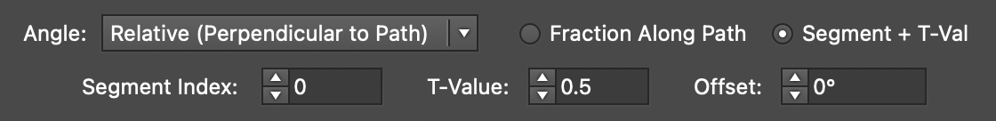
AG Transform Angle Perpendicular Index and T-Val Controls
AG Transform Angle Perpendicular to Path
Using either method (Fraction Along Path or Segment + T-Val), an additional angular offset to the perpendicular angle may be added. Using a value of 180°, for example, can be useful if the path’s direction is the opposite of what is expected.
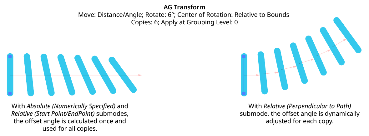
Although the offset angle is calculated once for the Relative (Start Point/End Point) submode and used for all subsequent copies, the angle for the Relative (Perpendicular to Path) submode is dynamically updated with each copy. Thus, if the art is rotated in addition to being offset, the offset angle will change to stay perpendicular to each copy.
AG Transform Angle Perpendicular to Path with Rotation
Rotate Section
The Rotate section of the dialog has the following controls:
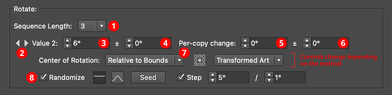
AG Transform Parameters Dialog, Rotate Section
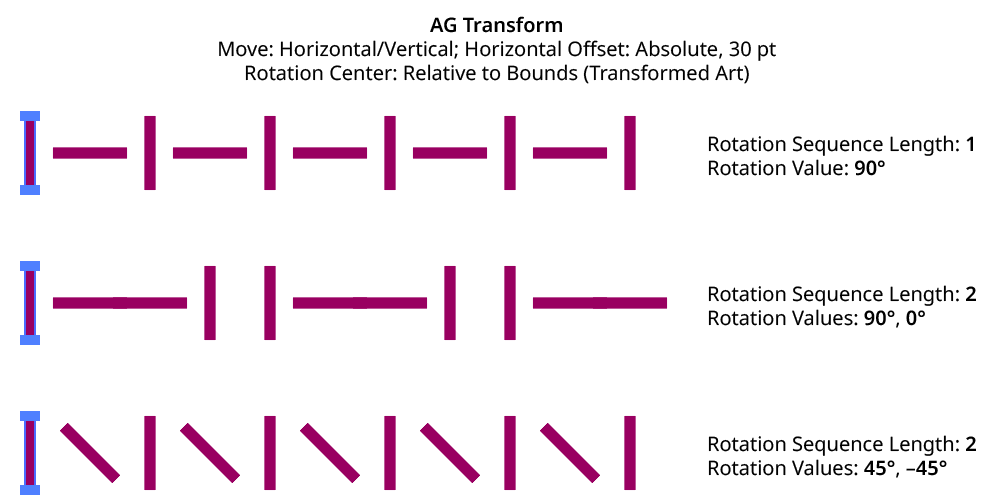
1. Rotation Sequence Length
By default (and ignoring randomization), each copy receives the same rotation value (as with the native Transform effect). However, AG Transform offers sequences, which allow up to 8 different rotation values. If the number of copies exceeds the length of the sequence, the values simply repeat in a cycle. Each member of a sequence shares the same randomization parameters.
AG Transform Rotation Sequence Examples
2. Previous/Next Offset Buttons
Available when the sequence length is set to a value other than 1. Clicking either button will move between the sequence’s values, allowing any of them to be edited.
3. Value/Base Value
The angular value for the current sequence index. When randomization is enabled, this value specifies the base angle to which a random amount is added or subtracted.
4. Base Value Variation
Available when randomization is enabled; it is the maximum angular value which is added to or subtracted from the base value to get the random value. For example, if the base value is set to 45°, and the random variation is set to 10°, then angles from 35° to 55° may be produced.
5. Per-copy Change Value
The angular amount to add to the base value for each new copy. For example, if the base value is set to 20°, and the per-copy change is set to 3°, then the first copy will be rotated 20°, the second at 23°, the third at 26°, and so on.
6. Per-copy Change Value Variation
Available when randomization is enabled; it is the maximum angular amount which is added to or subtracted from the per-copy change value to get the random value.
AG Transform Rotation Examples
7. Center of Rotation
The dropdown menu allows the choice between six different methods of specifying the center of rotation: Fixed, Relative to Bounds, Anchor Point, Position Along Path, Tagged Path, or Along Line.
Fixed: With this method, the center of rotation is simply specified by its coordinates.

AG Transform Center of Rotation Fixed Controls
This could be used to make multiple objects rotate around a common center, even if their position is subsequently adjusted:
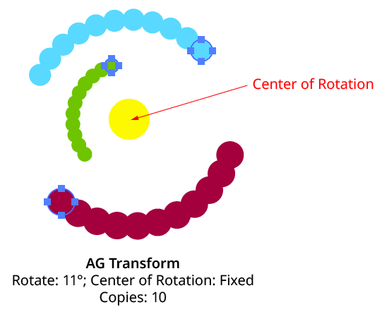
AG Transform Rotate Center Fixed
Relative to Bounds: This method (when used with Top-Level Art) is what the native Transform effect uses.

AG Transform Center of Rotation Relative to Bounds Controls
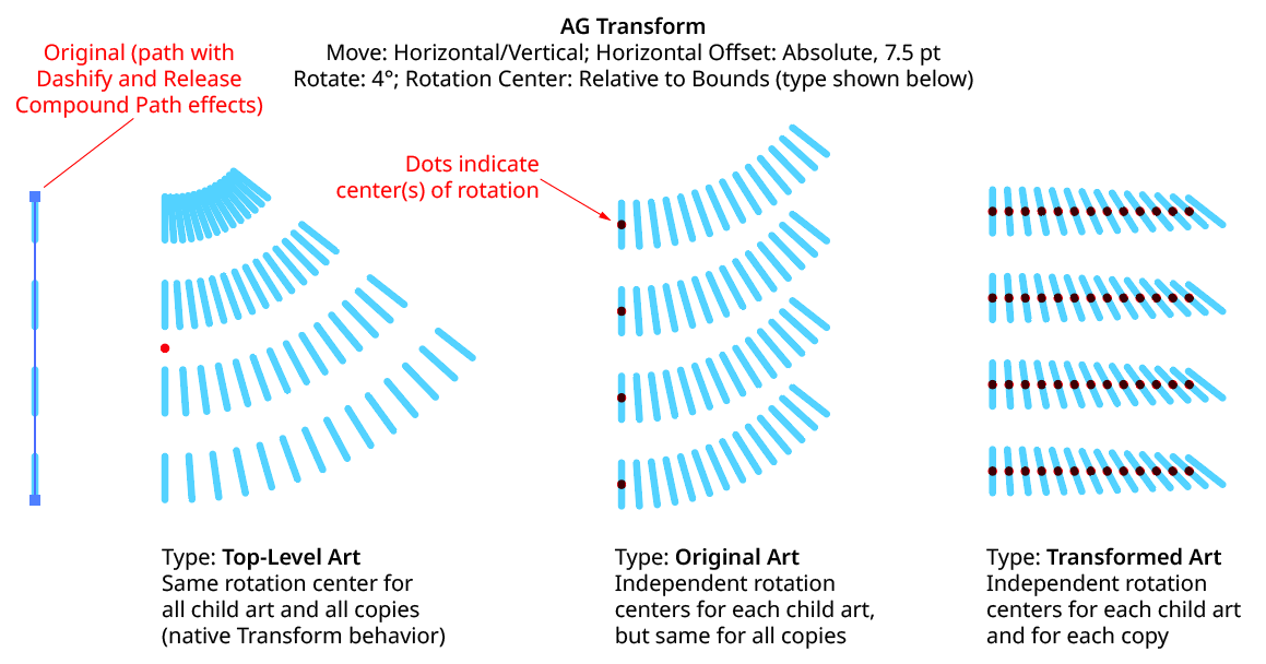
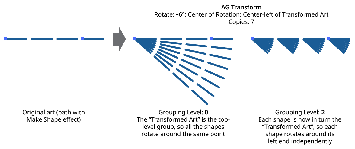
With this method, the center of rotation is located relative to the bounds of the specified art, using the standard nine-box control. The choices for the art type are Top-Level Art, Original Art, or Transformed Art. Top-Level Art is the art to which the AG Transform effect was applied (which may be a group). Original Art is the art at the specified Grouping Level which is being independently transformed, using its initial position for all copies. Transformed Art also refers to this art, but uses the transformed bounds for each copy, i.e., the center of rotation moves along with the copies.
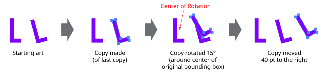
To understand how changing the rotation center’s art type affects the results, it is helpful to understand the order of transform operations. For example, applying a native Transform effect with both a horizontal move and a rotation results in the left-hand image below and not the right-hand one — but why?
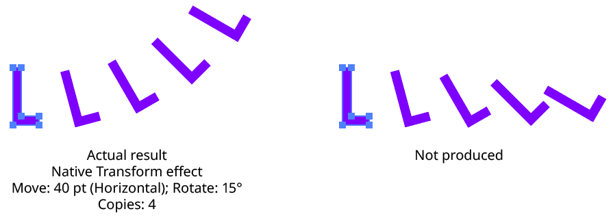
Native Transform Move Plus Rotate Example
The answer is due to two factors: the order of the transform operations, and the method of locating the center of rotation for each copy. For both the native Transform effect and AG Transform, each copy of the art is first scaled, then rotated, and finally moved (offset). The native Transform effect locates the center of rotation using the bounding box of the original art, and that center is used for all subsequent copies. Thus, the transform could be manually created as follows: Starting with the original art, a copy is made in place which is then rotated 15° around the center of rotation (the bounding box center). Then it is offset 40 pt to the right.
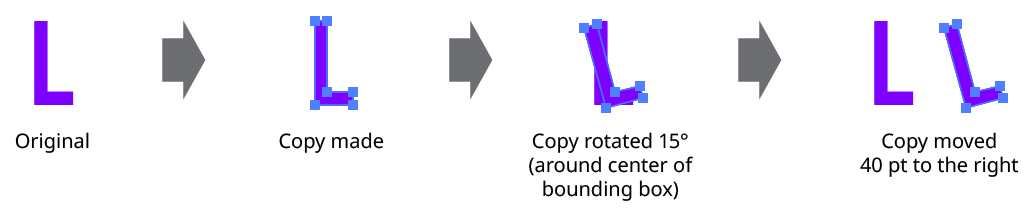
Native Transform Move Plus Rotate Manual Creation
This process is repeated for the second copy. Importantly, the center of rotation remains located at the center of the bounding box of the original art.
Native Transform Move Plus Rotate Manual Creation with Multiple Copies
The same steps are followed for each subsequent copy, which leads to the results shown originally.
AG Transform can be made to act like the native Transform effect for rotation by setting the Center of Rotation method to Relative to Bounds and the art type to Top-Level Art. However, the other two art types offer additional options:
AG Transform Rotate Center Relative to Bounds Examples
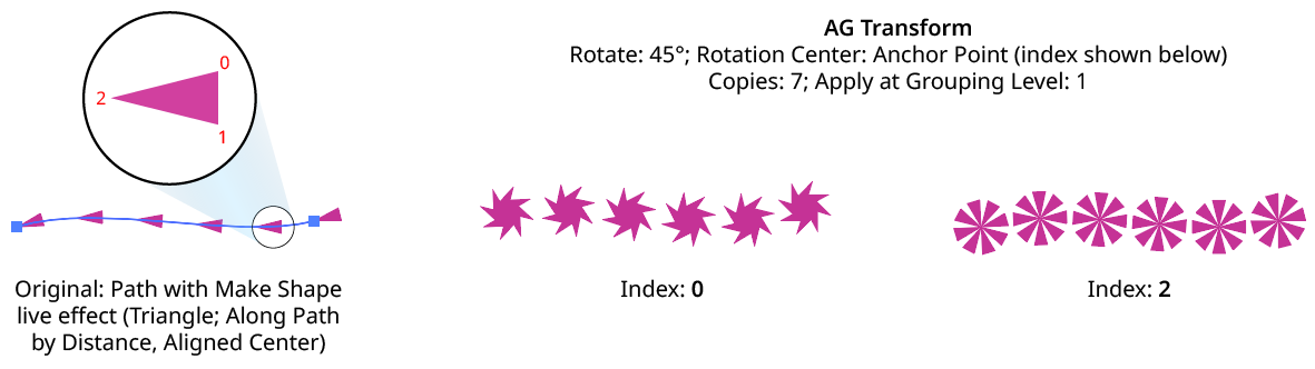
Anchor Point: With this method, the center of rotation is located at the specified anchor point of the art at the specified grouping level. The rotation point is transformed for each copy, along with the art. If the art does not contain a path, the Relative to Bounds method will be used instead.

AG Transform Center of Rotation Anchor Point Controls
AG Transform Rotate Center Anchor Point Examples
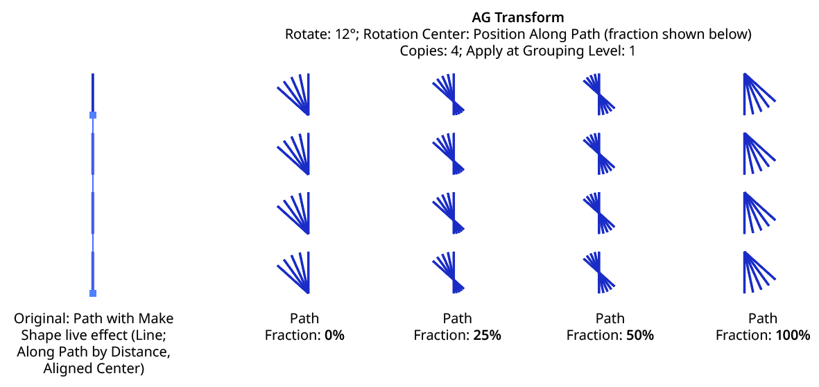
Position Along Path: With this method, the center of rotation is located along the path of the art (from 0% to 100%) at the specified grouping level. The rotation point is transformed for each copy, along with the art. If the art does not contain a path, the Relative to Bounds method will be used instead.

AG Transform Center of Rotation Position Along Path Controls
AG Transform Rotate Center Position Along Path Examples
Tagged Path: With this method, the center of rotation is located at the first anchor point of a path contained in the top-level group that has the note “AGTransformRotatePath” (as entered on the native Attributes panel). It is customary to use a single-point path for this purpose, so the path won’t inadvertently be made visible. If no such path exists, AG Transform uses the first path it finds in the top-level art. If no paths at all exist, the Relative to Bounds method will be used instead.

AG Transform Center of Rotation Tagged Path Controls
Along Line: With this method, the center of rotation is located along an imaginary line that passes through two points which are located using anchor point indices and t-values in the path art at the specified grouping level. The rotation point is transformed for each copy, along with the art. If the art does not contain a path, the Relative to Bounds method will be used instead.

AG Transform Rotate Center Along Line Controls
A. Start Index: The index of the anchor point used to locate the start of the imaginary line.
B. Start T-Val: The t-value (bezier-derived distance between the anchor point and the next anchor point, ranging from 0 to 1) of the start point.
C. End Index: The index of the anchor point used to locate the end of the imaginary line.
D. End T-Val: The t-value (bezier-derived distance between the anchor point and the next anchor point, ranging from 0 to 1) of the end point.
E. Fraction: The position of the center of rotation, as a fraction of the distance between the start point of the imaginary line and the end point. Values between 0% and 100% would put this point between the start and end, but the value can also be negative or greater than 100% to put the point outside this interval.
The Along Line method is similar to the Relative to Bounds method in that the center of rotation is always relative to the artwork. However, while Relative to Bounds only offers nine distinct positions, Along Line can specify an infinite number of such positions.
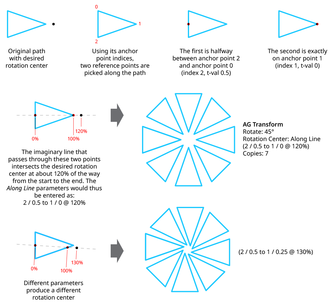
AG Transform Rotate Center Along Line Examples
8. Randomize
Randomization works the same way in the Rotate section of the dialog as it does in the Angle area of the Move section (when in Distance/Angle mode). Step values can be set for both the regular rotation value and for the per-copy change value.
Scale Section
The Scale section of the dialog has the following controls:
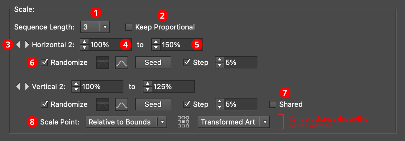
AG Transform Parameters Dialog - Scale Section
1. Rotation Sequence Length
By default (and ignoring randomization), each copy receives the same scaling value (as with the native Transform effect). However, AG Transform offers sequences, which allow up to 8 different scaling values. If the number of copies exceeds the length of the sequence, the values simply repeat in a cycle. Each member of a sequence shares the same randomization parameters.
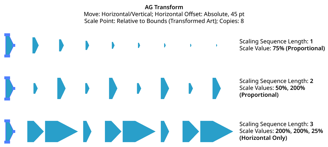
AG Transform Scaling Sequence Examples
2. Keep Proportional
When enabled, scaling will always be proportional (the vertical scaling values will be automatically set to match the horizontal scaling values).
3. Previous/Next Offset Buttons
Available when the sequence length is set to a value other than 1. Clicking either button will move between the sequence’s values, allowing any of them to be edited.
4. Value/Minimum Value
The horizontal (or vertical) scaling value for the current sequence index, from –10000% to 10000%. Negative values have the effect of flipping the object across the corresponding axis (the same as using the Reflect X or Reflect Y checkboxes in the native Transform dialog). When randomization is enabled, this value specifies the minimum value that may be randomly produced.
5. Maximum Value
Available when randomization is enabled; it specifies the maximum horizontal (or vertical) scaling value that may be randomly produced for the current sequence index.
6. Randomize
Randomization works the same way in the Scale section of the dialog as it does in the Move section. Both horizontal and vertical scaling can have independent randomization parameters.
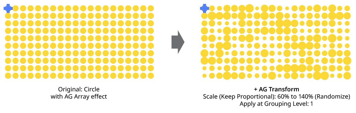
AG Transform Random Scale
7. Shared
When enabled, the random number for each copy (i.e., its random position between the specified minimum and maximum) will be the same for the vertical scaling as the horizontal scaling, allowing the transformed aspect ratio of each copy to be maintained.
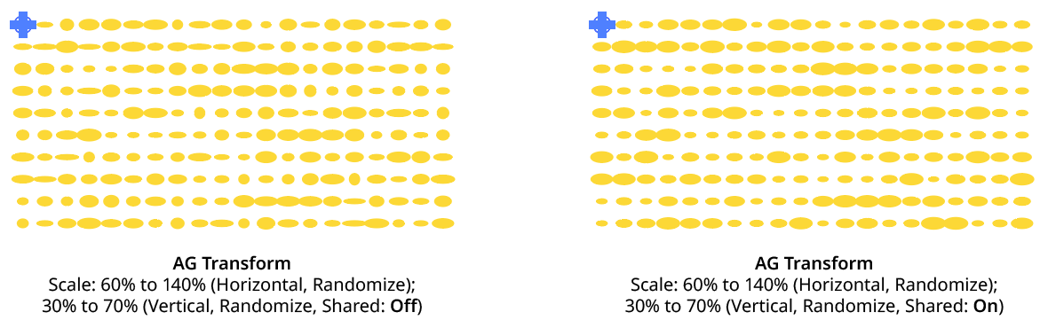
AG Transform Random Scale (Non-Shared Vs. Shared)
8. Scale Point
Just as with specifying the Center of Rotation, the dropdown menu allows the choice between six different methods of specifying the point through which the art is scaled: Fixed, Relative to Bounds, Anchor Point, Position Along Path, Tagged Path, or Along Line. See Center of Rotation in the Rotate section for an explanation of the methods.
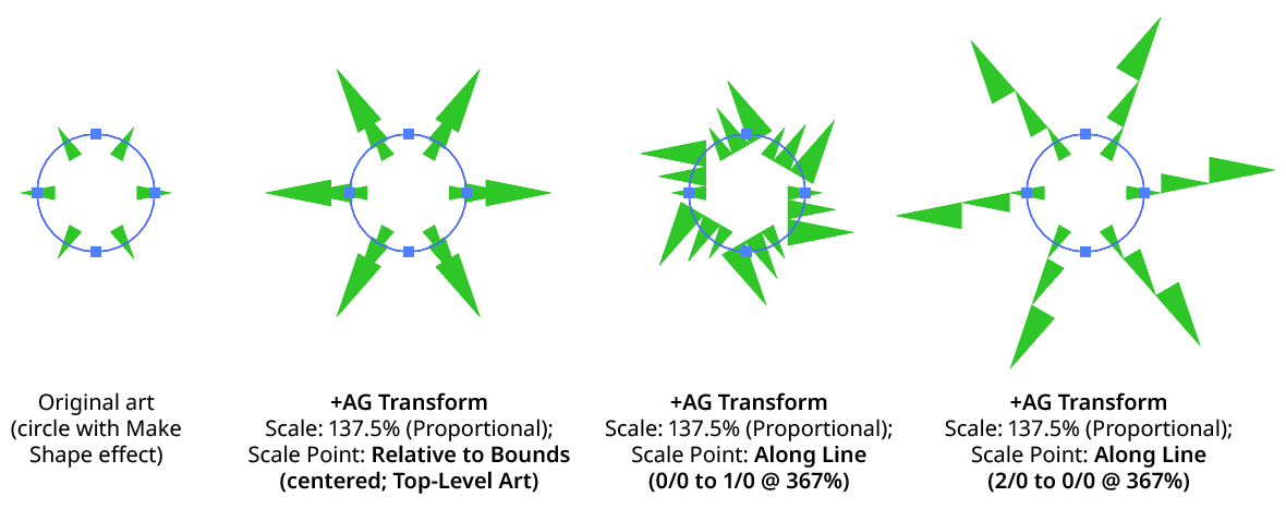
AG Transform Scale Point Examples
Bottom Section
The Bottom section of the dialog has the following controls:
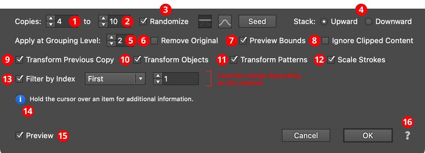
AG Transform Parameters Dialog - Bottom Section
1. Copies
The number of copies to make for each art object at the specified grouping level. This is the same as the setting in the native Transform effect. When copy randomization is enabled, this value represents the minimum number of copies that may be randomly produced.
2. Maximum Copies
Available when copy randomization is enabled; it specifies the maximum number of copies that may be randomly produced.
3. Copies Randomize
When randomization is enabled, the number of copies is not fixed for each object, but is chosen randomly between the specified minimum and maximum values. The distribution of those values (linearly or in a Gaussian manner) can be specified, as well as the random seed.
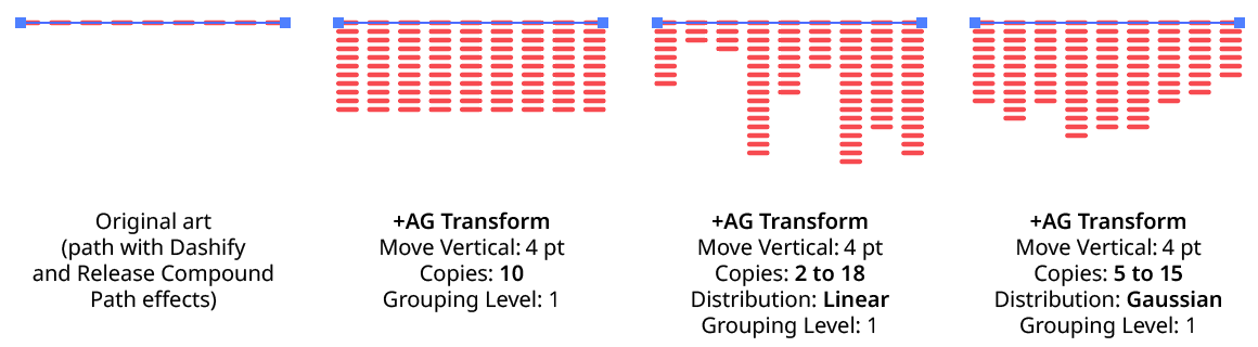
AG Transform Copy Randomization Examples
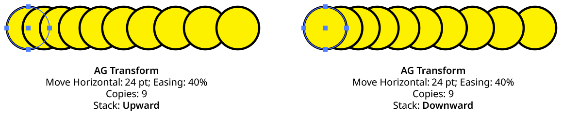
4. Stack
Specifies whether each copy is created upward or downward in the stacking order (the native Transform effect always stacks downward).
AG Transform Stacking Order
5. Apply at Grouping Level
Unless a live effect is applied above all strokes and fills (a “pre” effect), or inside a stroke or a fill and above other live effects, the art object internally passed to it is always a group. And this group may contain other groups, and so on. The Grouping Level controls the level at which the effect is applied, which affects what elements in the hierarchy get different random transformations as well as how the center of rotation and scale point are calculated. The Grouping Level can range from 0 (representing the top-level art) to 29 (the deepest level of group nesting allowed in Illustrator).
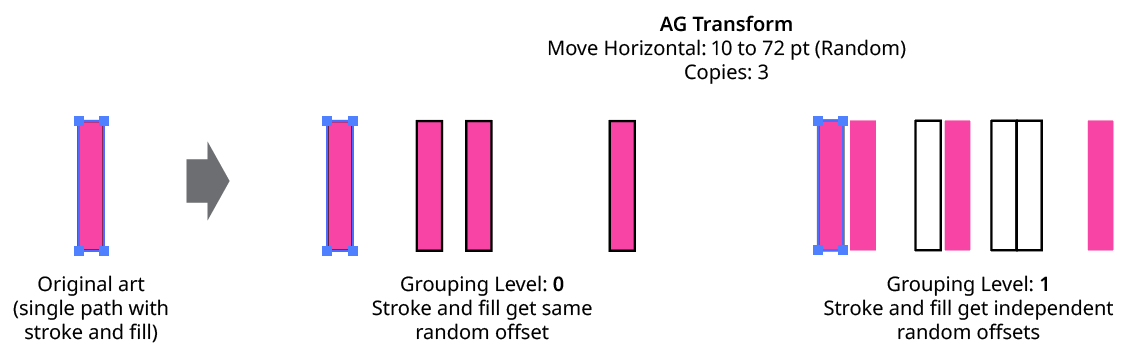
In the simplest case (when AG Transform is applied to a single stroked-and-filled path), the live effect mechanism separates the stroke from the fill, and passes a stroke-only path and a fill-only path to the live effect in a group. So while a Grouping Level of 0 would apply the same transformation to the stroke and fill (because it is applied to the top-level group), a Grouping Level of 1 would cause it to consider the stroke and fill as separate objects, and if randomization was on, they would get different random values:
AG Transform Grouping Level on Simple Path
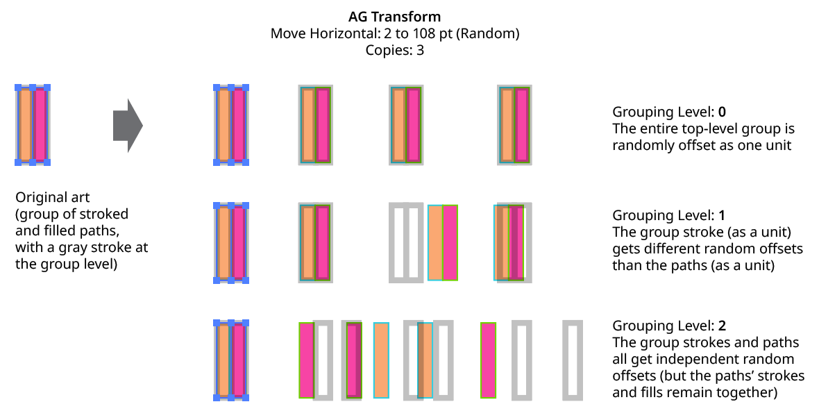
Next, consider the case of applying AG Transform to a group of stroked and filled paths. This top-level group may or may not have its own stroke and/or fill in its appearance. Here, the group passed to the effect has three groups inside it. One is composed of the paths with group level strokes (if there is no group level stroke, these would have no stroke or fill); another is composed of the paths with group level fills (similarly, if there is no group level fill, these would also have no stroke or fill); and the last is composed of the original paths in the group (and here, strokes and fills are not broken apart).
AG Transform Grouping Level on Group of Paths
In general, each nested group in the original art requires two Grouping Levels to “dig into,” due to the fact that a group stroke or fill can be present at each level. Because it can be difficult to anticipate what Grouping Level to use because the live effect mechanism can be complicated, it is recommended to simply increase the Grouping Level until the results are what is desired (modifying the seed or seeds, if necessary, to see what is really changing independently). Setting the Grouping Level above the highest “valid” value will not cause a problem.
AG Transform Grouping Level and Rotation Center
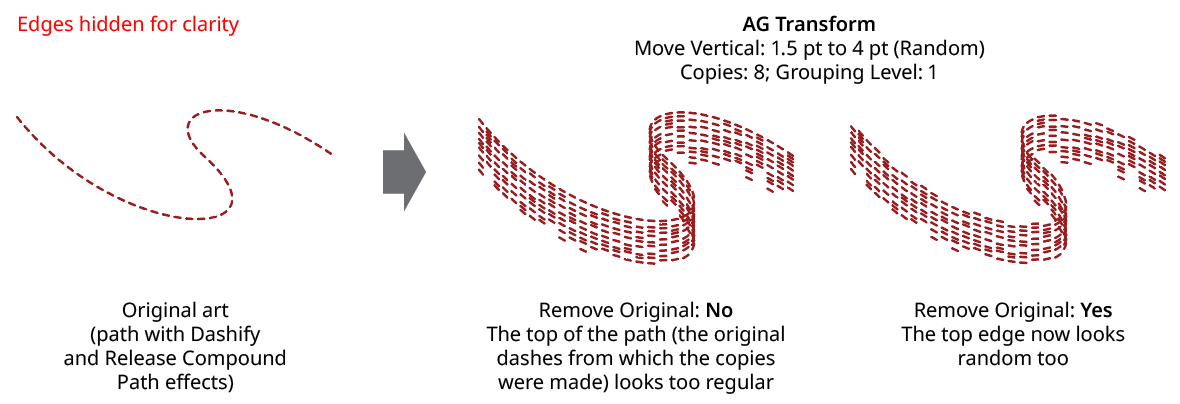
6. Remove Original
Available if the number of copies is greater than zero. When enabled, the original art to which the effect was applied will be suppressed in its final appearance. This is often useful when using random transformations but the original is regular and spoils the random look.
AG Transform Remove Original
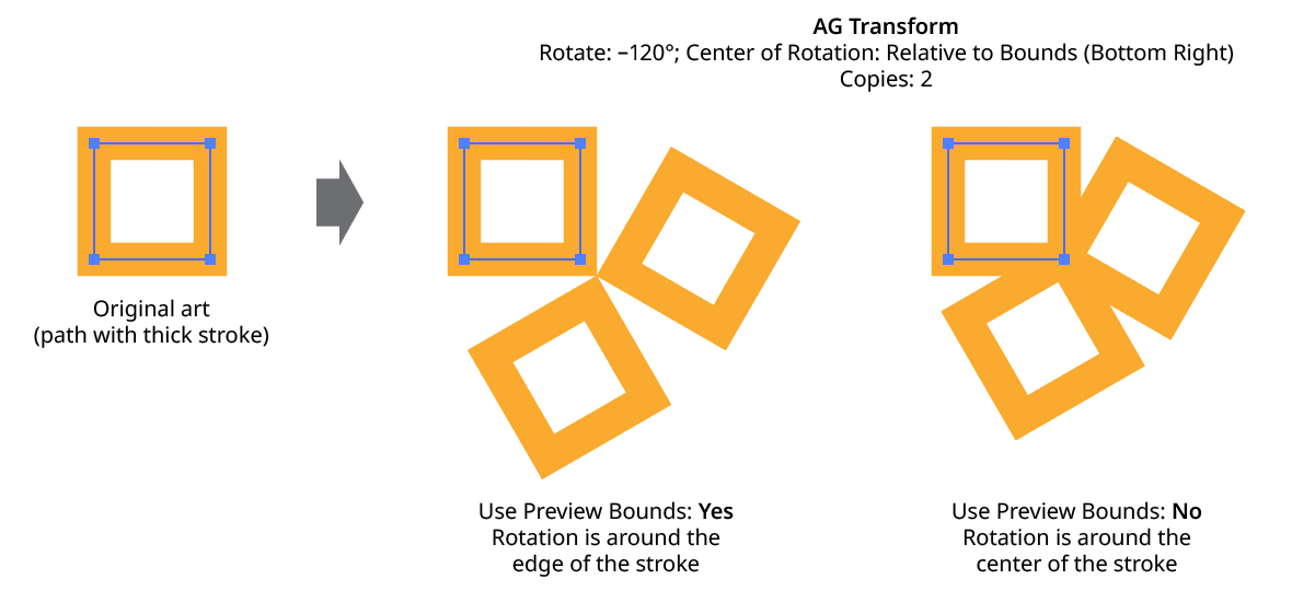
7. Use Preview Bounds
Overrides the general preference of the same name. When enabled, the strokes of the artwork are included in its bounding box, which affects the position of the Center of Rotation or Scale Point when they are set to Relative to Bounds:
AG Transform Use Preview Bounds
8. Ignore Clipped Content
When enabled, and the art is a clip group, then only the clipping path is used for the purposes of bounds determination. This affects, for instance, the Move offsets when in Relative mode, or the position of the Center of Rotation or Scale Point when they are set to Relative to Bounds.
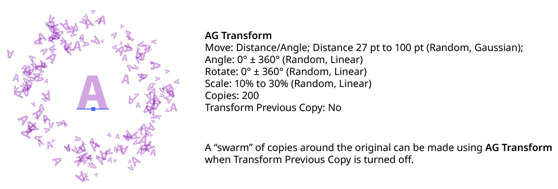
9. Transform Previous Copy
By default (and as with the native Transform effect), each copy after the first is created by transforming the previous copy. However, when using randomization, it can sometimes be useful to always start with the original art’s position and transform it to create each copy:
AG Transform Transform Previous Copy
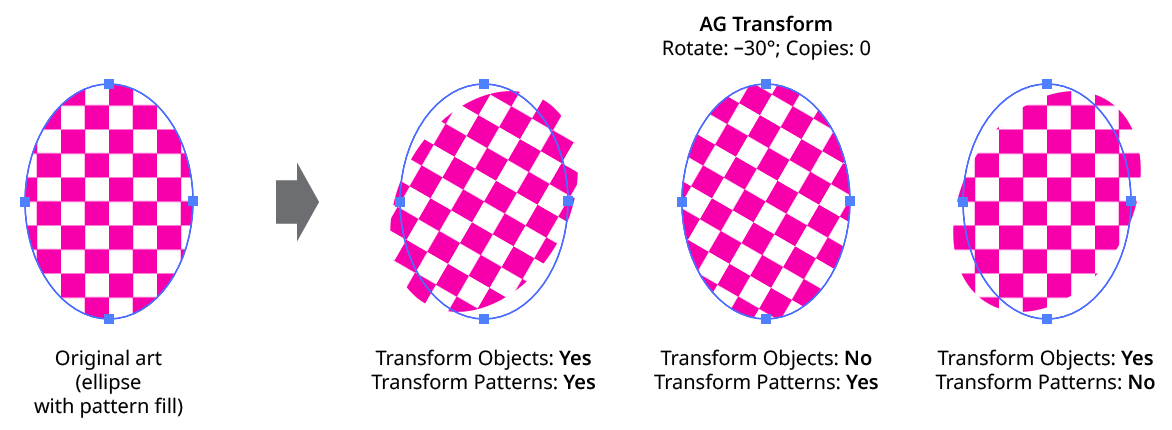
10. Transform Objects
This option works the same as that for the native Transform effect. When disabled, only the pattern(s) contained in the art are transformed.
11. Transform Patterns
This option works the same as that for the native Transform effect. When disabled, pattern(s) contained in the art are not transformed along with the art.
AG Transform Objects and Patterns
12. Scale Strokes
When disabled, and the AG Transform contains scaling, strokes within the artwork will retain their original weight.
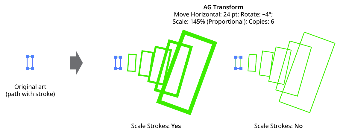
AG Transform Scale Strokes
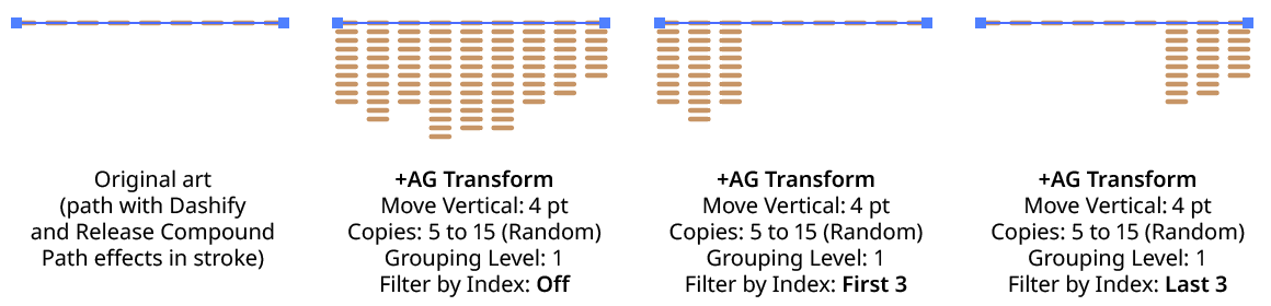
13. Filter By Index
When enabled, each art object’s index is used to determine whether it should be transformed, using one of seven different methods. The index is simply an integer sequentially assigned to each object at the specified Grouping Level in the order it is encountered, starting with zero for the first object. Generally, the index increases going downwards in the stacking order; however, other live effects present in the appearance stack may change this order, sometimes randomly (such as PathFinder effects). Additionally, objects may be created which are invisible in the final appearance if they have no fill or stroke. The available By Index methods are as follows:
a. First: Only the first n objects are affected, where n is the specified value.

AG Transform Filter by Index - First Controls
b. Last: Only the last n objects are affected, where n is the specified value.

AG Transform Filter by Index - Last Controls
AG Transform Filter by Index - First, Last
c. First or Last: Only the first and last objects are affected.
d. Odd: Only objects with an odd index (1, 3, 5, 7...) are affected.
e. Even: Only objects with an even index (0, 2, 4, 6...) are affected.
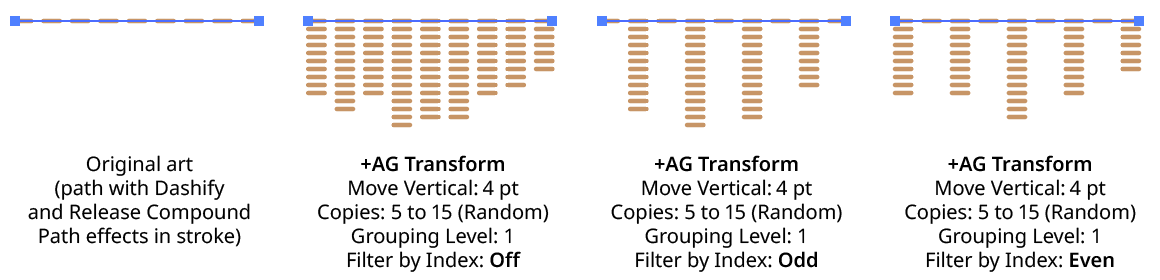
AG Transform Filter by Index - Odd, Even
f. Pattern: Creates a repeating pattern of matching indices based on the three pattern parameters.

AG Transform Filter by Index - Pattern Controls
Initial Skip specifies the number of indices to skip over at the start (art with these indices will not be affected). Then, Match specified the number of indices that will match and therefore be affected. Finally, Skip specifies the number of indices to skip over following the matching indices. When the total of the values in the three parameters is less than the number of eligible art objects, the pattern repeats, using the Match and Skip values in alternation.
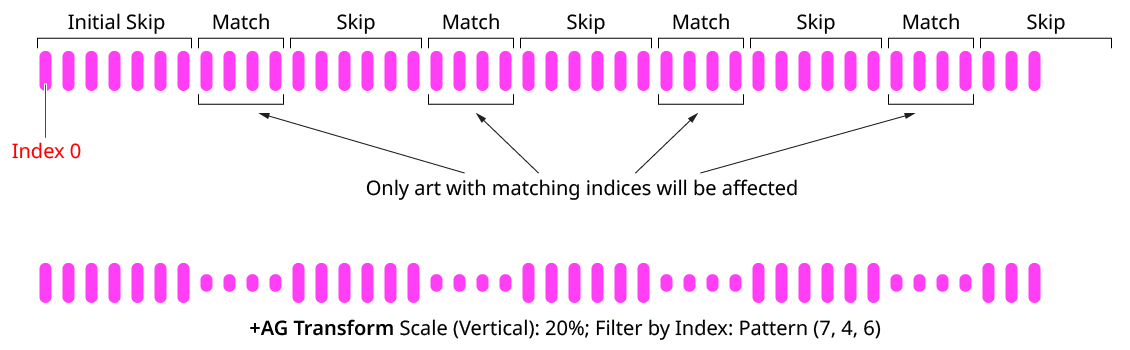
AG Transform Filter by Index - Pattern
g. Randomly: Each art object has the specified random chance (from 0% to 100%) of being affected. The parameter has an independent seed value. Just as with move/rotate/scale seed values, clicking the button picks a new seed, thereby changing the look of the artwork. To view or specify the seed number directly,
Option/Alt-clickthe button. This lets you recreate a previously-generated look.

AG Transform Filter by Index - Randomly Controls

AG Transform Filter by Index - Randomly
14. Informational area
Shows a brief description of each control when the cursor is being hovered over it.
15. Preview
As with all live effects, when enabled, changing a parameter will immediately update the artwork while the dialog is still open.
16. Help Button
Opens the help documentation in the Astute Manager. If this does not automatically appear, please ensure your Astute Manager is running first.