 Move Section: Distance/Angle
In Distance/Angle mode, the Move section of the dialog has the following controls:
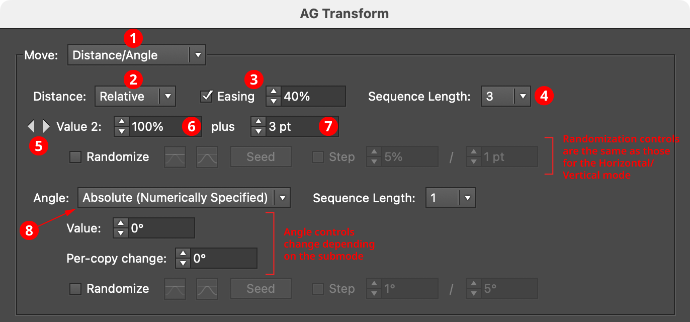
AG Transform Parameters Dialog, Move Section (Distance Angle)
1. Main Mode
The dropdown menu allows the choice between Distance/Angle mode and Horizontal/Vertical mode.
2. Absolute/Relative Submode
The dropdown menu allows the choice between Absolute or Relative submodes for the distance component of the offset. In Absolute submode, the offset is specified using an absolute value, such as 12 pt. In Relative submode, the value is specified using a percentage of the width of its bounding box, plus an additional non-relative value.
3. Distance Easing
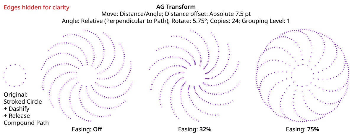
Easing controls the final spacing of all of the transformed copies based on their distance from the original object. When enabled, the easing value (from 1% to 99%) specifies where the middle copy should be placed (as a percentage of the distance from the original to the last copy). It therefore determines whether the copies increase their spacing as they get further away from the original (for values less than 50%), or decrease their spacing (for values more than 50%).
AG Transform Distance Easing
Distance easing can be used with both sequences and randomization.
4. Distance Sequence Length
See Horizontal/Vertical Sequence Length.
5. Previous/Next Value Buttons
Available when the sequence length is set to a value other than 1. Clicking either button will move between the sequence’s values, allowing any of them to be edited.
6. Offset/Minimum Value
The distance value for the current sequence index. In Absolute submode, this is an absolute value like 12 pt. In Relative submode, this is a percentage of the width of the bounding box of the original art. When randomization is enabled, this value specifies the minimum value that may be randomly produced.
7. Maximum Value
Available when randomization is enabled; it specifies the maximum value that may be randomly produced for the current sequence index.
8. Angle Submode
The dropdown menu allows the choice between Absolute (Numerically Specified), Relative (Start Point/End Point), or Relative (Perpendicular to Path) submodes for the angle component of the offset.
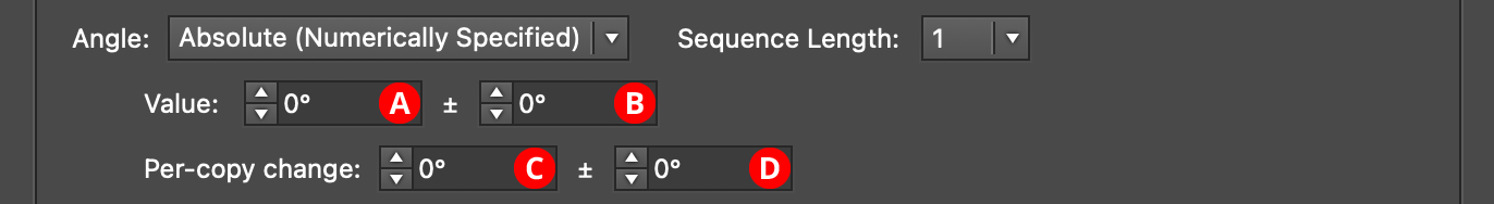
Absolute (Numerically Specified) submode: the angle is specified using an absolute value, such as 45°. In this submode, the angle controls are as follows:
AG Transform Parameters Dialog, Angle Absolute Submode
A. Value/Base Value: The angle component of the offset for the current sequence index. When randomization is enabled, this value specifies the base angle to which a random amount is added or subtracted.
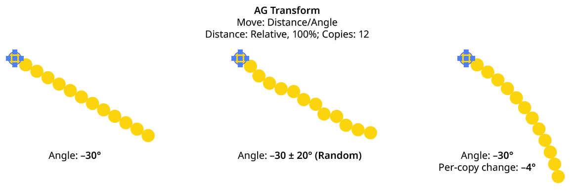
B. Base Value Variation: Available when randomization is enabled; it is the maximum angular amount which is added to or subtracted from the base value to get the random value. For example, if the base value is set to 45°, and the random variation is set to 10°, then angles from 35° to 55° may be produced.
C. Per-copy Change Value: The angular amount to add to the base value for each new copy. For example, if the base value is set to 20°, and the per-copy change is set to 3°, then the first copy will be offset at an angle of 20°, the second at 23°, the third at 26°, and so on. This has the effect of making the copies lie along a circular arc.
AG Transform Angle Absolute Examples
D. Per-copy Change Value Variation: Available when randomization is enabled; it is the maximum angular amount which is added to or subtracted from the per-copy change value to get the random value.
Relative (Start Point/End Point) submode: the offset angle is that of an imaginary line that starts at one point and ends at another. These points are not necessarily path anchor points, but may be specified using one of five different methods. Relative submodes are most useful when there are multiple objects in the selection that are being transformed. In this submode, the angle controls are as follows:
AG Transform Parameters Dialog, Angle Relative (Start End) Submode
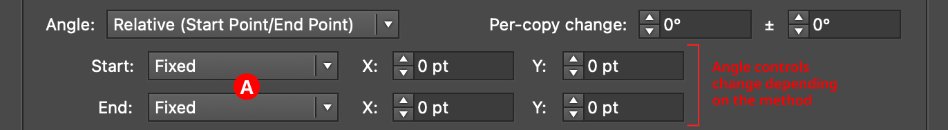
A. Start/End Method: The dropdown menu for both the start and end points allows the choice between five different methods of specifying each point: Fixed, Relative to Bounds, Anchor Point, Position Along Path, or Tagged Path.
Fixed: With this method, the point is simply specified by its coordinates.

AG Transform Start End Point Fixed Controls
There would be no good reason to use Fixed for both the start and end points, because this would only result in the equivalent of an absolute angle. However, if the start point, say, uses Fixed, and the end point uses a different method which specifies the point relative to the art, then the copies will appear to “expand” from a common origin:
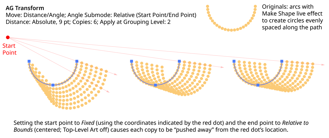
AG Transform Angle Fixed Start End
Relative to Bounds: With this method, the start or end point of the angle-determining line is located relative to the bounds of the original art, using the standard nine-box control. If the Apply at Grouping Level setting is set higher than zero, then the Top-Level Art checkbox becomes available. Turning off Top-Level Art means the bounds of each art object at the specified Grouping Level is used instead, which is usually desirable because each object will, in general, be offset at a different angle.

AG Transform Start End Point Relative to Bounds Controls
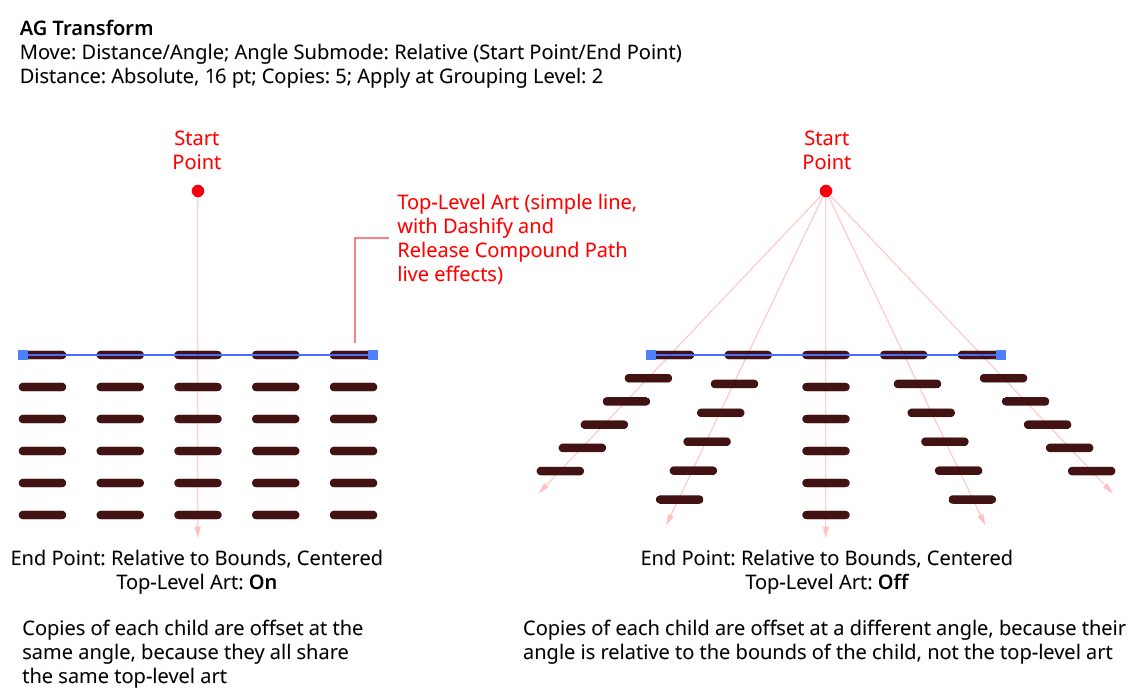
AG Transform Angle Top Level Art
Anchor Point: With this method, the start or end point of the angle-determining line is located at an anchor point of the art object at the current Grouping Level, using the specified index (starting at zero). If the specified index is equal to or greater than the number of points in the path, then the last point on the path is used. If the art object is not a path or does not contain a path, the Relative to Bounds method is used instead.

AG Transform Start End Point Anchor Point Controls
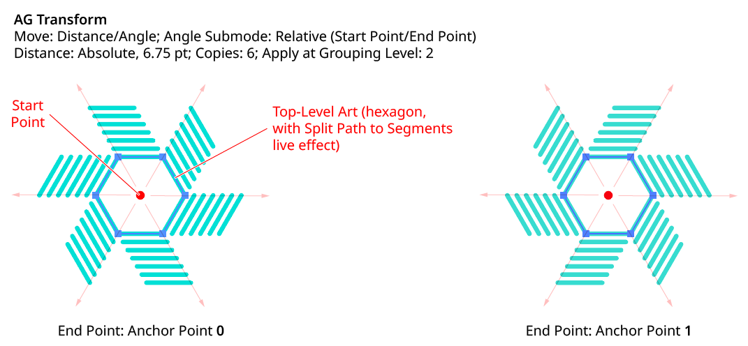
AG Transform Angle Anchor Point
Position Along Path: With this method, the start or end point of the angle-determining line is located at the specified position (from 0% to 100%) along the path of the art object at the current Grouping Level. If the art object is not a path or does not contain a path, the Relative to Bounds method is used instead.

AG Transform Start End Point Position Along Path Controls
Tagged Path: With this method, the start or end point of the angle-determining line is located at the first anchor point of the path contained in the top-level group that has the note “AGTransformStartEndPath” (as entered on the native Attributes panel). It is customary to use a single-point path for this purpose, so the path won’t inadvertently be made visible. If no such path exists, AG Transform uses the first path it finds in the top-level art. If no paths at all exist, the Fixed location is used instead.

AG Transform Start End Point Tagged Path Controls
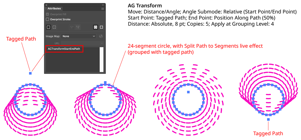
AG Transform Angle Tagged Path
Although similar to Fixed, the Tagged Path method allows the art to be moved around the artboard without changing its appearance, since the Tagged Path moves with it.
Relative (Perpendicular to Path) submode: the offset angle is perpendicular to the path of the art object at the current Grouping Level (if the art object is not a path or does not contain a path, an angle of 0° is used). The perpendicularity angle is calculated using a “right-hand” rule (i.e., to the right, relative to the direction of the path). Where the perpendicularity is calculated can be specified using either a fraction along the path, or a segment index plus t-value (the bezier-derived distance between the anchor point and the next anchor point). In this submode, the angle controls are as follows:
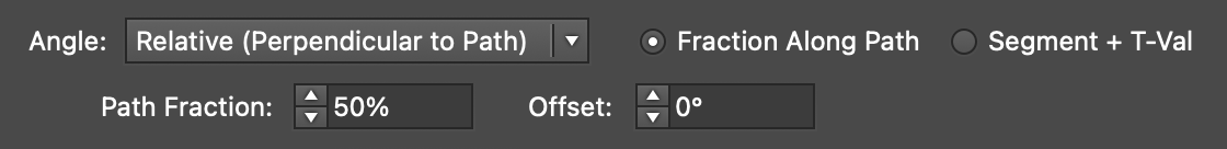
AG Transform Angle Perpendicular Path Fraction Controls
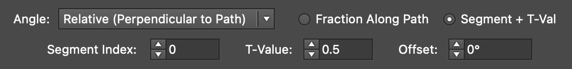
AG Transform Angle Perpendicular Index and T-Val Controls
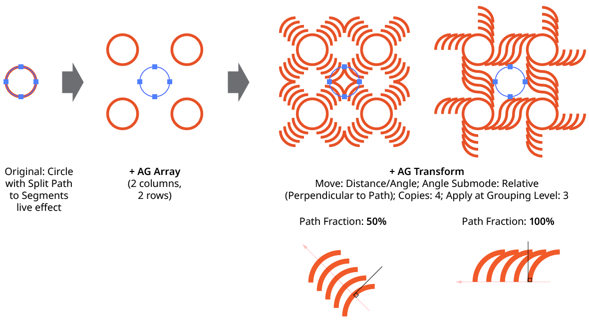
AG Transform Angle Perpendicular to Path
Using either method (Fraction Along Path or Segment + T-Val), an additional angular offset to the perpendicular angle may be added. Using a value of 180°, for example, can be useful if the path’s direction is the opposite of what is expected.
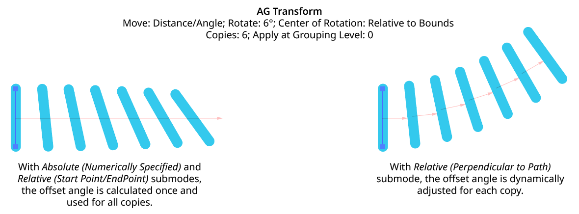
Although the offset angle is calculated once for the Relative (Start Point/End Point) submode and used for all subsequent copies, the angle for the Relative (Perpendicular to Path) submode is dynamically updated with each copy. Thus, if the art is rotated in addition to being offset, the offset angle will change to stay perpendicular to each copy.
AG Transform Angle Perpendicular to Path with Rotation